1
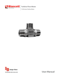
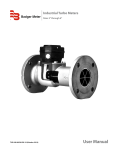
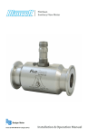
Turbine Flow Meter
B1500 Series
Shown with Blancett B3000
TRB-UM-01798-EN-01 (October 2015)
User Manual
Turbine Flow Meter, B1500 Series
Page ii
TRB-UM-01798-EN-01
October 2015
User Manual
CONTENTS
Description and Use . . . . . . . . . . . . . . . . . . . . . . . . . . . . . . . . . . . . . . . . . . . . . . . . . . . . . . . . . . . . . . . . . . . . 5
Safety information . . . . . . . . . . . . . . . . . . . . . . . . . . . . . . . . . . . . . . . . . . . . . . . . . . . . . . . . . . . . . . . . . . . . . 6
Safety Symbol Explanations . . . . . . . . . . . . . . . . . . . . . . . . . . . . . . . . . . . . . . . . . . . . . . . . . . . . . . . . . . . . 6
Unpacking & Inspection . . . . . . . . . . . . . . . . . . . . . . . . . . . . . . . . . . . . . . . . . . . . . . . . . . . . . . . . . . . . . . . . . .6
Installation . . . . . . . . . . . . . . . . . . . . . . . . . . . . . . . . . . . . . . . . . . . . . . . . . . . . . . . . . . . . . . . . . . . . . . . . . . 6
Meter Orientation . . . . . . . . . . . . . . . . . . . . . . . . . . . . . . . . . . . . . . . . . . . . . . . . . . . . . . . . . . . . . . . . . . .6
Piping . . . . . . . . . . . . . . . . . . . . . . . . . . . . . . . . . . . . . . . . . . . . . . . . . . . . . . . . . . . . . . . . . . . . . . . . . . 6
Disassembly . . . . . . . . . . . . . . . . . . . . . . . . . . . . . . . . . . . . . . . . . . . . . . . . . . . . . . . . . . . . . . . . . . . . . . . . . 7
B1500 Ball Bearing Type . . . . . . . . . . . . . . . . . . . . . . . . . . . . . . . . . . . . . . . . . . . . . . . . . . . . . . . . . . . . . . .7
Cleaning . . . . . . . . . . . . . . . . . . . . . . . . . . . . . . . . . . . . . . . . . . . . . . . . . . . . . . . . . . . . . . . . . . . . . . . . . . . .7
Cleaning a Turbine Meter after Water Calibration and/or Service . . . . . . . . . . . . . . . . . . . . . . . . . . . . . . . . . . . . .7
Reassembly . . . . . . . . . . . . . . . . . . . . . . . . . . . . . . . . . . . . . . . . . . . . . . . . . . . . . . . . . . . . . . . . . . . . . . . . . .8
Troubleshooting . . . . . . . . . . . . . . . . . . . . . . . . . . . . . . . . . . . . . . . . . . . . . . . . . . . . . . . . . . . . . . . . . . . . . . .8
Technical Terms . . . . . . . . . . . . . . . . . . . . . . . . . . . . . . . . . . . . . . . . . . . . . . . . . . . . . . . . . . . . . . . . . . . . . . .9
K-Factor . . . . . . . . . . . . . . . . . . . . . . . . . . . . . . . . . . . . . . . . . . . . . . . . . . . . . . . . . . . . . . . . . . . . . . . . . 9
Repeatability . . . . . . . . . . . . . . . . . . . . . . . . . . . . . . . . . . . . . . . . . . . . . . . . . . . . . . . . . . . . . . . . . . . . . .9
Linearity . . . . . . . . . . . . . . . . . . . . . . . . . . . . . . . . . . . . . . . . . . . . . . . . . . . . . . . . . . . . . . . . . . . . . . . . .9
Factors Affecting Linearity . . . . . . . . . . . . . . . . . . . . . . . . . . . . . . . . . . . . . . . . . . . . . . . . . . . . . . . . . . . . . . . . 9
Size . . . . . . . . . . . . . . . . . . . . . . . . . . . . . . . . . . . . . . . . . . . . . . . . . . . . . . . . . . . . . . . . . . . . . . . . . . . .9
Bearings . . . . . . . . . . . . . . . . . . . . . . . . . . . . . . . . . . . . . . . . . . . . . . . . . . . . . . . . . . . . . . . . . . . . . . . . .9
Pickoffs . . . . . . . . . . . . . . . . . . . . . . . . . . . . . . . . . . . . . . . . . . . . . . . . . . . . . . . . . . . . . . . . . . . . . . . . . .9
Fluids . . . . . . . . . . . . . . . . . . . . . . . . . . . . . . . . . . . . . . . . . . . . . . . . . . . . . . . . . . . . . . . . . . . . . . . . . . .9
Mounting for Calibration . . . . . . . . . . . . . . . . . . . . . . . . . . . . . . . . . . . . . . . . . . . . . . . . . . . . . . . . . . . . . 10
Pressure Drop . . . . . . . . . . . . . . . . . . . . . . . . . . . . . . . . . . . . . . . . . . . . . . . . . . . . . . . . . . . . . . . . . . . . 10
Specific Gravity . . . . . . . . . . . . . . . . . . . . . . . . . . . . . . . . . . . . . . . . . . . . . . . . . . . . . . . . . . . . . . . . . . . . 10
Pressure . . . . . . . . . . . . . . . . . . . . . . . . . . . . . . . . . . . . . . . . . . . . . . . . . . . . . . . . . . . . . . . . . . . . . . . . 10
Temperature . . . . . . . . . . . . . . . . . . . . . . . . . . . . . . . . . . . . . . . . . . . . . . . . . . . . . . . . . . . . . . . . . . . . . 10
Associated Equipment . . . . . . . . . . . . . . . . . . . . . . . . . . . . . . . . . . . . . . . . . . . . . . . . . . . . . . . . . . . . . . . 10
Calibration Data . . . . . . . . . . . . . . . . . . . . . . . . . . . . . . . . . . . . . . . . . . . . . . . . . . . . . . . . . . . . . . . . . . . . . . 11
K-Factor . . . . . . . . . . . . . . . . . . . . . . . . . . . . . . . . . . . . . . . . . . . . . . . . . . . . . . . . . . . . . . . . . . . . . . . . 11
Pressure Rating . . . . . . . . . . . . . . . . . . . . . . . . . . . . . . . . . . . . . . . . . . . . . . . . . . . . . . . . . . . . . . . . . . . 11
Recalibration . . . . . . . . . . . . . . . . . . . . . . . . . . . . . . . . . . . . . . . . . . . . . . . . . . . . . . . . . . . . . . . . . . . . . . . . 12
October 2015
TRB-UM-01798-EN-01
Page iii
Turbine Flow Meter, B1500 Series
Specifications . . . . . . . . . . . . . . . . . . . . . . . . . . . . . . . . . . . . . . . . . . . . . . . . . . . . . . . . . . . . . . . . . . . . . . . 12
Flow Ranges . . . . . . . . . . . . . . . . . . . . . . . . . . . . . . . . . . . . . . . . . . . . . . . . . . . . . . . . . . . . . . . . . . . . . 13
Pressure Ratings . . . . . . . . . . . . . . . . . . . . . . . . . . . . . . . . . . . . . . . . . . . . . . . . . . . . . . . . . . . . . . . . . . . 13
Pressure Ratings for Flange End Fittings (in accordance with ASME B16.5 Standards) . . . . . . . . . . . . . . . . . . . . . . . 13
Dimensions . . . . . . . . . . . . . . . . . . . . . . . . . . . . . . . . . . . . . . . . . . . . . . . . . . . . . . . . . . . . . . . . . . . . . . . . . 14
Meter Dimensions . . . . . . . . . . . . . . . . . . . . . . . . . . . . . . . . . . . . . . . . . . . . . . . . . . . . . . . . . . . . . . . . . . 14
Monitor Dimensions . . . . . . . . . . . . . . . . . . . . . . . . . . . . . . . . . . . . . . . . . . . . . . . . . . . . . . . . . . . . . . . . 15
Page iv
TRB-UM-01798-EN-01
October 2015
Description and Use
DESCRIPTION AND USE
Blancett B1500 flow meters are precisely manufactured and calibrated instruments used in accurate rate-of-flow and
total-flow measurement.
The flow meter mounts directly in the flow line and consists of a cylindrically bored housing, a flow straightener and turbine
assembly, and a magnetic pickoff, as shown in Figure 1.
The magnetic pickoff is located directly above the turbine, near the downstream end of the flow meter. The flow
straightener and turbine assembly is retained in the housing by a snap ring and can be easily removed for cleaning and
further disassembly.
Figure 1: Turbine flow meter
Blancett B1500 flow meters are provided with flow straighteners at the downstream and upstream ends. The flow
straighteners diminish any turbulence created by the turbine. Other physical differences are illustrated in exploded views.
See Figure 1.
Fluid passing through the meter causes the rotor and bearing to revolve at a speed directly proportional to fluid velocity.
As each rotor blade passes the pickoff, it varies the pickoff’s reluctance, producing an output signal. Since turbine speed is
directly proportional to fluid velocity, signal frequency is similarly proportional to the volumetric rate-of-flow. The output
signal can be fed into various types of instruments, such as indicators, frequency converters, counters, recorders and
controllers to indicate the rate-of-flow.
The Blancett B1500 flow meter is designed to provide a high frequency output voltage at the maximum of their flow range.
This high frequency signal improves resolution and the standardized output permits several overlapping range flow meters
to be connected in series to one indicating instrument. Data concerning extended ranges, specific output voltage and other
frequency ranges is available from the factory.
October 2015
TRB-UM-01798-EN-01
Page 5
Safety information
SAFETY INFORMATION
The installation of the Blancett B1500 flow meters must comply with all applicable federal, state, and local rules, regulations,
and codes.
Failures to read and follow these instructions can lead to misapplication or misuse of the Blancett B1500 flow meters, resulting
in personal injury and damage to equipment.
Safety Symbol Explanations
DANGER
INDICATES A HAZARDOUS SITUATION, WHICH, IF NOT AVOIDED IS ESTIMATED TO BE CAPABLE OF CAUSING DEATH OR
SERIOUS PERSONAL INJURY.
INDICATES A HAZARDOUS SITUATION, WHICH, IF NOT AVOIDED COULD RESULT IN SEVERE PERSONAL INJURY
OR DEATH.
INDICATES A HAZARDOUS SITUATION, WHICH, IF NOT AVOIDED IS ESTIMATED TO BE CAPABLE OF CAUSING MINOR OR
MODERATE PERSONAL INJURY OR DAMAGE TO PROPERTY.
UNPACKING & INSPECTION
Upon opening the shipping container, visually inspect the product and applicable accessories for any physical damage such
as scratches, loose or broken parts, or any other sign of damage that may have occurred during shipment.
NNOTE: If damage is found, request an inspection by the carrier's agent within 48 hours of delivery and file a claim with the
carrier. A claim for equipment damage in transit is the sole responsibility of the purchaser.
INSTALLATION
Meter Orientation
Blancett B1500 flow meters may be installed in any position without affecting performance. Make sure the direction of flow is
the same direction as the arrow engraved on the flow meter body.
Piping
Install a minimum of 10 pipe diameters of straight pipe or tube in the same size as the flow meter on the upstream side, and 5
diameters on the downstream side to avoid creating turbulence in the liquid, which can cause incorrect flow meter output. If
space prohibits the use of these straight sections, install the piping to produce as straight and smooth a flow as possible.
BLEED ALL AIR AND VAPOR FROM THE LIQUID AFTER INSTALLING OR REINSTALLING A FLOW METER.
START FLOW SLOWLY TO AVOID SENDING A “SLUG” OF HIGH VELOCITY AIR OR VAPOR THROUGH THE FLOW METER
AND CAUSING IT TO OVERSPEED. START REQUIRED FLOW AFTER FLOW METER IS FULL OF LIQUID. AERATED LIQUIDS
FLOWING THROUGH A FLOW METER WILL RESULT IN INCORRECT FLOW RATES.
Page 6
TRB-UM-01798-EN-01
October 2015
Disassembly
DISASSEMBLY
B1500 Ball Bearing Type
1. Firmly hold the flow meter and, using tweezers, carefully remove internal snap ring from the upstream end.
2. Use long nose pliers to grasp one vane of the flow straightener and gently pull the flow straightener and rotor assembly
from the body. Use a slight twisting motion.
3. Press down on the hub to relieve spring pressure on the C-washer and remove with tweezers or thin nosed pliers.
4. Remove hub, spring and spacer.
5. Carefully remove the rotor from the shaft.
6. Remove the snap ring from the side of the bearing and push the bearing out of the rotor.
CLEANING
Immerse all parts, except the pickoff, in a clean, filtered solvent suitable for removing residue from the liquid used with the
flow meter. If necessary, use a soft bristle brush.
If there is foreign matter in the ball bearings, soak the bearings in the solvent for approximately 10 minutes and then dry with
filtered compressed air. Do not use excessive air pressure.
NNOTE: Do not sonic clean the bearings.
EXERCISE EXTREME CARE DURING THE CLEANING PROCESS SO NONE OF THE PARTS ARE DROPPED, SCRATCHED OR
DAMAGED IN ANY WAY. DO NOT ATTEMPT TO FURTHER POLISH ANY OF THE PARTS, ESPECIALLY THE ROTOR.
Cleaning a Turbine Meter after Water Calibration and/or Service
NNOTE: When cleaning flow meters, keep the body, sleeve and pickoff together. The sleeve is fitted to the body and the
pickoff has a protruding pin. Replacement pickoffs are supplied with a nut and have no protruding pin.
1. Remove the meter from the line and let all excess water drip out.
2. Fill the meter with alcohol, at least 50% Isopropyl, Ethyl or Methyl, and let it stand for 5 minutes.
3. Discard the alcohol and let the meter dry for 2 minutes.
4. Fill the meter with MIL-C-7024 Type 2 calibration fluid, or similar solvent, and let it stand for 1 minute.
5. Discard the calibration fluid and flush the meter with an approved fluorocarbon solvent, such as Isotron.
NNOTE: If this procedure is not possible, make sure the turbine meter is always filled with water when not in use, to prevent
internal wetted parts from being exposed to air.
Figure 2: B1500 turbine flow meter
DO NOT INTERCHANGE FLOW METER PARTS OTHER THAN BEARINGS AND RETAINING RINGS. THIS PRECAUTION IS
NECESSARY TO PRESERVE LINEARITY AND REPEATABILITY.
October 2015
TRB-UM-01798-EN-01
Page 7
Reassembly
REASSEMBLY
Reassembly is the reverse of disassembly except for the following:
• On flow meters where shaft bearings are provided with a retainer, always install with the
retainer flange facing upstream.
• Inspect the rotor for markings as shown in Figure 3 to indicate flow direction
before assembly.
• Flow meters that have broached slots in the body for flow straightener vanes should be
carefully assembled.
• Align the straightener vanes with the slots and push gently until the assembly is seated.
Figure 3: Scribed lines
TROUBLESHOOTING
Issue
Meter indicates higher flow than actual
Meter indicates high flow
Meter indicates low flow
Meter indicates low flow
Possible Cause
Cavitation
Dirt blocking flow area rotor
Dirt dragging rotor
Worn bearing
Meter indicates low flow
Viscosity higher than calibrated
Erratic system indication; meter alone
works well
Ground loop is shielding
No flow indication; full flow of fluid
opened into dry meter; impact of fluid
on rotor causes bearing separation
Fluid shock. New bearing failed
Erratic indication at low flow; good
indication at high flow
Low instrument sensitivity; 10
mV rms turbine signal is being
lowered by loading of electronics or
instrumentation cannot sense low
level signals
Faulty pickoff
No flow indication
System works perfectly, except indicates
Bypass flow, leak
lower flow over entire range
Fluid jet impingement on rotor
Meter indicating high flow; upstream
piping at meter smaller than meter
Critical in gas
Opposite effects as above
Mass flow indication wrong
Turbine meter is volumetric; density
correction is electronic; must change
with temperature
Erratic or wrong indication of flow
Indicates high flow two hours after
installing new bearing.
Cannot reach maximum flow rate; meter
selection was with Delta-P at
0.75 sp. gr., now using on 1.0 sp. gr.
Delta-P is proportional to specific gravity
Does not repeat at low flows; repeats at
high flows
Page 8
Remedy
Increase back pressure
Clean meter; add filter
Clean meter; add filter
Replace bearing; recalibrate when required
Change temperature; change fluid;
recalibrate meter
Ground shield one place only
Watch for internal electronic instrument
grounds
Move meter to position where it is full of
fluid at start-up
Amplify signal
Replace pickoff; recalibrate as necessary
Eliminate bypass valves, leak
Faulty solenoid valves
Change piping
Viscosity lower than calibrated
Change temperature; change fluid;
recalibrate meter
Wrong fluid density
Critical in gas
Check fluid, electronics
Loose pickoff
Tighten pickoff
Recalibrate; 20…30 min. run-in is required
Bearing wear-in; small meters critical
to stabilize friction
High pressure drop
Install larger meter
System resolution readability
Increase resolution, for example:
1 out of 100 = 1%
1 out of 1000 = 0.1%
TRB-UM-01798-EN-01
October 2015
Technical Terms
TECHNICAL TERMS
K-Factor
“K” is a letter used to denote the cycles-per-gallon factor of a flow meter. This factor is a fixed value used in resolving or
totalizing the pulse count output of a flow meter. It results from the equation:
Cycles per second/Gallons per second = Cycles per gallon (K)
Repeatability
The maximum deviation from the corresponding data points taken from repeated tests under identical conditions.
Linearity
The deviation from the mean calibration factor (K), expressed as being within a certain tolerance.
FACTORS AFFECTING LINEARITY
Size
The size of the meter selected is determined by the flow range required and the fluid characteristics. Standard flow ranges
are listed in “Flow Ranges” on page 13. Where range requirements fall between the listed ranges, use two meters, or you can
order a meter for the specific range required. Overspeeding to meet a required flow capacity results in lowered operating life.
Going to a larger meter size to avoid overspeeding results in the non-linear range at the lower flow rates.
Bearings
The rotor in a standard meter is mounted on ball bearings. The function of rolling friction in regard to linear operating range is
nil and can be disregarded.
Pickoffs
Magnetic pickoffs affect the linear range of a meter, due to magnetic drag on the rotor. Since the turning force available is a
function of the total mass flow, the low capacity meters are more affected at the minimum flow rate than the high capacity
meters. Replacement pickoffs should have the same part number as original equipment, otherwise the linear range can
be affected.
Fluids
There are two types of fluids: compressible and incompressible. Considering only the incompressible (liquids), there are three
factors that affect the linear flow range. They are lubricity, density and viscosity.
Lubricity
This is not a measurable quantity. It is that property of a liquid that determines the friction within the bearing and affects the
life of the bearing, as well as the linear operating range. Lack of lubricity can cause erratic action, especially at the low end of
the flow range.
Density
Turbine flow meters are designed to operate over the standard frequency range with liquids of 1.0 specific gravity (H2O).
If a liquid of 1.5 specific gravity is used, it will have a 50% increase in driving force available at a given frequency. Also, the
differential pressure of the meter is increased a like amount. This increased differential pressure can reduce the life of the
bearing. Reduction of maximum operating frequency to maintain design pressure drop results in reduced bearing life. The
maximum frequency can be approximately calculated as shown by the following example:
𝑀𝑀𝑀𝑀𝑀𝑀𝑀𝑀𝑀𝑀𝑀𝑀𝑀𝑀 𝐹𝐹𝐹𝐹𝐹𝐹𝐹𝐹𝐹𝐹𝐹𝐹𝐹𝐹𝐹𝐹𝐹𝐹 = 1200 �1.0/1.5 = 980 𝑐𝑐𝑐𝑐𝑐𝑐
Figure 4: Calculating maximum frequency
October 2015
TRB-UM-01798-EN-01
Page 9
Factors Affecting Linearity
Viscosity
In a turbine meter, the one factor that most affects the linear range is viscosity. The skin friction (viscous affect of the
boundary layers) on the blades of the rotor and adjacent surfaces, is known to be a function of the Reynolds number (a
dimensionless parameter). At a sufficiently low Reynolds number, the boundary layer is completely laminar. At a high
Reynolds number, the boundary layer is turbulent. In the transition region, there is a gradual change from laminar to
turbulent flow. At low viscosities, the Reynolds number is high, so that at the minimum operating frequency the flow is still
turbulent. As the viscosity is increased, the Reynolds number decreases and the meter (at the same minimum frequency) is
operating in the transition region. At this point, the drag actually decreases and the K-factor (cycles per gallon) increases.
A further increase in viscosity and the Reynolds number decreases to a point where the flow is completely laminal and the
K-factor decreases. In effect, as the viscosity increases, the range in which the flow is turbulent decreases. In low capacity flow
meters, the viscosity effect may be of such an order that the entire flow range will be in the laminar flow region.
Mounting for Calibration
Turbine flow meters are calibrated with the axis horizontal and the pickoff on top. Flow meters with ball bearings may be
mounted in any attitude with nil affect on the linearity range or calibration. Pipe configuration, such as valves, tees and
elbows immediately preceding the meter, can produce swirl in the fluid with erroneous results. Install a minimum of 10
diameters of tubing the same size as the meter.
Pressure Drop
Pressure drop across turbine flow meters is substantially constant for a given gravimetric flow rate, but varies in approximate
proportion to the square of the volumetric flow rate. This variation is proportional to a liquid’s density. The values shown
under range characteristics are based on a liquid specific gravity of 0.760 and a viscosity of 1 centistoke.
Specific Gravity
Changes in the specific gravity of a liquid in a linear shift in gravimetric calibration can be plotted as a function of specific
gravity. These changes have no measurable effect on the volumetric flow rate but will cause a shift in the pressure drop across
the flow meter.
Pressure
Pressure changes have no measurable effect on volumetric flow rates.
Temperature
Large temperature changes cause an area change within the flow meter. Higher temperature will result in decreased fluid
velocity while lower temperature results in increased fluid velocity. This change will cause a variation of the K-factor that is
supplied with the turbine flow meter. Turbine flow meters calibrated at one temperature and operated at another require
correction of their K-factor.
Associated Equipment
Electrical leads from the flow meter to remote associated equipment should be carefully chosen to be compatible with
the flow meter output and the impedance values of the components used. Distance between flow meter and associated
equipment is then a negligible factor. Use good quality coaxial cable or twisted pairs, with or without shielding, as required
by environmental factors. If a shielded lead is required, it must not be grounded at the flow meter since neither pin of the
standard pickoff is grounded. Ground at some other point to eliminate ground loops in the associated equipment.
Page 10
TRB-UM-01798-EN-01
October 2015
Calibration Data
CALIBRATION DATA
K-Factor
The calibration data supplied with a B1500 flow meter is shown in Figure 6. Correct application of a B1500 flow meter requires
consideration of many important factors. Because of the wide variation of possible applications, detailed data for liquid flow
models only is given in this manual. For special requirements, consult the factory.
Pressure Rating
Flange flow meters are rated for service pressure according to ANSI ratings for the flanges used. Operation at temperatures
above 200° F (93° C) decreases the connection rating because of lowered stress capabilities of the metal.
Liquid Formula
=
=(
× 60) ÷
× 3600 × 8.328 × . .
.
=
−
Figure 5: Calculating flow rates in different units
Certificate of
Calibration
8635 Washington Ave • Racine, WI 53406 • Phone: 1-877-243-1010 • Fax: 1-800-245-3569 • [email protected]
B150-501-NPT
Cal Date:
********
Customer Re-Cal Date:
MAG
Lab Temp:
FDP-002
Lab Relative Humidity:
Eddie
MIL-C-7024 TY II
Specific Gravity:
80
Viscosity (CSTKS):
In Tolerance: Meet +/- 0.5% Linearity from 0.2 – 3.0 GPM
Nominal K-Factor in GPM =
Calibration Results (Initial Calibration)
9/9/2015
Model #
Serial #
Signal:
Calibration Procedure:
Calibration Tech:
Fluid Specifications:
Temperature (F):
Notes, Adjustments & Repairs
Test Point #
1
2
3
4
5
6
7
8
9
10
Frequency
Hz
Flow Rate
GPM
Freq./ Visc
Hz/cstk
K Factor
pul/gal
Flow Rate
LPM
75 Deg F
27%
0.762
1.12
Mass Flow
PPH
Linear
COEFF.
Standards Used in Calibration
Standard #
FDI-180
FDI-180 Cart
Description
30 GPM Liquid Prover
30 GPM Cart - mA, Vdc, Frequency, Temp
NA
N/A
Serial #
ReCal Date
8/12/2018
6/2/2016
The instrument referenced above was calibrated using standards traceable to the National Institute of Standards and
Technology. Calibration reports for references maintained by Badger Meter, Inc. are available upon request to the customer
of this calibration report. The volumetric flow rates reported are within a best uncertainty of +/- .037% of reading
(Represents an expanded uncertainty using a coverage factor, k = 2, at an approximate level of confidence of 95%) and
applies to calibration equipment only and +/- 0.02% reading uncertainty of the UUT(Unit Under Test).
I certify the accuracy of this Calibration Report:
End of Report
Andrew Yee
Name
Calibration Engineer
Title
Signature
Doc Nbr: CRF-002 Rev: G
Report #:195165 - 1509000019 Page 1 of 1
Figure 6: Calibration certification
October 2015
TRB-UM-01798-EN-01
Page 11
Recalibration
RECALIBRATION
• Recalibration is not necessary following a cleaning operation or the replacement of bearings, snap rings, springs
or spacers.
• Recalibrate the flow meter if the rotor hub, or rotor and flow straightener assembly is replaced.
• Flow meters may be recalibrated by the user if the facilities are available, or they may be returned to the factory. Yearly
calibration is recommended.
• When the flow meter is set up for recalibration, allow the fluid to circulate for 5 minutes before beginning the
calibrating runs.
SPECIFICATIONS
Performance
Materials of
Construction
Accuracy
± 0.25% of reading
Repeatability
± 0.02% of reading
Response Time
2…3 ms (at 1.2 cSt)
Body
316 stainless steel
Shafts
316 stainless steel
Rotors
17-4 PH stainless steel
Bearing
Ceramic
Materials
Materials listed in below are used for most turbine flow meter applications. For unusual requirements, such as those outside
the range of –300…350° F (–184…176° C) or those with extremely corrosive liquids, consult the factory.
Page 12
Part
Type
Bearing
Hybrid ceramic
Body
316
C-Washer
302
Hub
303
Locknut
CRS (plated)
Pickoff
304
Spacer
303
Spring
302
Snap Ring
303
Straightener Assembly
316
Rotor
17-4 SS
TRB-UM-01798-EN-01
October 2015
Specifications
Flow Ranges
Part Number
Flow Range
∆P at 10:1 *
K-Factor**
B150-501
0.25…2.50 gpm (0.9…9.5 lpm)
3.5 PSID (0.25 kg/cm )
28,800 US gal/min (7910 L/min)
B150-502
0.5…5.0 gpm (1.9…18.9 lpm)
4.5 PSID (0.32 kg/cm )
14,400 US gal/min (3805 L/min)
B150-503
0.75…7.50 gpm (2.8…28.4 lpm)
6.0 PSID (0.42 kg/cm )
9600 US gal/min (2536 L/min)
B150-625
1.25…12.50 gpm (4.7…47.3 lpm)
5.0 PSID (0.35 kg/cm )
5760 US gal/min(1522 L/min)
B150-750
2.5…25.0 gpm (9.5…94.6 lpm)
5.0 PSID (0.35 kg/cm )
2800 US gal/min (761 L/min)
B150-110
5.0…50.0 gpm (18.9…189.3 lpm)
5.0 PSID (0.35 kg/cm2)
1440 US gal/min (380 L/min)
B150-125
7.5…75.0 gpm (28.3…283.9 lpm)
5.5 PSID (0.39 kg/cm )
960 US gal/min (254 L/min)
B150-115
12.5…125.0 gpm (47.3…473.2 lpm)
6.0 PSID (0.42 kg/cm )
576 US gal/min (152 L/min)
B150-120
25…250.0 gpm (94.6…946.4 lpm)
6.5 PSID (0.46 kg/cm )
288 US gal/min (76 L/min)
2
2
2
2
2
2
2
2
*Pressure drop is based on using MIL-PRF-17024E, Type II at 77° F (25° C), with a specific gravity of 0.77
**K-Factor will vary slightly from meter to meter
Pressure Ratings
NPT End Fittings
Part Number
Nominal Pipe Size
B150-501-NPT
B150-502-NPT
B150-503-NPT
B150-625-NPT
B150-750-NPT
B150-110-NPT
B150-125-NPT
B150-115-NPT
B150-120-NPT
0.25 in. (6.4 mm)
0.37 in. (9.5 mm)
0.50 in. (12.7 mm)
0.75 in. (19.1 mm)
0.75 in. (19.1 mm)
1.00 in. (25.4 mm)
1.25 in. (31.8 mm)
1.50 in. (38.1 mm)
2.00 in. (50.8 mm)
psig
5922
4700
4418
4136
4136
4042
4700
4230
3666
Male
bar
408
324
305
285
285
278
324
291
253
NOTES:
1. Pressure ratings listed are for temperatures up to 100° F (37.8° C).
2. Pressure rating is calculated with an allowable stress value of 20,000 psi (1378 bar) for 316 SS per pressure piping code ASME B31.3.
3. Chart is displaying safe working pressure, in accordance with power piping code ASME B31.1.
Flange End Fittings (in accordance with ASME B16.5 Standards)
ANSI Flange
150#
PSIG
275
Bar
19
NOTES:
1. Specifications from maximum non-shock allowable working pressure in psig at 100° F (37.8° C) or less.
2. Stainless steel 316A-181 material.
October 2015
TRB-UM-01798-EN-01
Page 13
Dimensions
DIMENSIONS
NPT End Fitting
B
D
C
A
Part Number
End Fitting
A
B
C
D
B150-501-NPT
B150-502-NPT
B150-503-NPT
B150-625-NPT
B150-750-NPT
B150-110-NPT
B150-125-NPT
B150-115-NPT
B150-120-NPT
1/2 in. (12.7 mm)
1/2 in. (12.7 mm)
1/2 in. (12.7 mm)
3/4 in. (19.1 mm)
3/4 in. (19.1 mm)
1.00 in. (25.4 mm)
1.25 in. (31.75 mm)
1.50 in. (38.10 mm)
2.00 in. (50.80 mm)
2.70 in. (68.6 mm)
2.70 in. (68.6 mm)
2.70 in. (68.6 mm)
3.29 in. (83.6 mm)
3.29 in. (83.6 mm)
3.78 in. (96.0 mm)
4.23 in. (107.4 mm)
4.67 in. (118.6 mm)
5.89 in. (149.6 mm)
2.52 in. (64.0 mm)
2.52 in. (64.0 mm)
2.62 in. (66.5 mm)
2.62 in. (66.5 mm)
2.72 in. (69.1 mm)
2.82 in. (71.6 mm)
2.92 in. (74.2 mm)
3.12 in. (79.2 mm)
3.32 in. (84.3 mm)
1.12 in. (28.5 mm) Square Body
1.12 in. (28.5 mm) Square Body
1.12 in. (28.5 mm) Square Body
1.25 in. (31.8 mm) Square Body
1.25 in. (31.8 mm) Square Body
1.63 in. (41.4 mm) Hex Body
1.88 in. (47.8 mm) Hex Body
2.25 in. (57.2 mm) Hex Body
2.75 in. (69.9 mm) Hex Body
1.62 in. (40.9 mm)
1.62 in. (40.9mm)
1.62 in. (40.9 mm)
1.75 in. (44.5 mm)
1.75 in. (44.5 mm)
2.13 in. (54.1 mm)
2.38 in. (60.5 mm)
2.75 in. (69.9 mm)
2.75 in. (69.9 mm)
Flange End Fitting
ØC
B
D
A
Size
B150-501-F15
B150-502-F15
B150-503-F15
B150-625-F15
B150-750-F15
B150-110-F15
B150-125-F15
B150-115-F15
B150-120-F15
Page 14
A
5.00 in. (127.0 mm)
5.00 in. (127.0 mm)
5.00 in. (127.0 mm)
5.50 in. (139.7 mm)
5.50 in. (139.7 mm)
5.50 in. (139.7 mm)
6.00 in. (152.4 mm)
6.00 in. (152.4 mm)
6.50 in. (165.1 mm)
B
2.52 in. (64.0 mm)
2.52 in. (64.0 mm)
2.62 in. (66.5 mm)
2.62 in. (66.5 mm)
2.72 in. (69.1 mm)
2.82 in. (71.6 mm)
2.92 in. (74.2 mm)
3.12 in. (79.2 mm)
3.32 in. (84.3 mm)
TRB-UM-01798-EN-01
C
3.50 in. (88.9 mm)
3.50 in. (88.9 mm)
3.50 in. (88.9 mm)
3.50 in. (88.9 mm)
3.88 in. (99.6 mm)
4.25 in. (107.9 mm)
4.62 in. (117.3 mm)
5.00 in. (127.8 mm)
6.00 in. (152.4 mm)
D
1.03 in. (26.7 mm)
1.06 in. (26.9 mm)
1.12 in. (28.4 mm)
1.19 in. (30.2 mm)
1.26 in. (32.0 mm)
1.37 in. (34.8 mm)
1.49 in. (37.8 mm)
1.61 in. (40.9 mm)
1.84 in. (46.7 mm)
October 2015
User Manual
INTENTIONAL BLANK PAGE
October 2015
TRB-UM-01798-EN-01
Page 15
Turbine Flow Meter, B1500 Series
Control. Manage. Optimize.
Blancett is a registered trademark of Badger Meter, Inc. Other trademarks appearing in this document are the property of their respective entities. Due to continuous research,
product improvements and enhancements, Badger Meter reserves the right to change product or system specifications without notice, except to the extent an outstanding
contractual obligation exists. © 2015 Badger Meter, Inc. All rights reserved.
www.badgermeter.com
The Americas | Badger Meter | 4545 West Brown Deer Rd | PO Box 245036 | Milwaukee, WI 53224-9536 | 800-876-3837 | 414-355-0400
México | Badger Meter de las Americas, S.A. de C.V. | Pedro Luis Ogazón N°32 | Esq. Angelina N°24 | Colonia Guadalupe Inn | CP 01050 | México, DF | México | +52-55-5662-0882
Europe, Middle East and Africa | Badger Meter Europa GmbH | Nurtinger Str 76 | 72639 Neuffen | Germany | +49-7025-9208-0
Europe, Middle East Branch Office | Badger Meter Europe | PO Box 341442 | Dubai Silicon Oasis, Head Quarter Building, Wing C, Office #C209 | Dubai / UAE | +971-4-371 2503
Czech Republic | Badger Meter Czech Republic s.r.o. | Maříkova 2082/26 | 621 00 Brno, Czech Republic | +420-5-41420411
Slovakia | Badger Meter Slovakia s.r.o. | Racianska 109/B | 831 02 Bratislava, Slovakia | +421-2-44 63 83 01
Asia Pacific | Badger Meter | 80 Marine Parade Rd | 21-06 Parkway Parade | Singapore 449269 | +65-63464836
China | Badger Meter | 7-1202 | 99 Hangzhong Road | Minhang District | Shanghai | China 201101 | +86-21-5763 5412