1
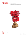
Electronic Valve Actuator
Model EVA-1
RCV-UM-00566-EN-01 (March 2015)
User Manual
Electronic Valve Actuator, Model EVA-1
CONTENTS
Description . . . . . . . . . . . . . . . . . . . . . . . . . . . . . . . . . . . . . . . . . . . . . . . . . . . . . . . . . . . . . . . . . . . . . . . . . . 3
Unpacking & Inspection . . . . . . . . . . . . . . . . . . . . . . . . . . . . . . . . . . . . . . . . . . . . . . . . . . . . . . . . . . . . . . . 3
Storage . . . . . . . . . . . . . . . . . . . . . . . . . . . . . . . . . . . . . . . . . . . . . . . . . . . . . . . . . . . . . . . . . . . . . . . . . . 3
Identification Label . . . . . . . . . . . . . . . . . . . . . . . . . . . . . . . . . . . . . . . . . . . . . . . . . . . . . . . . . . . . . . . . . . 3
Safety . . . . . . . . . . . . . . . . . . . . . . . . . . . . . . . . . . . . . . . . . . . . . . . . . . . . . . . . . . . . . . . . . . . . . . . . . . . . . 4
Operation . . . . . . . . . . . . . . . . . . . . . . . . . . . . . . . . . . . . . . . . . . . . . . . . . . . . . . . . . . . . . . . . . . . . . . . . . . . 4
Ratings . . . . . . . . . . . . . . . . . . . . . . . . . . . . . . . . . . . . . . . . . . . . . . . . . . . . . . . . . . . . . . . . . . . . . . . . . . . . . 4
Specifications . . . . . . . . . . . . . . . . . . . . . . . . . . . . . . . . . . . . . . . . . . . . . . . . . . . . . . . . . . . . . . . . . . . . . . . . 5
Electrical . . . . . . . . . . . . . . . . . . . . . . . . . . . . . . . . . . . . . . . . . . . . . . . . . . . . . . . . . . . . . . . . . . . . . . . . . 5
Mechanical . . . . . . . . . . . . . . . . . . . . . . . . . . . . . . . . . . . . . . . . . . . . . . . . . . . . . . . . . . . . . . . . . . . . . . . 5
Installation and Setup . . . . . . . . . . . . . . . . . . . . . . . . . . . . . . . . . . . . . . . . . . . . . . . . . . . . . . . . . . . . . . . . . . . 6
Adjustments . . . . . . . . . . . . . . . . . . . . . . . . . . . . . . . . . . . . . . . . . . . . . . . . . . . . . . . . . . . . . . . . . . . . . . 7
Final Assembly . . . . . . . . . . . . . . . . . . . . . . . . . . . . . . . . . . . . . . . . . . . . . . . . . . . . . . . . . . . . . . . . . . . . . 8
Maintenance . . . . . . . . . . . . . . . . . . . . . . . . . . . . . . . . . . . . . . . . . . . . . . . . . . . . . . . . . . . . . . . . . . . . . . 8
Wiring Connections . . . . . . . . . . . . . . . . . . . . . . . . . . . . . . . . . . . . . . . . . . . . . . . . . . . . . . . . . . . . . . . . . . . . . 9
USB to RS-232 Converter . . . . . . . . . . . . . . . . . . . . . . . . . . . . . . . . . . . . . . . . . . . . . . . . . . . . . . . . . . . . . . . . . 9
Items Required . . . . . . . . . . . . . . . . . . . . . . . . . . . . . . . . . . . . . . . . . . . . . . . . . . . . . . . . . . . . . . . . . . . . . 9
Driver Installation . . . . . . . . . . . . . . . . . . . . . . . . . . . . . . . . . . . . . . . . . . . . . . . . . . . . . . . . . . . . . . . . . . . . . 10
Software Configuration . . . . . . . . . . . . . . . . . . . . . . . . . . . . . . . . . . . . . . . . . . . . . . . . . . . . . . . . . . . . . . . . . 13
EVA-1 Terminal Emulator Menu Advanced Configuration . . . . . . . . . . . . . . . . . . . . . . . . . . . . . . . . . . . . . . . . . 14
Page ii
RCV-UM-00566-EN-01
March 2015
Description
DESCRIPTION
The Model EVA-1 is a small, electronically controlled, valve actuator developed specifically to fit 1/4 inch to 1 inch
Research Control Valves. Its accurate positioning and compact size make it especially suited to flow control in research and
small process applications. The unit features:
•
Microprocessor-controlled, linear stepper motor
•
4…20 mA analog input
•
Position 4…20 mA analog output (optional)
•
Choice of 12 speeds
•
Up to 40 pounds of stem thrust
•
Accurate and repeatable positioning
•
Adjustable split range
•
Quick and simple zero and span input and output adjustments
•
Adjustable stroke range 0.1875…0.5625"
•
User adjustable direct or reverse action
•
RS-232 Serial Port for all adjustments without removing the cover*
•
Controlled seating force to prevent innervalve damage
•
Built-in temperature compensation
•
Stainless steel yoke and rugged epoxy coated aluminum housing
• 115V AC/12V DC, 230V AC/12V DC, and 24V DC models available
* Not Explosion Proof when RS-232 port is uncovered or when cover is removed.
Unpacking & Inspection
Upon opening the shipping container, visually inspect the product and applicable accessories for any physical damage such
as scratches, loose or broken parts, or any other sign of damage that may have occurred during shipment.
NNOTE: If damage is found, request an inspection by the carrier’s agent within 48 hours of delivery and file a claim with the
carrier. A claim for equipment damage in transit is the sole responsibility of the purchaser.
Storage
If the product will not be installed immediately, it should be stored in a clean, dry area where the ambient temperature is not
less than –20° F (–30° C). The actuator should be stored in a non-corrosive environment. The actuator is not sealed to NEMA 4
until the conduit entries are properly connected.
Identification Label
An identification label is attached to each actuator cover. When ordering parts, requesting information or service assistance,
provide all of the label information.
March 2015
RCV-UM-00566-EN-01
Page 3
Safety
SAFETY
The installation of the EVA electric actuator must comply with all applicable federal, state, and local rules, regulations,
and codes.
Failure to read and follow these instructions can lead to misapplication or misuse of the product, resulting in personal injury
and damage to equipment.
• Read and save all instructions prior to installing, operating and servicing this product.
• Follow all warnings, cautions and instructions marked on, and supplied with, the product.
• Inform and educate personnel in the proper installation, operation and maintenance of the product.
• Install equipment as specified in the installation instructions and per applicable local and national codes. Connect all
products to the proper electrical sources.
• To ensure proper performance, use qualified personnel to install, operate, update, tune and maintain the product.
• When replacement parts are required, ensure that the qualified service technician uses factory replacement parts.
Substitutions may result in fire, electrical shock, other hazards, or improper equipment operation.
• Keep all product protective covers in place (except when installing, or when maintenance is being performed by qualified
personnel) to prevent electrical shock, personal injury or damage to the actuator.
SHOCK HAZARD! INSTALLATION AND SERVICING MUST BE PERFORMED ONLY BY QUALIFIED PERSONNEL.
ELECTROSTATIC DISCHARGE! THIS ELECTRONIC CONTROL IS STATIC-SENSITIVE. TO PROTECT THE INTERNAL
COMPONENTS FROM DAMAGE, NEVER TOUCH THE PRINTED CIRCUIT CARDS WITHOUT USING ELECTROSTATIC
DISCHARGE (ESD) CONTROL PROCEDURES.
OPERATION
The Model EVA-1 consists of a microprocessor-controlled, linear stepper motor that responds to an input signal of
4…20 mA DC. It also offers an optional isolated loop powered 4…20 mA position output for signaling back to an indicator
or control panel. The standard Model EVA-1 requires a 115V AC power supply with 230V AC and 24V DC models available.
A stroke of 0.437 inches for the 1/4" unit or a stroke of 0.562 inches for the 1/2" to 1" units is standard and can be adjusted
quickly and easily with two switches under the actuator cover or via the communication port. This ease of calibration can be
used to split range the input or limit the up or down travel of the valve. The unit utilizes a “dual speed” operating mode. The
low speed mode generates high thrust for seating the valve and overcoming packing friction while the high speed mode
allows the valve to respond quickly to large input signal changes.
RATINGS
• NEMA 4, Watertight
• Explosion-proof* Class 1, Division 1, Groups C & D
• Standard models approved by both FM and CSA
* Not explosion-proof when RS232 is uncovered or when cover is removed.
Page 4
RCV-UM-00566-EN-01
March 2015
Specifications
SPECIFICATIONS
Electrical
Supply Power/Standard
115V AC +/– 10% @ 50…60 Hz and/or 12V DC
Supply Power/Optional
230V AC +/– 10% @ 50…60 Hz and/or 12V DC 24V DC +/– 3%
Control input
4…20 mA DC @ 125 ohms
Position Output
4…20 mA DC isolated, 0…800 Ohm loop impedance
Mechanical
Stroke Length
Up to 0.562" (adjustable)
Thrust
40 lb at minimum step rate; 10 lb at maximum step rate
(See “Figure 2: Output vs speed” on page 8)
Height
13 inches (actuator with yoke only)
Weight
12 pounds (actuator with yoke only)
Operating Temperature Range
–10…60° C
March 2015
RCV-UM-00566-EN-01
Page 5
Installation and Setup
INSTALLATION AND SETUP
Qualified personnel must perform all wiring in accordance with prevailing codes.
Fusing must be installed in line power, and should be of the slow-blow type. Badger Meter recommends 1 amp for AC input
models and 5 amp for DC input models.
Route the wiring to the actuator through one of the two 1/2 inch conduit openings. Generally, one conduit contains input
power and earth ground wires. The other conduit contains low level input and output signal wiring.
All low level signal wiring should be a shielded type with the shield grounded at source common. After installation, seal all
conduits to prevent water damage.
Strip 0.22 inch (5.6 mm) of insulation from the wire and insert the bare end into the appropriate terminal location, using an
insertion tool or a small screwdriver.
During installation, refer to the location of parts listed in Figure 1.
Output signal
Input signal
Span/zero switch
Travel switch
Control logic PCB
Power supply PCB
Power terminal block
Setup/service port
Power port
Signal port
Actuator stem connector
Travel scale
Travel pointer locknut
Trim stem connector
Figure 1: EVA parts
1. Remove the cover using an adjustable open-end wrench on the hex protrusion at the top or a strap wrench around the
ribbed section. The yoke should be clamped in a vise, or a short piece of 1/2 inch NPT pipe may be inserted in the
setup/service port to resist the torque applied to the cover.
2. Connect to the Valve:
a. Apply power to the Power Terminal Block. For dual-power versions, the power line must be equipped with a slow-blow
fuse rated at 1 ampere if 12V DC is applied, 1/4 ampere for 115V AC, or 1/8 ampere for 230V AC. The 24V DC versions
require 1 ampere fuses.
NNOTE: AC versions built before January 1, 1989 required smaller fuses. Check original documentation for correct sizes.
b. Thread the Travel Pointer locnut up the actuator stem. Activate the Travel Switch to cause the actuator to stroke full
open. Remove power.
c. Install the EVA-1 on the valve bonnet with the yoke locknut supplied with the valve. Do not secure.
d. The Stem Connector should be locked to the valve stem by the interference threads. Thread the actuator stem into
the Stem Connector until it contacts the valve stem. The entire actuator must be rotated if attached to a bellows- or
diaphragm- type seal valve. Tighten the yoke locknut using the appropriate yoke locknut wrench. Secure the travel
pointer locknut across the Travel Pointer.
Page 6
RCV-UM-00566-EN-01
March 2015
Installation and Setup
3.Interconnection
a. With the valve and actuator assembly installed in the process line, connect conduit to the Power and Signal Ports. It is
recommended that wire be in place in the conduit and inserted into the EVA-1 base before this connection is made.
b. Install the power wires in the Power Terminal Block. Route the wires below the terminal and against the Power Supply
Printed Circuit Board. The power line must be equipped with a fuse per step 2a above.
c. Install the input and output (optional) signal wires to the Signal Terminal Blocks. Observe the polarity indicated on
the connectors.
Adjustments
For Zero Position and Span Position, P1 jumper must be set as shown at right:
Zero Position
1.
2.
3.
4.
5.
Apply power to the EVA-1.
Apply a signal corresponding to a VALVE CLOSED position to the Input Signal terminals.
Move the Travel Switch to the DOWN position until a pulsating noise indicates the valve trim is closed.
Release the Travel Switch and move the Span/Zero switch down to enter this position into the EVA-1 memory.
Adjust the Travel Scale to make the CLOSED arrow indicate opposite the Travel Pointer.
P1
Span Position
1. Apply a signal corresponding to a VALVE OPEN position to the Input Signal terminals.
2. Move the Travel Switch to the UP position and observe the Travel Pointer. Release the switch when the full open position
is reached.
3. Move the Span/Zero Switch up to enter this position in the EVA-1 memory.
Output Zero Setting (Optional)
1. The EVA-1 must have power applied, the output loop must be powered (12…48V DC) and the display device
indicating output must be within view.
2. Apply the input signal current to the actuator necessary to drive the valve closed.
3. Move the jumper to the position shown at right. Use the Travel Switch to adjust the current to 4 mA.
4. When the desired current is reached, store the value by pushing the Span/Zero Switch to Zero.
March 2015
RCV-UM-00566-EN-01
P1
Page 7
Installation and Setup
Output Span Setting (Optional)
1.
2.
3.
4.
Apply the input signal current to the actuator necessary to drive the valve to the desired full-open position.
Move the jumper to the position shown at right. Use the Travel Switch to adjust this current to 20 mA
When the desired current is reached store the value by pushing the Span/Zero Switch to Span.
Place the jumper in the position shown at right for normal operation.
P1
P1
Figure 2: Output vs speed
Final Assembly
1. Apply a liberal amount of lubricant (Dow Corning Gn Paste is recommended) to the EVA-1 housing threads and
O-ring seal.
2. Carefully thread the cover to the housing and secure.
3. Fasten the bracket at the base of the actuator to an adjacent supporting structure.
4. Secure the plug in the Setup/Service port to meet NEMA specifications.
Maintenance
Although the EVA-1 is designed to be trouble-free for its entire service life, the motor lead-screw shaft may require lubrication
if the unit is subjected to severe service.
To lubricate the shaft:
1. Remove the yoke and run the shaft out the bottom of the actuator.
2. Record the orientation of the square portion of the stem connector assembly with respect to the actuator base.
3. Clean the shaft thoroughly and re-coat with Dow Corning Gn Paste.
4. To re-assemble the actuator, orient the unit so the base is facing up.
5. Re-install the stem connector assembly and yoke by reversing the above steps.
6. Allow the yoke to center on the stem connector assembly before tightening the 4 yoke fasteners.
Alignment of the yoke with the center axis of the motor is crucial to allow free running of the stem connector assembly within
the yoke bore.
Page 8
RCV-UM-00566-EN-01
March 2015
Wiring Connections
WIRING CONNECTIONS
Figure 3: Wiring connections
USB TO RS-232 CONVERTER
The USB to RS-232 converter facilitates the connection of legacy RS-232 products to the modern USB-equipped host PCs
for the purposes of configuration and test. Peripherals used with the USB to RS-232 converter include the host PC and
the connected valve actuator. The USB to RS-232 converter is typically only connected during the configuration of the
valve actuator.
Figure 4: Diagram of the intended application for the USB to RS-232 converter
Items Required
• USB to RS-232 converter module (1)
• Badger Meter product featuring an RS-232 serial interface
• USB cable with ferrites and A connector to mini-USB (1)
• Terminal emulator with VT52 emulation
• Access to FTDI drivers (within the Windows® driver base, or on the included CD/DVD, or from the FTDI site:
http://www.ftdichip.com/FTDrivers.htm)
March 2015
RCV-UM-00566-EN-01
Page 9
Driver Installation
DRIVER INSTALLATION
1. Download and install a terminal emulator similar to HyperTerminal®. This action requires administrative privileges.
2. If you are using a device with a legacy or non-Internet connected version of Windows®, download and extract the
appropriate FTDI driver package from the FTDI website. Copy these files to a convenient location so you can find them
during the driver installation process.
3. Plug the USB cable and the USB to RS-232 converter into a free port on the host PC.
4. When prompted about the Windows Update driver installation, select Yes only if the PC is connected to the Internet, as
shown in Figure 5.
Figure 5: Driver installation from the Internet, for Internet-connected PCs only
5. Select Install USB Converter Software Automatically only if the PC is connected to the Internet, as displayed in Figure 6.
Figure 6: Automatic installation of the drivers, for Internet-connected PCs only
6. Alternately, if the PC used with the USB to RS-232 converter is not internet connected, or is running a legacy (pre XP)
version of the Windows operating system, it may be easier to download the FTDI driver package to a flash drive,
CD-ROM or floppy disk.
Page 10
RCV-UM-00566-EN-01
March 2015
Driver Installation
7. To facilitate the off-line installation of the drivers, select No to the search Windows Update prompt, as shown in Figure 7.
Figure 7: Selection of an off-line installation of the FTDI driver files
8. Next, opt for a specific location at the automated installation prompt, as shown in Figure 8.
Figure 8: Opt out of the automated installation
9. When prompted about a specific location to check for the FTDI drivers, check Include this search location and browse to
the location of the extracted FTDI driver package, as displayed in Figure 9.
Figure 9: Include a relevant search path
10.If a prompt appears warning about the lack of Windows logo testing, opt to Continue Anyway, as shown in Figure 10.
March 2015
RCV-UM-00566-EN-01
Page 11
Driver Installation
Figure 10: Opt to continue despite the lack of Windows® logo testing
11.A status bar indicates that the driver files are being copied to the required destination. Subsequently, the final prompt
indicates that the processes either succeeded or failed, as shown in Figure 11 and Figure 12.
Figure 11: Status bar stating that the files are being copied
Figure 12: Successfully finished the driver installation
12.An additional driver installation prompt requests the installation of a USB Serial Port driver. Repeat the installation process
starting at step 3.
Page 12
RCV-UM-00566-EN-01
March 2015
Software Configuration
SOFTWARE CONFIGURATION
1. Prior to the configuration and use of the RS-232 combo software, determine the proper COM port. To do this, start the
device manager by selecting Start > Run, and typing "devmgmt.msc" in the run dialog box, as shown in Figure 13.
Figure 13: Starting the device manager from the run dialog
2. Next, determine the COM port number assigned to the USB serial port by checking the enumeration under the device
manager ports listing. For the installation shown in Figure 14, this number is 10. For other installations and computers, this
number will be different.
Figure 14: The device manager ports listing, with the USB serial port identified as COM 10
3. Subsequently, the terminal emulator software is configured to use the COM port number of the USB serial port, as detailed
in the software documentation or help file for use with the terminal emulator similar to HyperTerminal.
4. Configure the terminal emulator with the following settings:
Baud: 9600
Data bits: 8
Stop bit: 1
Parity: n
Flow cont: none
Emulation: VT-52
5. Refer to the commands on page 1 for use with the connected device.
March 2015
RCV-UM-00566-EN-01
Page 13
Software Configuration
EVA-1 Terminal Emulator Menu Advanced Configuration
Adjusting the 4-20 mA Zero Output
1. Press M until 4-20 Zero out adj w/Arrow keys displays.
2. Use the U and D keys to change the value.
NNOTE: You must connect an ammeter to the output terminals and connect the power supply to the input terminals of EVA-1
to see a change in the current. Also must be calibrated before changing.
3. Press E to accept changes, or M to cancel and move to the next menu.
Adjusting the 4-20 mA Span Output
1. Press M until 4-20 Zero out adj w/Arrow keys displays.
2. Use the U and D keys to change the value.
NNOTE: You must connect an ammeter to the output terminals and connect the power supply to the input terminals of EVA-1
to see a change in the current. Also must be calibrated before changing.
3. Press E to accept changes, or M to cancel and move to the next menu.
Adjusting the Actuator Speed
1. Press M until ACTUATOR SPEED – steps/second displays.
2. Use the U and D keys to change the value up and down respectively.
3. Press E to accept changes, or M to cancel and move to the next menu.
Checking the Input Signal
1. Press M until INPUT SIGNAL – % Full Scale displays.
2. The percentage of full scale displays on the bottom line of the terminal window.
3. Press M to move to the next menu.
Checking the Internal Temperature
1. Press M until Internal Temp- Degrees C displays.
2. The temperature displays in degrees Celsius.
NNOTE: The first time you access this menu, please allow a few moments for the value to stabilize.
3. Press M to move to the next menu.
Checking the Motor Current
1. Press M until Motor Current- mA per phase displays.
2. The motor current displays on the bottom line in milliamps per phase.
NNOTE: The first time you access this menu, please allow a few moments for value to stabilize.
3. Press M to move to the next menu.
Adjusting the Servo Deadband
1.
2.
3.
4.
Press M until Servo Deadband - % Stem Travel displays.
Use the U or D keys or the left arrow key to adjust.
Set to a percentage in the range of 0-1% by 0.1% increments.
Press E to send data to EVA-1 or M to cancel and move to the next menu.
Running a Diagnostics Test
1. Press M until Diagnostics – Key Enter to Begin displays.
2. Press E to run Diagnostics.
3. Upon completion, press M to move to the next menu.
Page 14
RCV-UM-00566-EN-01
March 2015
Software Configuration
Setting the Overdrive
1. Press M until Set Overdrive – <--- Enter displays.
2. Press D, U, or the left arrow key to change to ON or OFF.
3. Press E to enter data or press M to cancel and move to the next menu.
Viewing the Stem Position
1. Press M until Stem Position – % Travel displays.
2. The percentage of total position is displayed on the bottom line.
3. Press M to move to the next menu.
Applying a Zero Signal
1.
2.
3.
4.
Press M until Apply zero Signl Adj w/ Arrow keys displays.
Use D or the left arrow key to move the stem position down.
Use U to move the stem position up.
Press E to lock in the zero signal or press M to cancel and move to the next menu.
Applying a Span Signal
1.
2.
3.
4.
Press M until Apply Span Signl Adj w/Arrow keys displays.
Use D or the left arrow key to move the stem position down.
Use U key to move the stem position up.
Press E to lock in the span signal or press M to cancel and move to the next menu.
March 2015
RCV-UM-00566-EN-01
Page 15
Electronic Valve Actuator, Model EVA-1
Control. Manage. Optimize.
Research Control is a registered trademark of Badger Meter, Inc. Other trademarks appearing in this document are the property of their respective entities. Due to continuous
research, product improvements and enhancements, Badger Meter reserves the right to change product or system specifications without notice, except to the extent an
outstanding contractual obligation exists. © 2015 Badger Meter, Inc. All rights reserved.
www.badgermeter.com
The Americas | Badger Meter | 4545 West Brown Deer Rd | PO Box 245036 | Milwaukee, WI 53224-9536 | 800-876-3837 | 414-355-0400
México | Badger Meter de las Americas, S.A. de C.V. | Pedro Luis Ogazón N°32 | Esq. Angelina N°24 | Colonia Guadalupe Inn | CP 01050 | México, DF | México | +52-55-5662-0882
Europe, Middle East and Africa | Badger Meter Europa GmbH | Nurtinger Str 76 | 72639 Neuffen | Germany | +49-7025-9208-0
Europe, Middle East Branch Office | Badger Meter Europe | PO Box 341442 | Dubai Silicon Oasis, Head Quarter Building, Wing C, Office #C209 | Dubai / UAE | +971-4-371 2503
Czech Republic | Badger Meter Czech Republic s.r.o. | Maříkova 2082/26 | 621 00 Brno, Czech Republic | +420-5-41420411
Slovakia | Badger Meter Slovakia s.r.o. | Racianska 109/B | 831 02 Bratislava, Slovakia | +421-2-44 63 83 01
Asia Pacific | Badger Meter | 80 Marine Parade Rd | 21-06 Parkway Parade | Singapore 449269 | +65-63464836
China | Badger Meter | 7-1202 | 99 Hangzhong Road | Minhang District | Shanghai | China 201101 | +86-21-5763 5412
Legacy Document Number: 940910