1
Chapter 7. PARAMETER SETUP
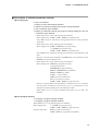
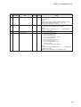
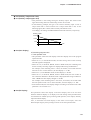
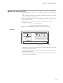
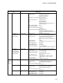
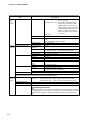
● C90 (special function)
• Normally, set to “0”.
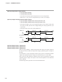
• When set to 102, the control output range 0 to 100% becomes 0 to 20 mA when
current output (including heat/cool output) is set as the output. However, note
that when control output is less than 0%, current output is 0 mA, and when
control output is less than 5%, the accuracy is ±0.5%.
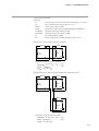
• When set to 103, the control output range 0 to 100% becomes 0 to 20 mA when
current output (including heat/cool output) and auxiliary output is set as the
output. However, note that when control output is less than 0%, current output is
0 mA, and when control output is less than 5%, the accuracy is ±0.5%.
• When set to 241, Zener barrier adjustment (C91) is displayed when the input 1
range type (C03) is an RTD.
• When set to 241, Zener barrier adjustment (C92) is displayed when the input 2
range type (C23) is an RTD.
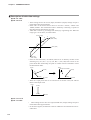
● C91 (input 1 Zener barrier adjustment)
● C92 (input 2 Zener barrier adjustment)
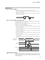
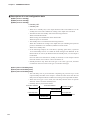
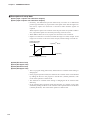
The following adjustment must be made when using a Zener barrier.
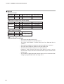
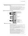
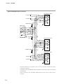
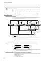
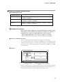
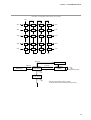
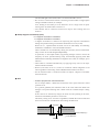
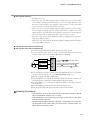
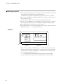
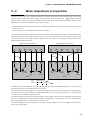
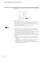
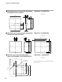
① Turn the DCP32 OFF. When you have finished mounting and wiring the
DCP32, short-circuit across the A and B terminals of the RTD.
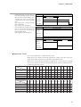
DCP32
Zener barrier
Zener barrier
Short-circuit
Zener barrier
C
B
A
32
33
34
Terminals 32 33 34 are for when input 1
is used.
In case of input 2, these terminals become
terminal 28 (terminal C), terminal 29
(terminal C) and terminal 30 (terminal A).
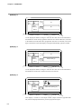
② Turn the DCP32 ON again, and set setup data C90 setting to 241. For details
on how to change settings, see “7-1 Parameter Setup” (page 7-1).
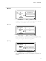
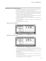
③ Display the setup data C91 or C92 setting.
④ Press the ENT key to display the difference (A-B) between the resistances of
the Zener barriers connected to leads A and B on the lower display.
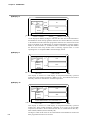
⑤ Press the ENT key to memorize the difference (A-B) between the resistances
on the DCP32.
⑥ Press the DISP key to set the DCP32 to the basic display state.
⑦ Turn the power OFF, and remove the short-circuit across A and B.
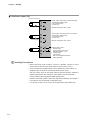
Handling Precautions
• The resistance error of the Zener barrier connected to leads A and B
cannot be adjusted unless it is 20 Ω or less.
• This adjustment is not required when a Zener barrier and an input other
than an RTD are not used.
• Once the Zener barrier has been adjusted, compensation is carried out
on the Zener barrier. When using an RTD without a Zener barrier, readjust without the Zener barrier.
7-43