1
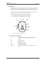
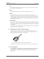
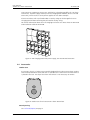
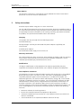
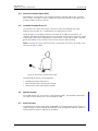
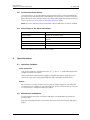
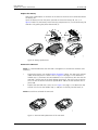
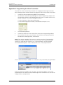
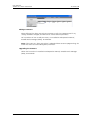
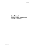
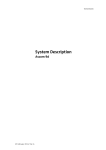
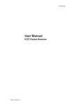
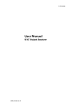
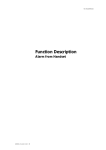
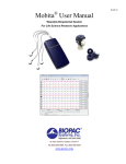
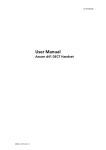
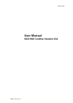
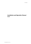
TD 92351GB
User Manual
Ascom a51 Alarm Transmitter
2007-03-15/ Ver. C
User Manual
Ascom a51 Alarm Transmitter
TD 92351GB
Contents
1 Introduction............................................................................................................. 1
1.1 Abbreviations and Glossary ................................................................................ 1
1.2 Ascom a51 Versions ........................................................................................... 2
2 Description............................................................................................................... 2
2.1 Ascom a51 Alarm Transmitter ............................................................................ 2
2.2 Single Charger for Ascom a51 Alarm Transmitter ............................................... 3
2.3 PCR Charging Rack ............................................................................................ 3
2.4 Accessories ........................................................................................................ 4
3 Safety Instructions .................................................................................................. 5
4 Basic Operation ....................................................................................................... 6
4.1 Switch the Alarm Transmitter On/Off .................................................................. 6
4.2 Mute the Beep/Vibrator/LED Signal .................................................................... 6
4.3 Charge the Battery ............................................................................................. 6
5 Alarm Functions ...................................................................................................... 7
5.1 Push-button Alarms ........................................................................................... 8
5.2 Pull-cord Alarm .................................................................................................. 8
5.3 Man-down & No-movement Alarm .................................................................... 8
5.4 Acoustic Location Signal (ALS) ............................................................................ 9
5.5 Location Function (IR or LF) ................................................................................ 9
5.6 Special location ................................................................................................ 10
5.7 External alarm .................................................................................................. 10
5.8 Deactivate/activate Alarms ............................................................................... 10
5.9 Show Status of the Alarm Transmitter .............................................................. 10
6 Operation Notice................................................................................................... 10
6.1 Operation Condition ........................................................................................ 10
6.2 Maintenance and Repairs ................................................................................. 11
7 Related Documents ............................................................................................... 12
8 Document History ................................................................................................. 13
Appendix A: Programming the Alarm Transmitter................................................ 14
2007-03-15/ Ver. C
User Manual
Ascom a51 Alarm Transmitter
1
TD 92351GB
Introduction
This document provides a description of the Ascom a51 Alarm Transmitter. The Alarm
Transmitter is described in default programmed version but additional functions and
factory settings are also included, providing a full description of the functionality.
Note that your system may not supply all functions described in this document. For
information about your system, please contact your supplier.
The following documents are recommended as a complement:
• System Description, Personal Security System, TD 90677GB
• System Description, On-site Paging System, TD 91034GB.
LED
Name label
(internal)
IR-receiver
Mute
button
Pull-cord
Soft-alarm
button
001
Alarm
button
1.
Figure
Figure 1. Ascom a51 Alarm Transmitter.
1.1
Abbreviations and Glossary
ALS
Acoustic Location Signal. A ramped up signal that can be
played after an alarm from an Alarm Transmitter.
IR
Infra Red
LED
Light Emitting Diode
LF
Low Frequency
PCR
Portable Charging Rack
PDM
Portable Device Manager
SIM
Subscriber Identity Module
System 900
Generic term for telePROTECT, teleCOURIER and CTS 900
systems.
2007-03-15/ Ver. C
1
User Manual
Ascom a51 Alarm Transmitter
1.2
TD 92351GB
Ascom a51 Versions
The a51 Alarm Transmitter included in the Personal Security System, is easy to carry and
operate and is designed to function in tough environments. It is available in two different
versions, basic and advanced:
Functions
a51 Basic
a51 Advanced
Push-button alarms
Yes
Yes
Pull-cord alarm
Yes
Yes
Vibrator alert
Yes
Yes
Man-down & No-movement alarm
No
Yes
Acoustic Location Signal (ALS)
No
Yes
Location function (IR and LF)
No
Yes
Battery check function
Yes
Yes
Alarms are transmitted on the UHF band 420-475 MHz. The code format is compatible
with the System 900, which means that functions and units from the two systems can be
integrated with each other.
2
Description
2.1
Ascom a51 Alarm Transmitter
Case
The case is made of durable PC/ABS plastic and is IP40 classified. The Alarm Transmitter
also fulfils IEC 68-2-32 procedure 1, which makes it drop proof from one meter onto
concrete.
Antenna
The antenna used for communicating with the fixed system is integrated in the Alarm
Transmitter. This makes the Alarm Transmitter robust and easy to handle.
Top
The transparent smoke coloured top covers the IR receiver, integral name label. On the top
is also the LED.
Buttons
The Alarm Transmitter has three buttons, see also figure 1 on page 1:
Alarm button, big button on the front of the handset, for sending alarm. The button can
also be used for test alarm. The function of this button is configurable.
Soft-alarm button, small button marked with "!"used as a request for discreet
assistance. The button can also be used for test alarm. The function of this button is
configurable.
Mute button, button on the right side, used to silence the beep, vibrator and LED signal
including the Acoustic Location Signal (ALS).
2007-03-15/ Ver. C
2
User Manual
Ascom a51 Alarm Transmitter
TD 92351GB
Clip
On the back of the Alarm Transmitter there is a clip used to fasten the Alarm Transmitter
to, for example, the belt or pocket.
Battery
The battery placed behind the battery lid is a rechargeable Li-Ion battery.
SIM Card
All personal settings in the Alarm Transmitter are programmed and stored in the
Subscriber Identity Module (SIM) card. The SIM card can easily be moved to another Alarm
Transmitter. By this it is easy to keep personal settings, such as identity and alert signal.
This can be handy in case of break down or when changing operation environment and
switching Alarm Transmitter.
Pull-cord (Option)
The pull-cord is made of an ABS attachment connected to a canvas ribbon. The end of the
ribbon has a clip which must be safely attached, for example, to the clothes. The Pull-cord
is also used as a security string, which prevents the Alarm Transmitter to, for example, fall
on the ground.
The Alarm Transmitter can be used without the Pull-cord option. Remove the Pull-cord and
plug the hole with the provided ABS lid.
2.2
Single Charger for Ascom a51 Alarm Transmitter
002
The Single Charger is a separate unit used for charging the Alarm Transmitter. It is
connected to a power supply. The power supply has four exchangable plug-in contacts
which fit into an ordinary wall socket in many countries.
2.
Figure
Figure 2. Single Charger for Ascom a51 Alarm Transmitter.
For further information about the Single Charger refer to its Data Sheet TD 92353GB.
2.3
PCR Charging Rack
The wall mounted PCR Charging Rack is used for charging Ascom a51 Alarm Transmitters.
The Charging Rack is a modular system that consists of a master module (PCR-M),
extension modules (PCR-E) and power supplies. Each Charging Rack module has six
charging slots.
2007-03-15/ Ver. C
3
User Manual
Ascom a51 Alarm Transmitter
TD 92351GB
One PCR-M can support up to 20 PCR-E, which gives a charging possibility of 126 Alarm
Transmitters. A power supply feeds up to three Charging Rack modules (one PCR-M and
two PCR-E), which results in seven power supplies for the above example.
Alarm Transmitters with a pull-cord and/or a security string can be charged in the PCR
Charging Rack without removing the pull-cord or security string.
003
For further information about the PCR Charging Rack refer to its Data Sheet TD 92355GB
and Installation Guide TD 92356GB.
3.
Figure
Figure 3. PCR Charging Rack with power supply, one PCR-M and two PCR-E.
2.4
Accessories
Leather case
004
As accessory, there is a leather case especially designed for the Alarm Transmitter used to
increase the protection of wear and tear. It is possible to use the Alarm Transmitter while it
is placed in the case. The clip of the Alarm Transmitter is not neccessary to remove.
4.
Figure
Figure 4. Leather case for the Ascom a51 Alarm Transmitter.
Security String
See Pull-cord (Option) on page 3.
2007-03-15/ Ver. C
4
User Manual
Ascom a51 Alarm Transmitter
TD 92351GB
Name label kit
For the Alarm Transmitter, a name label kit can be ordered. The internal name label is
possible to use for own means of identification.
3
Safety Instructions
Read this chapter before using your a51 Alarm Transmitter.
For safe and efficient operation of your Alarm Transmitter, observe the guidelines given in
this manual and all necessary safety precautions when using the Alarm Transmitter. Follow
the operating instructions and adhere to all warnings and safety precautions located on
the product, the Quick Reference Guide and this User Manual.
Charging
This product shall only be used with the following batteries:
P/N: 660089 Battery
Desktop chargers shall only be connected with power adapters supplied by the
manufacturer.
Available power adapter:
P/N: FW7650/05 Power supply unit AC/5V DC/1A
Warranty notification
Do not disassemble the Alarm Transmitter. Disassembling the handset voids the warranty.
The a51Alarm Transmitter consists of no consumer serviceable components. Service
should be performed only by Authorized Service centre.
Modifications
Changes or modifications to the equipment not expressly approved by the party
responsible for compliance could void the user’s authority to operate the equipment.
FCC compliance statements
This equipment has been tested and found to comply with the limits for a Class B digital
device, pursuant to part 15 of the FCC Rules. These limits are designed to provide
reasonable protection against harmful interference in a residential installation. This
equipment generates, uses and can radiate radio frequency energy and, if not installed
and used in accordance with the instructions, may cause harmful interference to radio
communications. However, there is no guarantee that interference will not occur in a
particular installation. If this equipment does cause harmful interference to radio or
television reception, which can be determined by turning the equipment off and on, the
user is encouraged to try to correct the interference by one or more of the following
measures:
• Reorient or relocate the receiving antenna.
• Increase the separation between the equipment and receiver.
• Connect the equipment into an outlet on a circuit different from that to which the
receiver is connected.
• Consult the dealer or an experienced radio/TV technician for help.
2007-03-15/ Ver. C
5
User Manual
Ascom a51 Alarm Transmitter
TD 92351GB
Information to user
This device complies with Part 15 of the FCC Rules. Operation is subject to the following
two conditions:
(1) this device may not cause harmful interference, and
(2) this device must accept any interference received, including interference that may
cause undesired operation.
4
Basic Operation
Note: The Ascom a51 Alarm Transmitter may have functions other than described here,
depending on the pre-programmed parameters.
4.1
Switch the Alarm Transmitter On/Off
Insert/remove the battery.
4.2
Mute the Beep/Vibrator/LED Signal
Press the Mute button.
4.3
Charge the Battery
Three battery levels exist:
• OK
• Warning
• Shutdown
During the battery warning phase, a beep signal played once each 10 s. during one
minute and a fast flashing red LED indicates a low battery. Place the Alarm Transmitter in a
Single Charger or a wall mounted Charging Rack. If a Charging Rack is used for charging,
just insert the Alarm Transmitter without opening the clip, to make it fasten securely. Be
sure to hear a beep and see the LED charging indication when inserting the Alarm
Transmitter in the charging rack.
A slowly flashing orange LED indicates charging. A green steady LED indicates a fully
charged battery. It takes approximately two hours to fully charge the battery. Note that it is
normal for the battery to get slightly warm while charging.
If the battery level goes below the shutdown level, a shutdown warning beep is played for
10 s. after which the Alarm Transmitter enters deep sleep. The best way to wake up the
Alarm Transmitter from deep sleep is to put it into a Single Charger or wall mounted
Charging Rack. It is also possible to make a cold start, see 4.1 Switch the Alarm
Transmitter On/Off on page 6.
Note: While the Alarm Transmitter is attached to the Single Charger or put in the wall
mounted Charging Rack, only the push-button alarms (Alarm- and Soft-alarm button) and
the Pull-cord alarm are enabled. This means that, if existing, Man-down & No-movement
alarms are deactivated. The Location Function (IR and LF) is also deactivated. (If a push-
2007-03-15/ Ver. C
6
User Manual
Ascom a51 Alarm Transmitter
TD 92351GB
button alarm is sent, the last stored location before charging the Alarm Transmitter, is
sent).
Note: If the Alarm Transmitter is put into the charger during the shutdown warning beep,
the beep will stop and the Alarm Transmitter will not enter deep sleep at this time.
Note: Check the battery status every time you start to use the Alarm Transmitter. It is
recommended that the Alarm Transmitter is charged daily. This is even more important
when the Alarm Transmitter is used in temperatures below 0ºC.
5
Alarm Functions
In order to assure a safe transmission of an alarm to the system, every alarm is sent in two
sequences. The number of times to resend an alarm in each sequence is configurable with
parameters.
A beep/vibrator/LED signal can confirm that an alarm has been sent. These feedback
signals of a sent alarm are all configurable.
The alarms are handled by FIFO (First In First Out) and thus no alarm prioritation is made by
the system.
Common alarm configurations
The following parameters are common for the Test alarm, Alarm, Soft-alarm, Man-down &
No-movement and Pull-cord alarm types.
•
•
•
•
•
5.1
Number of alarm transmissions per sequence
Beep feedback
LED feedback
Vibrator feedback
Alarm deactivation (Only Man-down & No-movement alarm)
Push-button Alarms
Test alarm
Press the Alarm- or Soft-alarm button for at least one second. Depending on set
parameters, a beep is heard, the green LED flashes once and the vibrator stirs.
Note: To test the Alarm Transmitter and system, a test alarm should be sent every day.
Alarm
Press the Alarm push-button twice or more. Depending on set parameters, a beep is
heard, the green LED flashes once and the vibrator stirs.
Soft-alarm
This alarm can be used as a request for discreet assistance.
Press the Soft-alarm push button twice or more. Depending on set parameters, a beep is
heard, the green LED flashes once and the vibrator stirs.
2007-03-15/ Ver. C
7
User Manual
Ascom a51 Alarm Transmitter
TD 92351GB
Configuration of push-button alarms
The following parameters are configurable:
•
•
•
•
•
5.2
Alarm type for multiple press
Alarm type for single press (long press 1 s. by default)
Time of push-button press for single press
Number of presses for multiple press alarm
ALS
Pull-cord Alarm
An alarm is sent when the pull-cord is pulled off the Alarm Transmitter. Depending on set
parameters, a beep/vibrator/LED signal confirms that the alarm has been sent.
Note: Make sure that the clip of the Pull-cord is safely attached to the clothes. To make a
test, remove the battery of the Alarm Transmitter, pull the Alarm Transmitter and make
sure that the pull-cord releases first.
Configuration of Pull-cord Alarm
• ALS
5.3
Man-down & No-movement Alarm
Man-down alarm: The Alarm Transmitter is tilted more than 55º for a preset time, for
example when falling.
No-movement alarm: Movement is not detected during a pre-set time.
Before the alarm is sent, the Alarm Transmitter enters a warning phase called Man-down/
No-movement Warning (MDW), with a repeated warning tone (default: 7 seconds). The
beep signal always starts with a pair of low volume beeps and then continues with high
volume beeps, and is alternating with the vibrator.
Press the Mute button during this warning phase to prevent the alarm from being sent.
If the Mute button is not pressed an alarm is sent. Depending on set parameters, a beep/
vibrator/LED signal confirms that the alarm has been sent.
Extra Delay
If the parameter “Extra delay” is enabled, the detection of Man-down & No-movement
alarm can be disabled for 10 minutes. When the warning signal sounds, press and hold
the Mute button to delay the next warning signal 10 minutes. One long beep followed by
vibrator indicates that the Extra delay is set.
Configuration of Man-down & No-movement Alarm
The following parameters are configurable:
•
•
•
•
•
Time of Man-down detection phase (time of a tilted state)
Time of No-movement detection phase (time of a non moving state)
Time of Man-down/No-movement Warning (MDW) phase
ALS activation
Extra delay activation
2007-03-15/ Ver. C
8
User Manual
Ascom a51 Alarm Transmitter
5.4
TD 92351GB
Acoustic Location Signal (ALS)
Depending on set parameters, the ramped up Acoustic Location Signal (ALS) is played
after an alarm. The signal is always ramped from the lowest volume to the highest. Press
the Mute button to turn the ALS off.
5.5
Location Function (IR or LF)
The location of the Alarm Transmitter, received via either infrared light (IR) or low
frequency transmission (LF), is automatically sent along with an alarm.
If both IR and LF are enabled, the Alarm Transmitter first handles IR and then LF. If a
location is detected, the location function is put to sleep until the next scan interval, which
is defined by a parameter. Depending on set parameters, a beep signal and/or a flashing
green LED indicates that a location (a new or the same) has been received.
005
Note: An Ascom a51 Alarm Transmitter with an IR-receiver must always be visible, never
covered, see figure 5 below.
5.
Figure
Figure 5. IR-function of Alarm Transmitter.
The following parameters are configurable:
• Reading of location code interval
• Beep activation when receiving the location
• LED activation when receiving the location
5.6
Special location
If the fixed locators are set to send a "special location code", the portable automatically
can send an alarm directly after it has received the code.
5.7
External alarm
The portable can send an alarm when triggered by an incoming external alarm signal. A
Single Charger has to be modified for this purpose, see Configuration Manual, Ascom a71
Alarm Transceiver and p71 Transceiver, TD 92439.
2007-03-15/ Ver. C
9
User Manual
Ascom a51 Alarm Transmitter
5.8
TD 92351GB
Deactivate/activate Alarms
If this parameter is set, the Man-down & No-movement alarm can be turned off/on by
pressing twice on the Mute button. Depending on set parameters, a beep is heard, the
green LED flashes twice and the vibrator stirs when indicating deactivation/activation of
alarms. See also 5.9 Show Status of the Alarm Transmitter below.
Note: The Alarm and Soft-alarm push-buttons and Pull-cord alarm are always enabled.
5.9
Show Status of the Alarm Transmitter
LEDs
Status
Green steady:*
Battery OK, all alarms active.
Green slow flashing:*
Battery OK, Man-down/No-movement alarm
deactive.
Red fast flashing:*
Low battery indication
Red steady:
Fatal error
Orange flashing:
Charging
*Press and hold the Mute button to see the status.
6
Operation Notice
6.1
Operation Condition
Alarm Transmitter
Only use the handset in temperatures from -10 o C to +55 oC. Avoid exposing in direct
sunlight and other heat sources.
Protect your Alarm Transmitter from aggressive liquids and vapours. Keep the Alarm
Transmitter away from strong electromagnetic fields and explosive environments.
Battery
Do not immerse in water or throw into fire. Use the Single Charger or wall mounted
Charging Rack for charging. Charge the battery for at least two hours the first time you
use it. See also 4.3 Charge the Battery on page 6.
6.2
Maintenance and Repairs
Use only original accessories. Installation and repairs should be done by authorised
personnel only.
Keep the recharging contacts on the Alarm Transmitter away from metallic and greasy
objects.
2007-03-15/ Ver. C
10
User Manual
Ascom a51 Alarm Transmitter
TD 92351GB
Replace the Battery
Two plastic, ribbed plates at the back of the Alarm Transmitter are used to lock/unlock
the battery lid.
Open the battery lid: Pull the plates upwards to release the battery lid, see (1) in
figure 6 below. Put the battery into the battery compartment (2). Put on the battery lid
and close it by pulling the plates downwards (3).
Figure 6.
Note!
2
1
3
006
Note!
Figure 6. Battery replacement.
Remove the SIM Card
Note: It is recommended that the SIM card is changed in an environment without static
electricity.
1
Remove the battery, see section Replace the Battery above. The SIM card is placed
under the battery unit in a hatch. See 1 in figure 7 on page 11: Press down the
flexible stop (1) and move the SIM card back as far as possible (2). Be sure that the
SIM card is entirely out of the hatch before removing it. The easiest way to ensure
this is to turn the Alarm Transmitter upside down and let the SIM card falls out in
your hand.
2
Replace the SIM card with a new, see 2 in figure 7 on page 11: Put down the SIM
card so it lies flat on the flexible stop (1) and push it carefully into the hatch (2).
Note: Be careful not to bend the SIM card.
1
1
2
2
1
7.
007
2
Figure
Figure 7. Removal and replacement of the SIM card.
2007-03-15/ Ver. C
11
User Manual
Ascom a51 Alarm Transmitter
TD 92351GB
Replace the Name Label
Open the battery lid, see section Replace the Battery above, replace the old name label
with a new from the Name label kit (extra ordered).
Restore the Clip
The clip has a special release function to prevent it from breaking when strained. When
the clip is released and becomes slack, just snap it back with a hard press.
If the clip has fallen entirely off its fastening, perform the following:
1
Put the axle of the link clip in the closed hole on the clip, see 1.
2
Push the axle until it snaps into the open hole in the clip.
3
Snap the clip to the Alarm Transmitter with a hard press.
Figure 8.
2
3
009
1
Figure 8. How to restore the clip.
7
Related Documents
Installation and Operation Manual, Portable Device Manager
2007-03-15/ Ver. C
TD92325GB
12
User Manual
Ascom a51 Alarm Transmitter
8
TD 92351GB
Document History
For details, see change bars in the document.
Version
Date
A
2006-04-03 First released version
B
2006-05-09 Minor updates
C
2007-03-15 Update with safety instructions, special location and
external alarm
2007-03-15/ Ver. C
Description
13
User Manual
Ascom a51 Alarm Transmitter
TD 92351GB
Appendix A: Programming the Alarm Transmitter
The Ascom a51 Alarm Transmitter parameters can be programmed using the Portable
Device Manager (PDM) software PDM-SB. To program the Alarm Transmitter do as below:
1
Connect the RS232 Programming Adapter to the computer.
2
The computer COM port corresponding to the RS232 Programming Adapter and
the COM port settings for the PDM software must match. The PDM software uses
default COM port 1, but can be changed as follows:
1) In the Start menu, select PDM Configuration.
2) In the PDM Configuration window, select desired COM port > Save.
9.
Figure
3
Start the PDM application.
4
Connect the Ascom a51 Alarm Transmitter to the RS232 Programming Adapter.
5
For instructions on how to use the PDM, see Installation and Operation Manual,
Portable Device Manager (PDM), TD 92325GB.
Note: If the software upgrade of the Ascom a51 Alarm Transmitter is interrupted, for
example if the cable is removed, the a51 Alarm Transmitter turns to download mode
(shown by a steady red LED). When the a51 is connected again, the New portable
connected window appears. Select "Edit but don´t save"> OK, see figure below.
10.
Figure
The a51 Alarm Transmitter is added as an "unknown" entry in the PDM, see figure below.
11.
Figure
Repeat the software upgrade for this unit again. The software upgrade is successfully
performed when the Call No. of the portable changes from <unknown> to its real Call No.
and gets online, see figure below.
2007-03-15/ Ver. C
14
User Manual
Ascom a51 Alarm Transmitter
12.
TD 92351GB
Figure
Editing Parameters
When delivered, the Alarm Transmitter parameters usually is pre-programmed. If any
settings should be changed, the PDM can be used to edit the parameters.
For instructions on how to edit parameters, see Installation and Operation Manual,
Portable Device Manager (PDM), TD 92325GB.
Note: If the ascom a51 Alarm Transmitter is ordered without customer programming, the
UserID has to be set before editing other parameters.
Upgrading the Firmware
Follow the instructions in Installation and Operation Manual, Portable Device Manager
(PDM), TD 92325GB.
2007-03-15/ Ver. C
15