1
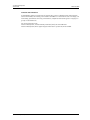
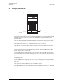
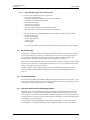
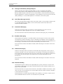
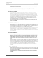
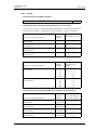
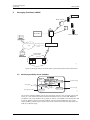
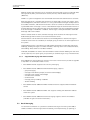
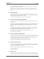
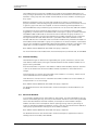
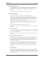
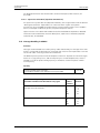
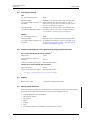
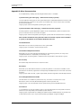
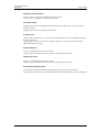
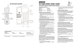
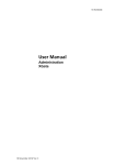
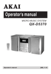
TD 91931EN
System Description
Ascom 9d
25 February 2011/ Ver. G
System Description
Ascom 9d
TD 91931EN
Contents
1 Introduction....................................................................................................................... 2
1.1 Abbreviations and Glossary ...................................................................................................... 2
2 Building Blocks .................................................................................................................. 4
2.1 Building Blocks Connections ..................................................................................................... 7
3 Telephony Functions......................................................................................................... 8
3.1 Analogue Individual Lines ......................................................................................................... 8
3.2 CAS+ Individual Lines ...............................................................................................................10
3.3 QSIG/DPNSS Interface ..............................................................................................................11
3.4 CCS Interface ...............................................................................................................................12
4 Messaging Functions, IMS .............................................................................................. 14
4.1 Integrated Message Server (IMS) ........................................................................................14
4.1.1 Supported Messaging and Alarm Functions ............................................................15
4.2 Basic Messaging .........................................................................................................................15
4.3 Customized Groups ...................................................................................................................15
4.4 Messages with Manual Acknowledge Request ..................................................................15
4.5 Messages with Delivery Receipt Request ............................................................................16
4.6 SMS (Short Message Service) .................................................................................................16
4.7 Interactive Messaging ..............................................................................................................16
4.8 Broadcast Messaging ...............................................................................................................16
4.9 Multicast Messaging .................................................................................................................16
4.10 Absence Handling ...................................................................................................................16
4.11 Data from Handset .................................................................................................................17
4.12 DECT Phonebook Service .......................................................................................................17
4.13 Alarm from Handset ..............................................................................................................17
4.13.1 Alarm with data ............................................................................................................17
4.13.2 Alarm with Base Station Location ............................................................................18
4.13.3 DECT Location ................................................................................................................18
4.13.4 Supervision of Handset (Geprüfte Sicherheit GS) ................................................18
4.14 Message Handling in IMS ......................................................................................................18
4.14.1 Priorities ..........................................................................................................................18
4.14.2 Capacity ...........................................................................................................................19
5 Messaging Functions, 9dMMS........................................................................................ 20
5.1 9d Message Mobility Server (9dMMS) .................................................................................20
5.1.1 Supported Messaging and Alarm Functions ............................................................21
5.2 Basic Messaging .........................................................................................................................21
5.3 Customized Groups ...................................................................................................................22
5.4 Messages with Manual Acknowledge Request ..................................................................22
25 February 2011/ Ver. G
System Description
Ascom 9d
TD 91931EN
5.5 Messages with Delivery Receipt Request ............................................................................22
5.6 SMS (Short Message Service) .................................................................................................22
5.7 Conference Call ...........................................................................................................................22
5.8 Absence Handling .....................................................................................................................23
5.9 Data from Handset ...................................................................................................................23
5.10 DECT Phonebook Service .......................................................................................................24
5.11 Alarm from Handset ..............................................................................................................24
5.11.1 Alarm with data ............................................................................................................24
5.11.2 Alarm with Base Station Location ............................................................................24
5.11.3 DECT Location ................................................................................................................24
5.11.4 Supervision of Handset (Geprüfte Sicherheit GS) ................................................25
5.12 Message Handling in 9dMMS ...............................................................................................25
6 System Management...................................................................................................... 26
6.1 System 900 Manager – WinBK ..............................................................................................26
6.2 Cordless System Manager (CSM) ..........................................................................................26
6.3 Remote Management ...............................................................................................................26
6.4 Clock Synchronisation ..............................................................................................................26
7 System Error Handling.................................................................................................... 27
7.1 IMS .................................................................................................................................................27
7.2 9dMMS .........................................................................................................................................27
7.3 Radio Exchange ..........................................................................................................................27
8 System Logging............................................................................................................... 28
9 Related Documents ......................................................................................................... 29
10 Document History ......................................................................................................... 31
Appendix A: System Capacity ........................................................................................... 32
A.1 Physical limitations of a DCT1800 system ......................................................................... 32
A.2 Capacity dependent on the configuration PBX – RE ........................................................ 32
A.3 Telephony ................................................................................................................................... 33
A.4 Alarm message sent from Handset...................................................................................... 33
A.5 Messaging handling ................................................................................................................. 34
A.6 Maximum simultaneous Calls, Alarm and Messaging per Base Station...................... 34
A.7 Cabling ......................................................................................................................................... 34
A.8 DECT protocol limitation .......................................................................................................... 34
Appendix B: Other Documentation................................................................................... 36
25 February 2011/ Ver. G
System Description
Ascom 9d
1
TD 91931EN
Introduction
This document gives a general description of the System 9d, a cordless DECT telephony and
messaging system for connection to private telephone exchanges.
The System 9d supports the DECT standard and is GAP compliant. The DECT technology
gives a full integration of messaging and voice functions. The DECT-system can be
integrated with System 900, as well as external applications such as different alarm
systems, networks and e-mail. This gives features such as; messages to handset, alarm from
handset, message acknowledgement, absent handling, and conference call.
1.1
Abbreviations and Glossary
9dMMS
9d Message Mobility Server:
PC based tool that enables messaging to and from the connected cordless
telephone system.
AIMS
Ascotel Information Management System
CAS
Channel Associated Signalling:
one channel is used for signalling but each user has his own speech channel.
CCS
Common Channel Signalling:
as CAS but here all speech channels are dynamically used by all users.
CLIP
Calling Line Identity Presentation.
CSM
Cordless System Manager:
PC based tool used to configure cordless telephone systems.
DECT
Digital Enhanced Cordless Telecommunications:
global standard for cordless telecommunication.
DMS
DECT Message Server:
component in the 9dMMS that handles the distribution of messages.
DPNSS
Digital Private Network Signalling System.
ELISE
Embedded LInux SErver:
hardware platform used for Unite modules
EMN
Enterprise Mobility Node:
controls and monitors circuit switched calls and provides end-users with
features like a PBX.
ESS
Enhanced System Services:
Unite module that supports advanced message routing and centralised fault
handling and logging.
GAP
Generic Access Profile:
communication protocol standard within DECT, that guarantees
compatibility of systems and components.
Hot Key
One of the ordinary number keys 0 to 9 on the cordless handset, used for
single key activation.
IMS
Integrated Message Server:
Unite module that enables messaging to and from the connected cordless
telephone system.
IP
Internet Protocol:
global standard that defines how to send data from one computer to
another through the Internet
25 February 2011/ Ver. G
2
System Description
Ascom 9d
TD 91931EN
LAN
Local Area Network:
a group of computers and associated devices that share a common
communication line.
OAP
Open Access Protocol:
XML based protocol used to create customized applications for Unite access.
PBX
Private Branch Exchange:
telephone system within an enterprise that switches calls between local
lines and allows all users to share a certain number of external lines.
QSIG
Q-signalling:
a set of standards defined by ECMA, ESTI and ISO for connection PBX to PBX
in networks.
RE
Radio Exchange:
the interface between the main PBX, the Base Stations and 9dMMS / IMS.
SMS
Short Message Service:
global protocol for sending messages between cordless telephones.
System 900 generic term for telePROTECT, teleCOURIER, and CTS 900 systems
TCP
Transport Control Protocol
Unite
generic term for messaging system that unites different systems, for
example System 900, System 9d, and teleCARE M.
WinBK
PC based tools for installation and configuration of System 900. Included in
9dMMS.
25 February 2011/ Ver. G
3
System Description
Ascom 9d
2
TD 91931EN
Building Blocks
ss
Cordle
Telephone System
Base Station
DECT Handset
RE
Main PBX
CSM
Unite System
tem 900
Sys
Unite
platform
001
9dMMS / IMS
Figure 1. Building blocks
The System 9d is a pico-cellular system that is built up by:
•
•
•
•
•
Cordless Telephone System containing; the Radio Exchange (DCT1800 / DCT1800-S),
DECT Cordless Handsets and Base Stations (BS330 / BS340 / BS370).
Management Software CSM
Either a PC with Software 9d Message Mobility Server (9dMMS) or an Integrated
Message Server (IMS), as messaging control and interface.
System 900 (On Site Paging - and Personal Security Systems) can be connected to
9dMMS or IMS. System 900 includes a Central Unit and Interface modules, for example
Alarm Module, Output Module etc.
Unite System. The Unite platform makes it possible to connect other unite modules
which enables enhanced functions and remote management of the System 9d.
The Radio Exchange is used as the interface between the main PBX, the Base Stations and
9dMMS/IMS. It can be connected to any main PBX, either by analogue lines and/or by a
digital 2 Mbit/s link. Note that the Radio Exchange DCT1800-S only supports analogue lines.
The DECT Cordless Handsets are available in a number of versions. From handsets with basic
functionality suitable in office environments to handsets suitable in environments with
needs like supervision, alarm functions and EX-classification.
The Base Station (BS330 / BS340) has in total twelve channels used for communication
with the user of a handset. One channel is reserved for broadcast and multicast messages.
25 February 2011/ Ver. G
4
System Description
Ascom 9d
TD 91931EN
1
2
3
4
5
6
7
8
9
10
11
12
014
Speech calls
Messages to/from handset
Alarm from handset
Broadcast / Multicast
Alarm from handset can occupy eleven channels, messages to/from handsets can occupy
ten channels but only eight speech calls can be handled simultaneously, see figure 2 below.
Figure 2. Channel distribution in the base Station
This means that even if a Base Station reports that it is busy i.e. fully occupied with voice
calls and/or messaging, there are always channels free for alarm from handset and
multicast/broadcast messages.
Note: To be able to use the reserved alarm channel a 9d24 Protector version is required.
The Wireless Relay Station (BS370) has five channels that handle speech calls, alarm and
messaging. One channel is reserved for broadcast and multicast messages but it does not
have any reserved alarm channel.
Both the Message Server IMS and the software 9dMMS can act as interface between the
Radio Exchange and System 900 and be used for control of the messaging functions, for
example, paging and alarm.
The IMS works on the Unite platform which enables enhanced functions such as; centralised
system supervision, system management, remote connection, fault handling, message
routing, centralised logging, broadcast and multicast messaging. The IMS can also be set to
control the communication on the system bus in System 900, i.e. in a small system the
Central Unit can be excluded. Using 9dMMS always requires a Central Unit in System 900.
The Central Unit is connected to other modules in System 900 such as Alarm Module, Output
Module, PBX Interface, Serial Interface, and Alarm Interface. These interface modules make it
possible to send predefined text messages to the cordless handsets, receive messages from
cordless handsets and transform the messages to further actions.
Software CSM is required for the RE management.
Note: 1) A Central Unit is always required if messages are to be sent on the system bus
in System 900.
Note: 2) 9dMMS is required for Conference Call in System 9d.
For detailed description of the building blocks, see:
•
•
•
•
•
Technical Product Manual DCT1800-GAP for the Radio Exchange DCT1800, Base Stations,
CSM software and the concept of DECT.
Installation and Maintenance Guide DCT1800-S and User´s Guide DCT1800-S, for Radio
Exchange DCT1800-S.
User manuals for respective DECT Cordless Handset.
System Description, On Site Paging System, TD 91024GB
System Description, Personal Security System, TD 90677GB
25 February 2011/ Ver. G
5
System Description
Ascom 9d
•
2.1
TD 91931EN
System Description, Unite, TD 92243GB
Building Blocks Connections
s Telephone System
Cordles
Air interface
DECT-GAP with SMS
Base Station
Connection between
Radio Exchange and Basestation
RE
Main PBX
PC port
PR port
Com port
CSM
Serial V.24 (RS232) connections
Unite System
Com port
System bus
System 900
Communication via LAN
Local Area network
(LAN)
Unite
moduls
IMS
PC port
PR port
Serial V.24 (RS232) connections
System 900
PC-line
Com.
port
9dMMS
Parallel port
Com port
CSM
Licence Dongle
Note: 9dMMS and CSM can run on the same PC
003
Com port
Figure 3. Blocks connections
25 February 2011/ Ver. G
6
System Description
Ascom 9d
TD 91931EN
For detailed information of which interfaces the Radio Exchange supports see, Technical
Product Manual DCT1800-GAP
3
Telephony Functions
The voice handling in the system differs depending on the configuration between the main
PBX and the Radio Exchange.
The connection between the Radio Exchange and the main PBX can be configured in the
following ways:
•
•
•
•
3.1
Analogue individual lines
CAS individual lines
QSIG (or DPNSS) Interface
CCS Interface
Analogue Individual Lines
Configuration
Air Interface
(DECT / GAP / SMS)
Base Station
7300
7301
RE
(DCT1800 /
DCT1800-S)
7302
DECT Handset
7300
7301
7302
Main PBX
Analogue extensions
IMS / 9dMMS
004
CSM
Figure 4. Every analogue line is dedicated to a specific Cordless Handset.
In this configuration all users have their own analogue extension in the main PBX. Both the
DCT1800, and the DCT1800-S can be used.
Function
All PBX functions that are tied to the extension, for example call back, call transfer, call
diversion, etc. can be used by the cordless handset.
When all users have their own private analogue extension in the main PBX every line is
dedicated to a specific cordless handset. If the user has a desk telephone connected to the
same line, the cordless handset will work in parallel with this one. That means that at an
incoming call the desk telephone and the cordless handset will ring at the same time. If the
25 February 2011/ Ver. G
7
System Description
Ascom 9d
TD 91931EN
user instead has a digital desk telephone, the calls must be diverted to the analogue line,
directly or after a pre-set period.
Calls from one handset to another are always switched in the main PBX.
CLIP
If the number of the calling party is supported by the PBX this is not presented in the display
on the cordless handset when using analogue lines.
If the PBX is equipped with software for paging, this can however be done with a PBX
interface module in system 900. To use the function, incoming calls must be diverted to the
PBX interface module. An incoming call is then placed on hold for “meet-me answer” and
data is sent to the cordless handset via system 900. When answering (at hook-off), the
cordless handsets automatically dials the call-pickup code for “meet-me answer” which
establishes the connection. A disadvantage is that if someone else is calling he/she do not
get a busy indication, since the call is diverted to the PBX interface module.
The cordless handsets also support different ring signals to indicate internal and external
calls.
Limitations
DCT1800
•
•
•
•
Analogue individual lines, max. 224 (28 boards)
Simultaneous calls, max. 60
Base Stations, max. 200 (25 boards)
Cordless Handsets, max. 224
Note that the DCT1800 can contain max. 36 boards including the CPU board (Central
Processing Unit) which in reality gives the limitations shown in table.
Analogue lines
Base Stations
Cordless
Handsets
224 (max)
56
224
80
200 (max)
80
DCT1800-S
•
•
•
•
Analogue individual lines, max. 40
Simultaneous calls, max. 16
Base Stations, max. 8
Cordless Handsets, max. 40
25 February 2011/ Ver. G
8
System Description
Ascom 9d
3.2
TD 91931EN
CAS+ Individual Lines
Configuration
Air Interface
(DECT / GAP / SMS)
Base Station
RE
(DCT1800)
MD110/
Meridian 1/
Succession
1000M
7300
7301
7302
7300
00
73
7301
7302
7302
CAS extensions
CSM
IMS / 9dMM
005
DECT Handset
Figure 5. Each Cordless Handset is assigned to a fixed channel in the CAS+ tie line.
If the main PBX is a MD110 with software BC6.3 or higher, Meridian 1, or Succession 1000M,
it supports CAS protocol and can be connected directly to the DCT1800 via the CAS+
interface. Each digital (2 Mbit/s) CAS+ interface has 30 fixed channels to which 30 cordless
handsets can be assigned.
Note that each board in DCT1800 supports two CAS+ interfaces while each board in MD110
only supports one CAS+ interface.
Function
All PBX functions associated with an analogue extension, for example call back, call transfer,
call diversion, etc. can be used by the cordless handset.
All cordless handsets have their own fixed channels in the CAS+ tie line. If also a fixed
telephone is used all calls must be diverted from this to the cordless handset, directly or
after a pre-set period. At an incoming call, the main PBX connects the fixed channel in the
CAS interface to the Radio Exchange. The Radio Exchange sets up the connection between
the cordless handset and the fixed channel via the Base Station. Calls from one cordless
handset to another are switched by the main PBX.
CLIP
If the number of the calling party is supported by the PBX this is presented in the display.
The cordless handsets also support different ring signals to indicate internal and external
calls.
See Function Description, PBXs supporting CAS+ Interface in System 9d, TD 92291GB for
more information.
Limitations
•
•
•
CAS+ extensions, 600 channels (10 boards)
Simultaneous calls, max. 60.
Base Stations, max. 200 (25 boards)
25 February 2011/ Ver. G
9
System Description
Ascom 9d
•
3.3
TD 91931EN
Maximum 300 Cordless Handsets recommended, up to 600 Cordless Handsets is possible
(traffic dependent)
QSIG/DPNSS Interface
Configuration
Air Interface
(DECT / GAP / SMS)
Base Station
RE
(DCT1800)
7300
7302
7300
Concentrator
Main PBX
QSIG/DPNSS
7300
00
73
7301
7302
7302
7302
CAS individual
lines
CSM
DECT Handset
006
IMS / 9dMMS
Figure 6. The Cordless Handsets share the resources in the QSIG/DPNSS interface but
have their own speech channel in the CAS interface.
The concentrator connects to the main PBX via a digital 2 Mbit/s QSIG (or DPNSS) interface,
and to the DCT1800 via a CAS interface. All cordless handsets are sharing the channels in
the QSIG/DPNSS link, but have their own fixed channels in the CAS interfaces. The 2 Mbit/s
QSIG/DPNSS interface provides 30 shared extensions and every CAS interface has 30 fixed
channels to which 30 cordless handsets are assigned.
Function
At an incoming call, the PBX selects a free QSIG/DPNSS channel to the concentrator. The
concentrator connects the call to the Radio Exchange, via the fixed channel in the CAS
interface. The Radio Exchange sets up the connection between the cordless handset and the
fixed channel, via the Base Station. The concentrator in turn connects the fixed channel and
the QSIG/DPNSS channel.
Calls from one cordless handset to another are switched by the concentrator and do not load
the QSIG/DPNSS link.
CLIP
If the number of the calling party is supported by the PBX this is presented in the display.
The cordless handsets also support different ring signals to indicate internal and external
calls.
Note that all PBX functions, for example call back at busy, calling name identification and
presentation to attendant, may not be available over the QSIG/DPNSS link. This is vendor
dependent.
25 February 2011/ Ver. G
10
System Description
Ascom 9d
TD 91931EN
Limitations
•
•
•
•
•
3.4
QSIG/DPNSS, 60 channels (1 board) limited by max. simultaneous calls
CAS individual lines, 600 lines (10 boards)
Simultaneous calls, max. 60
Base Stations, max. 200 (25 boards)
Maximum 300 Cordless Handsets recommended, up to 600 Cordless Handsets is possible
(traffic dependent)
CCS Interface
Configuration
Base Station
7300
7300
7302
Ascotel or EADS
CSM
730
0
AIMS
7300
7302
RE
2
7301
730
Ascotel
2065
Main PBX
QSIG
CCS
7302
Voice mail
007
DECT Handset
Figure 7. The Cordless Handsets share the resources in a QSIG/CCS configuration.
If the main PBX is an Ascotel I5 (or higher) AMI or an EADS Telecom PBX (M6501/M6540 IP
or NeXspan L/S/C/50) it can be connected directly to the Radio Exchange via the 2 Mbit/s
CCS interface. However, all PBX suppliers do not support the CCS interface and in that case
the Radio Exchange can connect indirectly to the main PBX with an Ascotel or an EADS PBX.
All handsets share the same channels to and from the Radio Exchange and it is enough with
only one DTU board (i.e. 60 channels) in the Radio Exchange to cover all users (<600) in the
cordless telephone system.
In figure 7 an Ascotel 2065 with Ascotel Mobility Interface (AMI) software is used as a QSIG
converter to the main PBX. The Ascotel then serves as the PBX for the cordless handsets i.e.
the Ascotel provides the switching of the calls and the level of functionality to and from the
handsets. The level of QSIG functionality depends on a combination of what is implemented
in the main PBX and the Ascotel.
The Radio Exchange uses a Common Channel Signalling (a common name for this protocol is
also “S2”) path towards the Ascotel/EADS. The S2-protocol is standardised by ETSI and
some suppliers uses it to connect to extensions on a Primary Rate interface for example to
external voice mail systems. The S2-signalling between the Ascotel/EADS and the Radio
Exchange has been improved to also bring user information such as the Display
management and Message Waiting Indication (MWI) to the cordless handsets.
25 February 2011/ Ver. G
11
System Description
Ascom 9d
TD 91931EN
Function and Limitations
Ascotel/EADS supports a high level of functionality, such as; displaying the calling parties
name and number, call waiting, call routed to attendant or voice mail in case of no reply, call
forwarding, possibilities of having simultaneous, sequential and other types of ringing to a
group of subscribers etc.
For more information see:
Function Description, Ascotel Mobility Interface (AMI), TD 92158GB and
Function Description, PBXs supporting CCS Interface in system 9d, TD 92292GB.
25 February 2011/ Ver. G
12
System Description
Ascom 9d
4
TD 91931EN
Messaging Functions, IMS
4.1
Integrated Message Server (IMS)
Network Time Protocol
Open Access Protocol
IMS Messaging Tool
IMS phonebook
Basic Alarm Manager
System 900
System bus
Com. port
Radio Exchange
System 900 Interface
010
Group Handler DECT Interface
The Integrated Message Server (IMS) works as an interface between the Radio Exchange
and System 900. It contains support for messaging and alarm in the System 9d and includes
basic versions of customer tools such as a web based Messaging Tool and Basic Alarm
Manager (BAM).
The IMS is based on the ELISE hardware and works on the IP based Unite system platform.
The Unite platform makes it possible to connect other Unite modules which enables
enhanced system functions, see System Description, Unite, TD 92243GB.
The Network Time Protocol (NTP) makes it possible to synchronize the time in the whole
system.
The IMS works as an OAP Server which enables exchange of data between systems and
makes messaging from customized applications possible, see Function Description, Open
Access Protocol (OAP), TD 92215GB.
System 900 Interface connects directly to the system bus in System 900 and can control
the communication on the bus. If no messages are sent on the system bus the central unit in
system 900 can be excluded.
DECT Interface is connected via a serial connection to the Radio Exchange in the cordless
telephone system.
Group Handler enables 30 groups with up to 15 users in each group and 1 group with up to
50 users.
IMS Phonebook contains 500 entries and is included in the IMS.
For a detailed description of the IMS see Installation and Operation Manual, IMS - Integrated
Message Server, TD 92161GB.
25 February 2011/ Ver. G
13
System Description
Ascom 9d
4.1.1
TD 91931EN
Supported Messaging and Alarm Functions
•
Every IMS has a licence from start, supporting:
- basic one-way messaging
- messages with delivery receipt (automatic acknowledge)
- messages with manual acknowledge
- interactive messaging
- erase of sent messages
- user data from handsets
- Short Messaging Service (SMS) between handsets
- Personal alarm with location information from handsets.
•
Following functions are achieved (dependent on licence) by adding an ESS module:
- Broadcast Messaging
- Multicast Messaging
- Remote Management
- System Survey
- Fault Logging
For more information see, Data Sheet, Enhanced System Service (ESS), TD 92250GB.
4.2
Basic Messaging
A message to a cordless handset can be generated either from the message tool in the IMS,
contact inputs directly on the IMS, or SMS between the handsets. Via the system bus it is
also possible to send text messages from the System 900 to cordless handsets. The
message can be initiated by, for example closing (or opening) a contact.
If the system includes NetPage software, text messages can be sent from any PC with a web
browser in your network. A customized PC applications can also, via an Open Access Server
(OAS), communicate with the System 9d.
Cordless handsets supporting messaging functions is required. Messaging functions in
cordless handset are described in respective User Manual, see “Related Documents” on
page 28.
4.3
Customized Groups
IMS has an integrated Group Handler enabling the creation of 30 groups with up to 15 users
in each group, and 1 group with up to 50 users. By adding an ESS to the system larger and
more groups with enhanced functions are enabled.
4.4
Messages with Manual Acknowledge Request
Messages with a manual acknowledge request must be acknowledged by the user of the
cordless handset. A message with a manual acknowledge request can be sent from the
Alarm Module, a Serial Interface connected to external equipment, or the Control Keyboard
in System 900. It can also be sent from the IMS (BAM), NetPage, or a customized application
via the OAS, in the Unite System.
If the module or external equipment sending the message does not receive the manual
acknowledge, it can send the message to other cordless handsets or take other actions.
25 February 2011/ Ver. G
14
System Description
Ascom 9d
4.5
TD 91931EN
Messages with Delivery Receipt Request
When a message with a delivery receipt request is sent to a handset, the handset
automatically sends an acknowledge when the message is received. Messages with a
delivery receipt request can be sent from an Alarm Module, a Serial Interface connected to
external equipment, or the Control Keyboard in System 900. It can also be sent from the IMS
(BAM), NetPage, or a customized application via the OAS, in the Unite System.
4.6
SMS (Short Message Service)
SMS can be sent between handsets within the system, and it is also possible to send an SMS
to a pre-defined destination address. For more information see the User Manual for
respective Cordless Handset.
4.7
Interactive Messaging
Interactive messaging makes it possible for a client application to have a two-way
communication in plain language with a user of a cordless handset.
For more information see Function Description, Interactive Messaging (IM), TD 92168GB.
4.8
Broadcast Messaging
With Broadcast messaging it is possible to deliver one message to all users in the system
simultaneously. When a message is sent as a broadcast all handsets in the coverage area
can receive the message. The system does not get a delivery receipt from the handsets, but
the message is sent three times to increase the reliability of the transmission.
An ESS with basic licence and cordless handsets 9d24 Messenger or Protector versions are
required.
4.9
Multicast Messaging
Multicast messaging makes it possible to create and reach large groups in the system. A
multicast message is sent out simultaneously to all members in the group. All handsets in
the coverage area can receive the message. The system does not get a delivery receipt from
the handsets, but the message is sent three times to increase the reliability of the
transmission.
An ESS with basic licence and cordless handsets 9d24 Messenger or Protector versions are
required.
4.10 Absence Handling
Three different types of absence are supported by the system; Automatic-, Manual- and
Late absence. When absent, messages can be diverted to another cordless handset or to a
pager in the System 900.
Automatic Absence is an option that can be set in the cordless handset. Information is then
sent to an ESS, or to the Central Unit in System 900, when the cordless handset is placed in
or removed from the charger.
Manual Absence is a function programmable in the handset as a “Hot Key”. Absent on/off
can be selected and sent to an ESS or to the Central in System 900.
25 February 2011/ Ver. G
15
System Description
Ascom 9d
TD 91931EN
Late Absence is a function that is used when the cordless handset can not be reached, for
example when it is out of coverage
For more information see Function Description, Number Planning and Message Routing in
Unite, TD 92554GB and Function Description, Absence Indication, TD 92101GB.
4.11 Data from Handset
It is possible to send user data from the cordless handset as “Data Send”. This data is
defined by the user and is transmitted by pressing a hot key on the handset. The data is
sent to System 900 or the Unite System for distribution to interface modules, for example
the Alarm Module, the Output Module, the AMS, or via the OAS to a customized application.
User data can for example be used for opening/closing a door by activating an output
connected to a relay on the Output Module, or activate the Alarm Module to send a preprogrammed text message to other cordless handsets.
For more information see, Function Description, Applications based on Sending Data from
handset, TD 92095GB.
4.12 DECT Phonebook Service
DECT Phonebook Service is delivered together with the IMS. The function enables access to a
centralized telephone number directory from the cordless handset. The telephone directory
may be located in the site database or in any MSSQL-compliant database.
DECT Phonebook Service has the same function as the IMS Phonebook. The difference is that
the DECT Phonebook service has support for a database that contains more entries. IMS
Phonebook and DECT Phonebook service can be used at the same time as long as they have
separate addresses.
4.13 Alarm from Handset
Alarm messaging includes all types of alarm from handsets, location etc. Cordless handsets
equipped with alarm functions can send different types of alarm messages to the System
900 or the Unite System. The data can be sent to interface modules, for example an Alarm
Module or Output Module. The Alarm Module is used to generate group messages to other
cordless handsets while the Output Module activates outputs connected to signal lamps or
sirens.
Alarm messages can also be sent to an Alarm Manager Server (AMS) for further actions. The
AMS can for example activate an output connected to a signal lamp or siren, or present the
alarm on a PC with equipped with the AMC software (an Alarm Management Client). The PC
can besides the identity, alarm type and time also display the location graphically.
For more information see the document: Function Description, Alarm from Handsets TD
92099GB.
4.13.1 Alarm with data
Additional data for, example a location code, can be sent along with an alarm. The data and
type of alarm can be presented on an Alarm Management Client, but it can also be indicated
by an Alarm- or Output Module.
For detailed information see the document: Function Description, Alarm from Handsets TD
92099GB.
25 February 2011/ Ver. G
16
System Description
Ascom 9d
TD 91931EN
4.13.2 Alarm with Base Station Location
An approximate location of the cordless handset is possible to add to an alarm sent from the
handset. The handset evaluates at alarms the field strength ratio of the individual radio
Base Stations and sends the best-rated Base Station as a location of where the alarm was
activated. However, positioning based on radio field strength measurements must be
regarded as an indication only.
The type of alarm and the location of the handset can be presented on an Alarm
Management Client (AMC). The AMC client can besides the identity, alarm type and time also
display the location graphically. The alarm can also be indicated by an Alarm- or Output
Module.
For detailed information see the document: Function Description, Alarm from Handsets TD
92099GB.
4.13.3 DECT Location
With DECT Location it is possible to send an alarm with the two latest location codes. This
makes it possible to decide in which part of a building a person is located, and in which
direction he is moving. It does not give an exact location from where an alarm is transmitted
but, depending on how many location devices 9dLDs that are used, a high precision of the
location can be achieved.
For detailed information see the document: Function Description, DECT Location, TD
92177GB.
4.13.4 Supervision of Handset (Geprüfte Sicherheit GS)
An option in the System 9d is GS (Geprüfte Sicherheit), that is approved to fulfil the German
“Berufsgenossenschaft” requirements for a Personal Alarm System with speech
transmission. GS is intended for people working in environments where a risk of accident
exists, for example at industries, prisons, hospitals and power stations.
Special versions of the cordless handset and software PCPRO are required. For detailed
information see the document: Function Description, Supervision of Handsets (Geprüfte
Sicherheit GS), TD 92091GB.
4.14 Message Handling in IMS
4.14.1 Priorities
Messages are distributed first-hand in priority order and secondly, for messages with same
priority, in time order. If distribution of a message fails it returns to the queue but is now the
last in time order. A message can be sent three times.
The different priority levels have reserved places of the max. 10 places for active messages.
Alarm has 2, high priority has 3, and normal priority has 5 reserved places. But, Alarm is
allowed to use all ten places and high priority is allowed to use the five places used for
normal priority.
25 February 2011/ Ver. G
17
System Description
Ascom 9d
TD 91931EN
4.14.2 Capacity
Alarm messages from Cordless Handset
Time until received in System 900:
~ 2.5 sec
Incoming messages to Cordless Handset 9d24 (version 3.0 or later)
The time for a message to be delivered differ dependent on how many characters the
message contain and if it is delivered to a single handset or a group of handsets.
Number of message characters:
No of
Cordless
Handsets:
Time in seconds until
one handset is paged:
20 characters
1
~ 4
120 characters
1
~ 5
240 characters
1
~ 6
500 characters
1
~ 9
Number of message characters:
No of
Cordless
Handsets:
Time in seconds until
all handsets are
paged:
20 characters
1
10
30
100
~ 4
~ 6
~ 14
~ 43
120 characters
1
10
30
100
~ 5
~ 7
~ 17
~ 56
Incoming messages to Cordless Handsets in a broadcast / multicast group
Number of message characters
No of
Cordless
Handsets:
Time in seconds until
the group is paged:
20 characters
Unlimited
~ 4
120 characters
Unlimited
~ 4
240 characters
Unlimited
~ 7
500 characters
Unlimited
~ 14
25 February 2011/ Ver. G
18
System Description
Ascom 9d
5
TD 91931EN
Messaging Functions, 9dMMS
Message
Base Station
RE
Main PBX
DECT Handset
Browser
9dMMS
Messaging via LAN
Browser
System 900
PC-
line
Local Area Network
(LAN)
008
System-bus
Figure 8. Messages can be sent both from System 900 and a PC with web browser.
5.1
9d Message Mobility Server (9dMMS)
WinBK
PU-models
PCPAR
System 900
PC-line
Com.
port
Site Database
Manager (DBServer)
Dect Message
Server (DMS)
Communications
Server (CSvr32)
License
Administrator
WebPage
Parallel
port
License Dongle
009
Messaging via LAN
Radio Exchange
Com. port
The software package 9dMMS controls the messaging functions (for example, paging and
alarm). It is also the link between the RE and the Central Unit in System 900. 9dMMS is
installed on a PC using Windows NT as platform. The PC is connected to the Central Unit and
to the RE. 9dMMS supports message handling, message acknowledgement, alarm and
absent handling. 10 messages can be active at the same time but the message queue can
hold up to 200 messages.
25 February 2011/ Ver. G
19
System Description
Ascom 9d
TD 91931EN
9dMMS supplies the software tools for managing the System 9d. It consists of Win BK, Dect
Message Server (DMS), Communications Server (CSvr32) and Site Database Manager
(DBServer).
WinBK is a system management tool and includes the Pocket Unit administration software.
Dect Message Server is handling the connection to the RE and it controls the paging, alarm,
acknowledgement, and absent functions. It is using Site Database Manager to keep track on
the cordless handsets, and the Communications Server to connect to the Central Unit in the
System 900. When a message is sent it is distributed through the Communication Server to
the Dect Message Server. Dect Message Server then checks with the Site Database Manager
that the message is intended to a handset. The message is finally distributed to the Radio
Exchange and to the handset.
When a handset sends an alarm, the Dect Message Server receives the message from the
Radio Exchange and forwards it to the Communications Server.
Communications Server distributes the alarm, acknowledgement or absents message to
whatever action that has to be done; for example giving an alarm to an alarm application in
the system.
Licence Administrator is the licence tool and handles the licences for Dect Message Server,
WebPage, sending messages to cordless handsets, receiving alarm from cordless handsets,
and sending “Data Send” from cordless handsets.
If desired, the 9dMMS can coexist with the Windows-based software WebPage on the same
server (optional). This option gives you possibility to send messages via your web browsers.
5.1.1
Supported Messaging and Alarm Functions
Every 9dMMS has a basic license for 20 users from start. From there it is possible to upgrade
to 50, 100 or an unlimited number of users.
5.2
•
Basic 9dMMS licence supports basic one-way messaging
•
Basic 9dMMS licence added with Enhanced messaging supports:
- group messaging
- messages with delivery receipt (automatic acknowledge)
- messages with manual acknowledge
- user data from handsets
- conference call
- message priority handling in 9dMMS
- absent handling
•
Basic 9dMMS licence added with DECT Phonebook Service supports DECT Phonebook
Service
•
Basic 9dMMS licence added with DECT SMS supports sending SMS between handsets
within the system
•
Basic 9dMMS licence added with Alarm messaging supports alarm from handsets
(includes all types of location information)
Basic Messaging
Via the PC-line connection it is possible to send text messages from the System 900 to
cordless handsets. The message can be initiated by, for example closing (or opening) a
25 February 2011/ Ver. G
20
System Description
Ascom 9d
TD 91931EN
contact. If the system includes WebPage software, text messages can also be sent from any
PC with a web browser in your network.
Cordless handsets supporting messaging functions is required. Messaging functions in
cordless handset are described in respective User Manual. See “Related Documents” on
page 28.
5.3
Customized Groups
If a message is to be sent to a group of cordless handsets it is possible to create group
numbers in the application Site Manager in 9dMMS. 30 customized groups with up to 10
telephone numbers in each group can be created.
Basic 9dMMS license added with Enhanced messaging is required.
5.4
Messages with Manual Acknowledge Request
Messages with a manual acknowledge request must be acknowledged by the user of the
cordless handset.
Messages with a manual acknowledge request can be sent from an Alarm Module, a Serial
Interface connected to external equipment and the Control Keyboard. It can also be sent
from a PC with the software PCPRO. (The PC is connected to the system via an Alarm
Interface).
If the module or external equipment sending the message does not receive the manual
acknowledge, it can send the message to other cordless handsets or take other actions.
Basic 9dMMS license added with Enhanced messaging is required.
For detailed information see the document: Function Description, Manual
Acknowledgement, TD 92096GB
5.5
Messages with Delivery Receipt Request
When a message with a request for a delivery receipt (automatic acknowledge) is sent to a
handset, the handset automatically sends an acknowledge when the message is received.
Messages with delivery receipt can be sent from an Alarm Module, a Serial Interface
connected to external equipment and the Control Keyboard.
Basic 9dMMS license added with Enhanced messaging is required.
5.6
SMS (Short Message Service)
SMS can be sent between cordless handsets within the system, and it is also possible to
send an SMS to a pre-defined destination address. More information see respective User
Manual. See “Related Documents” on page 28.
Basic 9dMMS license added with DECT SMS handset to handset is required.
Note: PBX dependent
5.7
Conference Call
Conference call is a function that enables a group of users to have a cordless telephone
conference. A separate set of trunk lines with “hunting” in the main PBX and one Conference
25 February 2011/ Ver. G
21
System Description
Ascom 9d
TD 91931EN
Line Module (CLM) for each line is needed. The number of CLM modules determines how
many of the group members that can be connected to one conference call. If there are more
members in the group than the number of CLM modules, the last members answering get
busy signal.
Different conference groups can share CLM modules but if there is a conference call in
progress, members in the second group get the next free lines and will overhear the first call,
or get busy signal if all lines are occupied. To ensure overhearing and occupied lines it is
recommended that every conference group have their own set of tie lines and CLM modules.
A conference call can be started at special events from, for example an Alarm Module
triggered by a machine alarm. The module sends a message to a group of cordless handsets
and 9dMMS adds the dial code to the tie lines when it indicates the group number as a
conference call number. The message received in the cordless handset consists of the text
message and the dial code. When the hook is pressed the dial code is dialled from the
handset and the call is connected to the first free CLM module. Every handset connected to a
CLM module will be connected in a group via a speech bus on the CLM modules. A conference
call may also include Control Keyboards, PBX Interface modules, and U922 transceivers if the
speech bus on the CLM modules is connected to the speech bus in the System 900.
Basic 9dMMS license added with Enhanced messaging is required.
For more information see the document: Function Description, Conference Call, TD 92100GB.
5.8
Absence Handling
Three different types of absence are supported by the system; Automatic-, Manual- and
Late absence. When absent, messages can be diverted to another cordless handset or to a
pager in the System 900.
Automatic Absence is an option in the cordless handset. When enabled, set/reset “absence”
is sent to the Central Unit when the cordless handset is placed in or removed from the
charger.
Manual Absence is a function programmable in the handset as a “Hot Key”. Absent on/off
can be selected and sent to the Central Unit.
Late Absence is a function that is used when the cordless handset can not be reached, for
example when it is out of coverage
Basic 9dMMS license added with Enhanced messaging is required.
For detailed information see the document: Function Description, Absence Indication, TD
92101GB.
5.9
Data from Handset
It is possible to send data from the handset as “Data Send”. This data is defined by the user,
and is transmitted by pressing a hot key on the handset. The data is sent to the System 900
and is then distributed to interface modules, for example an Alarm Module or Output
Module. User data can for example be used for opening/closing a door by activating an
output on the Output Module connected to a relay. It can also activate the Alarm Module to
send a pre-programmed text message to other cordless handsets.
Basic 9dMMS licence added with Enhanced messaging is required.
For detailed information see the document: Function Description, Applications based on
Sending Data from handset, TD 92095GB.
25 February 2011/ Ver. G
22
System Description
Ascom 9d
TD 91931EN
5.10 DECT Phonebook Service
The function enables access to a centralized telephone number directory from the cordless
handset. Depending the DECT Phonebook Service license (Basic or Professional) the
telephone directory may be located in the site database or in any MSSQL-compliant
database.
Basic 9dMMS license added with DECT Phonebook Service is required.
5.11 Alarm from Handset
Alarm messaging includes all types of alarm from handsets, location etc.
Cordless handsets equipped with alarm functions can send different types of alarm
messages to the System 900. The alarm message is then distributed to interface modules,
for example an Alarm Module or Output Module for further actions. The Alarm Module is
used to generate group messages to other cordless handsets while the Output Module
activates outputs connected to signal lamps or sirens.
Alarm messages can also, via an Alarm Interface be presented on a PC with the software
PCPRO. The PC can besides the identity, alarm type and time also display the location
graphically.
Basic 9dMMS license added with Alarm messaging is required.
For detailed information see the document: Function Description, Alarm from Handsets TD
92099GB
5.11.1 Alarm with data
Additional data for, example a location code, can be sent along with an alarm. The data and
type of alarm can be displayed on a PC with the software PCPRO, but it can also be indicated
by an Alarm- or Output Module.
For detailed information see the document: Function Description, Alarm from Handsets TD
92099GB
5.11.2 Alarm with Base Station Location
An approximate location of the cordless handset is possible to add to an alarm sent from the
handset. The handset evaluates at alarms the field strength ratio of the individual radio
Base Stations and sends the best-rated Base Station as a location of where the alarm was
activated. However, positioning based on radio field strength measurements must be
regarded as an indication only.
The type of alarm and the location of the cordless handset can be displayed on a PC with the
software PCPRO. The PC can besides the identity, alarm type and time also display the
location graphically. The alarm can also be indicated by an Alarm- or Output Module.
For detailed information see the document: Function Description, Alarm from Handsets TD
92099GB
5.11.3 DECT Location
With DECT Location it is possible to send an alarm with the two latest location codes. This
makes it possible to decide in which part of a building a person is located, and in which
direction he is moving. It does not give an exact location from where an alarm is transmitted
but, depending on how many location devices 9dLDs that are used, a high precision of the
location can be achieved.
25 February 2011/ Ver. G
23
System Description
Ascom 9d
TD 91931EN
For detailed information see the document: Function Description, DECT Location, TD
92177GB
5.11.4 Supervision of Handset (Geprüfte Sicherheit GS)
An option in the System 9d is GS (Geprüfte Sicherheit), that is approved to fulfil the German
“Berufsgenossenschaft” requirements for a Personal Alarm System with speech
transmission. GS is intended for people working in environments where a risk of accident
exists, for example at industries, prisons, hospitals and power stations.
Special versions of the 9d23 MkII Handset and software PCPRO are required. For detailed
information see the document: Function Description, Supervision of Handsets (Geprüfte
Sicherheit GS), TD 92091GB
5.12 Message Handling in 9dMMS
Priorities
Messages are distributed first-hand in priority order and secondly, for messages with same
priority, in time order. If distribution of a message fails it returns to the queue but is now the
last in time order. A message can be sent three times.
The different priority levels have reserved places of the max. 10 places for active messages.
Alarm has 2, high priority has 3, and normal priority has 5 reserved places. But, Alarm is
allowed to use all ten places and high priority is allowed to use the five places used for
normal priority.
Capacity
Time for sending Alarm messages
from Cordless Handset until received in the System 900:
~ 2.5 sec
Time for incoming messages
to Cordless Handset until all handsets are paged
No of
Cordless
Handsets:
Time in
seconds:
Messages with 20 characters:
1
10
30
100
~ 4
~ 6
~ 14
~ 43
Messages with 120 characters:
1
10
30
100
~ 5
~ 7
~ 17
~ 56
25 February 2011/ Ver. G
24
System Description
Ascom 9d
6
TD 91931EN
System Management
6.1
System 900 Manager – WinBK
The software package WinBK is the system management tool and used for configuration
and administration of System 900. WinBK is included in the software package 9dMMS and is
operating in the same PC.
For detailed description of WinBK see: User Guide WinBK 5.0, TD 91592GB.
6.2
Cordless System Manager (CSM)
RE
Base Stations
Main PBX
9dMMS / IMS
Radio Exchange
Management System
011
CSM
Figure 9. Management system for the Radio Exchange
The software CSM is required for cordless telephone system initialization, system
maintenance and updating, system trouble shooting and repair. It can be operating in the
same PC as 9dMMS.
For more information see: Technical Product Manual DCT1800-GAP.
6.3
Remote Management
Remote management of System 9d is enabled by connecting an ESS module on the Unite
platform. The CSM software and WinBK can be operating on the same PC.
For more information see:Function Description, Remote Management, TD 92257GB.
6.4
Clock Synchronisation
It is possible to synchronize the clocks in the whole system by a setting in the IMS. See,
Installation Guide ELISE2, TD 92232GB.
25 February 2011/ Ver. G
25
System Description
Ascom 9d
7
TD 91931EN
System Error Handling
7.1
IMS
The IMS has a function indicator that visibly indicates different status of the module. It also
has an error relay which releases when IMS has lost communication with a system, shut
down, restarted etc. The error relay can be connected to a siren or a signal lamp.
In a system with many components and interfaces, there is a need to be able to survey and
supervise the whole system, not only the modules and components themselves. This
centralised system survey and supervision is solved by using the Enhanced System Services
(ESS).
For more information see Function Description, System supervision and Fault Handling in
Unite, TD 92252GB.
7.2
9dMMS
To ensure the safety of the message handling, the connections from 9dMMS to the Radio
Exchange and to the Central Unit are both supervised. Dect Message Server in 9dMMS is
taking care of the connection to the Radio Exchange and sends a status report to the Central
Unit in case of error, while the PC-line connection is supervised by the Central Unit. In both
cases, the errors are indicated by the Central Unit.
To notify an error the Central Unit can be programmed to activate the system relay or to
initiate a paging to a pager in System 900 with a predefined display message. The system
relay can be connected to a siren or a signal lamp. When the connection is working again a
“System OK” message can be sent to a cordless handset.
7.3
Radio Exchange
The Radio Exchange DCT1800 has an error relay that can be used for notification of faults. If
connected to an input on an Alarm Module a predefined text message informing that an
error has occurred, can be sent to a cordless handset.
More detailed error reports can be sent from the Radio Exchange, via the IMS, to an ESS. The
error reports can be both persistent and non-persistent errors, persistent means that the
error is reported as active until it has been taken care of, either manually or automatically by
the reporting system.
Example:
•
Non-persistent errors:
- System restarts
- Communication errors
•
Persistent errors:
- Board errors
- CPU (Central Processing Unit) errors
- Base Station errors
If the communication should fail between the Radio Exchange and the IMS, the Radio
Exchange will notify the CSM and the IMS will notify the ESS.
For more information see System Description, Unite, TD 92243GB.
25 February 2011/ Ver. G
26
System Description
Ascom 9d
8
TD 91931EN
System Logging
System logging is activated from the CSM. The CSM generates one log file every 24 hour and
sends it to a specified directory. The logfile can then be analyzed with an excel tool, the
Cordless System Analyser.
The analyze shows the total number of calls, dropped calls, call lists, number of calls on every
base station, system load, handovers, etc.
25 February 2011/ Ver. G
27
System Description
Ascom 9d
9
TD 91931EN
Related Documents
Technical Product Manual DCT1800-GAP
TD92093GB
Installation and Maintenance Guide DCT1800-S
User´s Guide DCT1800-S
System Description, On Site Paging System
TD 91024GB
System Description, Personal Security System
TD 90677GB
System Description, Unite
TD 92243GB
User Guide WinBK 5.0
TD 91592GB
User Guide 9d23
M0225130
User guide 9d23 MkII
M0262101
Quick Reference Guide 9d24
M0263330
Quick Reference Guide OfficeM
M0269601
User Manual 9d23
TD 91815GB
User Manual 9d23 MkII
TD 92089GB
User Manual 9d24
TD 92136GB
User Manual OfficeM
TD 92288GB
Data Sheet, 9dMMS
TD 91720GB
Data sheet, Integrated Message server (IMS)
TD 92160GB
Data Sheet, Enhanced System Service (ESS)
TD 92250GB
Data Sheet, Central Unit T942C
TD 91681GB
Data Sheet, Output module T941OM
TD 90864GB
Data Sheet, Alarm Modules T941AM8/AM32
TD 90862GB
Data Sheet, Alarm Interface P940AI
TD 90630GB
Data Sheet, PBX Interface T942PX
TD 91032GB
Data Sheet, Control Keyboard H900C, H900T, T900R
TD 90350GB
Data Sheet, AMS Alarm Management Server
TD 92144GB
Installation Guide ELISE2
TD 92232GB
Installation and Operation Manual, 9d Message Mobility Server
TD 91835GB
Installation and Operation Manual, WebPage 1.3
TD 91740GB
Installation and Operation Manual, IMS - Integrated Message Server
TD 92161GB
Installation and Operation Manual, AMS Alarm Management Server
TD 92047GB
Installation and Operation Manual, Alarm Management Client
TD 92145Gb
Installation and Operation Manual, Enhanced System Service (ESS)
TD 92253GB
Function Description, Ascotel Mobility Interface (AMI)
TD 92158GB
Function Description, PBXs supporting CAS+ Interface in System 9d
TD 92291GB
Function Description, PBXs supporting CCS Interface in system 9d
TD 92292GB
Function Description, Interactive Messaging (IM)
TD 92168GB
Function Description, System supervision and Fault Handling in Unite
TD 92252GB
Function Description, Number Planning and Message Routing in Unite
TD 92554GB
Function Description, Remote Management
TD 92257GB
Function Description, Open Access Protocol (OAP)
TD 92215GB
25 February 2011/ Ver. G
28
System Description
Ascom 9d
TD 91931EN
Function Description, Supervision of Handsets (Geprüfte Sicherheit GS)
TD 92091GB
Function Description, Applications based on Sending Data from handset
TD 92095GB
Function Description, Manual Acknowledgement
TD 92096GB
Function Description, Alarm from Handsets
TD 92099GB
Function Description, Conference Call
TD 92100GB
Function Description, Absence Indication
TD 92101GB
Function Description, DECT Location
TD 92177GB
25 February 2011/ Ver. G
29
System Description
Ascom 9d
10
TD 91931EN
Document History
For details in the latest version, see change bars in the document.
Version Date
Description
G
Added: A.8 DECT protocol limitation on page 33
4 February 2011
25 February 2011/ Ver. G
30
System Description
Ascom 9d
TD 91931EN
Appendix A: System Capacity
A.1
A.2
Physical limitations of a DCT1800 system
No. of cabinets per system:
4
System boards per cabinet:
9
Capacity dependent on the configuration PBX – RE
DCT1800-S System with Analogue Individual lines
Analogue individual lines:
40 (5 LTU boards)
Cordless Handsets:
40
Base stations:
8
Simultaneous calls:
16
DCT1800 System with Analogue Individual lines
Analogue individual lines:
224 (28 LTU boards)a
Cordless Handsets:
224
Base stations:
200 (25 SLU boards)a
Simultaneous calls:
60
a. Depends on system configuration, see table on page 8.
DCT1800 System with CAS+ Individual line
CAS+ extensions:
600 channels (10 DTU boards)
Cordless Handsets:
300 is recommended, up to 600 is possible,
traffic dependent
Base stations:
200 (25 SLU boards)
Simultaneous calls:
60
DCT1800 System with QSIG/DPNSS Interface
QSIG/DPNSS:
(main PBX – Concentrator)
60 channels,
limited by maximum simultaneous calls.
CAS individual lines:
(Concentrator – RE)
600 lines (10 DTU boards)
Cordless Handsets:
300 is recommended, up to 600 is possible,
traffic dependent
Base stations:
200 (25 SLU boards)
Simultaneous calls:
60
25 February 2011/ Ver. G
31
System Description
Ascom 9d
TD 91931EN
DCT1800 System with AMI as QSIG Interface
QSIG:
(main PBX – Ascotel)
60 channels,
limited by maximum simultaneous calls.
CCS :
(Ascotel – RE)
60 channels (1 DTU board),
Cordless Handsets:
up to 200 (AscotelI5)
up to 400 (AscotelI6)
Base stations:
200 (25 SLU boards)
Simultaneous calls:
60
DCT1800 System with CCS Interface
A.3
CCS:
(main PBX – RE)
60 channels (1 DTU board),
limited by maximum simultaneous calls.
Cordless Handsets:
AscotelI5: up to 200
AscotelI6: up to 400
EADS Telecom PBXs: 300 is recommended, up to
600 is possible, traffic dependent
Base stations:
200 (25 SLU boards)
Simultaneous calls:
60
Telephony
Capacity in Erlang
System:
maximum 44.8 erlang with a Grade Of Service (GOS)
of 0.005 (at 60 simultaneous calls).
Base Station:
maximum 2.7 erlang with a Grade Of Service (GOS)
of 0.005
No. of call setup per hour
System:
A.4
3600
Alarm message sent from Handset
Until received in System 900:
~ 2.5 seconds
Until received in IMS:
~ 2.5 seconds
25 February 2011/ Ver. G
32
System Description
Ascom 9d
A.5
TD 91931EN
Messaging handling
IMS
No. of Messages per hour:
3600
Message Speed:
Depends on No. of characters in the message and
(to single handset and group of No. of handsets the message is sent to. See the
handsets)
table Incoming messages to Cordless Handset 9d24
(version 3.0 or later) on page 18.
Message Speed:
Depends on No. of characters in the message. See
(to Multicast/Broadcast groups) the table Incoming messages to Cordless Handsets
in a broadcast / multicast group on page 18.
9dMMS
No. of Messages per hour:
3600
Message Speed:
Depends on No.of characters in the message and No.
(to single handset and group of of handsets the message is sent to. See table Time
handsets)
for incoming messages to Cordless Handset until all
handsets are paged on page 24.
A.6
Maximum simultaneous Calls, Alarm and Messaging per Base Station
Base station BS330/BS340 with 12 channelsa
Speech calls:
8 max.
Alarm and SMS to and from
handsets:
10 max.
Multicast/Broadcast messages:
One reserved channel
Wireless Base station BS370 with 5 channels
Calls/SMS/Alarm:
5 max.
Multicast/Broadcast messages:
One reserved channel
a.See Figure 2. Channel distribution in the base Station on page 5.
A.7
Cabling
Base Station cable:
A.8
1.9 km with standard CAT5 cable
DECT protocol limitation
When using legacy paging there are limitations compared with IM (Interactive Messaging)
due the protocol used. The information transferred over the DECT link are:
•
•
•
•
•
•
•
Subject and Body are concatenated
Destination / Call ID
Message Id
Beep
Urgent
Color
Confirmation Request (is handled as separate block in Unite)
25 February 2011/ Ver. G
33
System Description
Ascom 9d
TD 91931EN
Other information set by applications by OA-XML / AMS / Xgate will not be transferred.
•
•
•
Repetition
Interval time
Number of repetitions
25 February 2011/ Ver. G
34
System Description
Ascom 9d
TD 91931EN
Appendix B: Other Documentation
As complementary reading the following documentation is available.
System Planning (On Site Paging - and Personal Security Systems)
Is to be read after taking part of the System Description. It describes different functions and
possible technical solutions in the system. It also deals with various factors that can affect
the future installation.
Target groups: technical engineers planning the system.
System Installation (On Site Paging - and Personal Security Systems)
Primarily explains system dependent aspects to be considered at system installation and
gives an overview of how to install the system.
Target groups: technical engineers planning the system and service technicians installing it.
Note: Further information and guide lines how to install the separate units included in
a system, is described in an Installation Guide for each unit.
Installation Guide
Describes how to install any fixed units in the system 900.
Target groups: installation- and service personnel.
Installation and Operation Manual
Describes how to install and operate different PC software programmes. In many cases
complemented with or replaced by on-line help or CD.
Target groups: service engineer or administration responsible of the end user system.
On-Line Help
Gives direct help and information via the PC screen.
Data Sheet
Describes up-to-date technical data of a particular product or software. It includes a short
presentation of features, applications and possibly extended functions with other software/
products.
Target groups: end customer, system responsible, technical engineers and sales department.
User Guide/Quick Reference Guide
This document is available for pocket units only. It contains a concise, how to use
description, and is normally distributed together with the pocket unit.
Target groups: user of the pocket unit for quick learning of the included functions.
User Manual
Is a complement to the user guide. It gives a thorough description of the specific functions
and how to use the product, for example a pocket receiver.
Target groups: responsible for handling the administration and distribution of pocket units
at the end customer site, or anyone interested to get deeper usage knowledge.
25 February 2011/ Ver. G
35
System Description
Ascom 9d
TD 91931EN
Alignment and Adjustment
An instruction for alignment and adjustment of the unit.
Target groups: installation- and service personnel.
Circuit Description
Together with schematics (electrical and component) this document is a good source for
trouble shooting.
Target groups: service- and support technicians.
Parameter List
Study of the parameter lists is a way to increase comprehension for how different functions
in the system work.
Target groups: service personnel that program fixed units in installations and execute
advanced trouble shooting.
Electrical Diagram
Used as a complement for trouble shooting.
Target groups: installation personnel, service- and support technicians.
Component Layout
Used as a complement for trouble shooting.
Target groups: installation personnel, service- and support technicians.
Product News/Technical News
Product News and Technical News are distributed continuously on the web site.
Target groups: principally for sales departments and technical engineers at our subsidiaries.
25 February 2011/ Ver. G
36