1
Doepke
DRTconf
Configuration Software
for the Dupline DRT 2 Room Thermostat
User Manual
DRTconf Version 1.4x - Novmber 2009, Version 1.40
DRTconf
Configuration Software
for the Dupline DRT 2 Room Thermostat
User Manual
DRTconf Version 1.4x
Novmber 2009, Version 1.40
Registered Trademarks
IBM and IBM PC are registered trademarks of the International Business Machines Corporation.
Microsoft, MS-DOS and Windows are registered trademarks, and Windows NT, Windows 2000 and
Windows XP are registered trademarks of the Microsoft Corporation.
Liability
All information contained in this document of Doepke Schaltgeräte GmbH & Co. KG is protected by
copyright. The reproduction and processing, adapting and/or transfer against payment of such information is permissible only with the express written approval of Doepke Schaltgeräte GmbH & Co. KG.
The information in this manual is intended solely as customer information and does not constitute a
binding guarantee or undertaking. It is subject to change at any time, be it in technical content or in
financial/commercial terms. Binding statements can only be given following specific enquiries.
Being non-binding, no liability of any kind can be accepted for the accuracy of the information.
Using this document is solely at your own discretion. Doepke Schaltgeräte GmbH & Co. KG accepts
no liability for any damages arising from the use of this document, in particular stoppage of operations, loss of earnings, loss of information or data or consequential damages, except in cases of compulsory liability, e.g. as provided under the Product Liability Law, or in cases of premeditation, gross
negligence, absence of promised capabilities or because of infringement of fundamental contractual
obligations. Compensation for infringement of fundamental contractual obligations shall, however, be
limited to contract-typical, foreseeable damage, provided there is no premeditation or gross negligence.
Copyright © 2009 by Doepke Schaltgeräte GmbH & Co. KG
Doepke
Table of Contents
Table of Contents
Chapter 1 - Introduction
1.1
1.2
1.3
1.4
1.5
What is DRTconf?...........................................................................................................................1
About this document ......................................................................................................................1
Conventions ...................................................................................................................................1
Abbreviations and Terminology ......................................................................................................2
Documents Used............................................................................................................................2
Chapter 2 - Quick Start
2.1 Start Simply - Step by Step to Creating your own DRT 2 Configuration ........................................3
2.1.1 Starting DRTconf .................................................................................................................3
2.1.2 The User Interface ..............................................................................................................3
2.1.3 Selecting the Programme Language...................................................................................3
2.1.4 Display Settings ..................................................................................................................4
2.1.4.1 Basic Settings ......................................................................................................4
2.1.4.2 Controller Functions .............................................................................................4
2.1.5 Configure the Room Thermostat.........................................................................................4
2.1.5.1 General ................................................................................................................4
2.1.5.2 Configuring Thermostat Channels (Objects) ........................................................5
2.1.5.3 Programmes in „Controller“ Operating Mode .......................................................6
2.1.5.4 Programmes in „Terminal“ Operating Mode .........................................................7
2.1.6 Configuring Dupline Channels ............................................................................................8
2.1.6.1 Digital Channels (Switching/Shutter Channels) ...................................................8
2.1.6.2 Analog Channels ..................................................................................................8
2.1.7 Transferring the Configuration ............................................................................................8
2.1.8 Saving the Configuration.....................................................................................................9
Chapter 3 - Operation
3.1 General Information .....................................................................................................................10
3.2 Retrieving and Exiting ..................................................................................................................10
3.2.1 Starting..............................................................................................................................10
3.2.2 Programme Construction .................................................................................................. 11
3.2.3 Exit .................................................................................................................................... 11
3.3 The Help System..........................................................................................................................12
3.3.1 Help to DRTconf ................................................................................................................12
3.3.2 Info ....................................................................................................................................12
3.3.3 Help Texts (Hints)..............................................................................................................12
3.4 Files..............................................................................................................................................13
3.4.1 Starting a new File ............................................................................................................13
3.4.2 Opening an Existing File ...................................................................................................13
3.4.3 Saving Files ......................................................................................................................13
3.4.4 Printing Files .....................................................................................................................14
3.4.5 Displaying File Properties .................................................................................................14
3.5 Formatting Text ............................................................................................................................15
3.5.1 General Information ..........................................................................................................15
3.5.2 Cutting...............................................................................................................................15
3.5.3 Copying .............................................................................................................................15
I
Novmber 2009, Version 1.40
DRTconf User Manual
Doepke
Table of Contents
3.5.4 Pasting.............................................................................................................................. 15
3.5.5 Align Left........................................................................................................................... 15
3.5.6 Center ............................................................................................................................... 16
3.5.7 Align Right ........................................................................................................................ 16
3.6 Configuring the Objects ............................................................................................................... 17
3.6.1 General Information .......................................................................................................... 17
3.6.2 Creating a Channel........................................................................................................... 17
3.6.3 Configuration of Dupline Channels ................................................................................... 18
3.6.3.1 Digital Value ....................................................................................................... 18
3.6.3.2 AnaLink Value .................................................................................................... 20
3.6.3.3 Descriptive / Status Text in Display.................................................................... 21
3.6.4 Deleting a Channel ........................................................................................................... 22
3.6.5 Moving Channels .............................................................................................................. 23
3.7 Reading Device Info, Reading and Writing a Configuration......................................................... 24
3.7.1 General Information .......................................................................................................... 24
3.7.2 Reading Device Info ......................................................................................................... 24
3.7.3 Reading the Configuration ................................................................................................ 24
3.7.4 Writing the Configuration .................................................................................................. 25
Chapter 4 - Settings
4.1 Display Settings ........................................................................................................................... 26
4.1.1 Basic Settings ................................................................................................................... 26
4.1.2 Controller Functions.......................................................................................................... 28
4.2 Programme Settings .................................................................................................................... 29
4.2.1 Selecting the Language .................................................................................................... 29
4.2.2 Setting Up the Communication Port ................................................................................. 30
Appendix A: Configuration System .................................................................. 32
Index........................................................................................................................ i
DRTconf User Manual
Novmber 2009, Version 1.40
II
Doepke
1 Introduction
1.1 What is DRTconf?
Chapter 1 Introduction
1.1 What is DRTconf?
DRTconf is the configuration software for the Dupline® DRT 2 room thermostat. Its use will make child's
play of providing, downloading and, if required, retrospectively changing the application for the Windows®.
DRTconf was designed with the aim of providing a tool which is as simple and easy to use as possible - in
just the same way as is already the case with ProLine and ProLineNG.
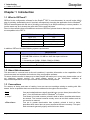
Since in the meantime there exist different versions of DRTconf, please observe that only certain versions
are compatible to the DRT 2:
DRT 2 Version
DRTconf Version
up to 1.01
1.00
1.10 to 1.12
1.10
from 1.20
1.20
from 1.30
1.30 or 1.40
In addition, DRTconf also has following system requirements:
Requirements
PC
•
•
•
•
IBM compatible PC, minimum Pentium processor
256 MB RAM minimum, 20 MB free hard disk space minimum
mouse
1 free serial port (COM1, COM2, COM3 or COM4)
Monitor
• resolution 640 x 480 Pixel minimum, 256 colours minimum
Operating system
• Microsoft Windows® 2000/XP
1.2 About this document
This document is a manual and on-line aid combined. It provides information on the capabilities of the
room thermostat and explains the functions of the configuration software.
To ensure that the manual is always up-to-date Doepke will assist you in every way: please make use of
our telephone support service, our email update service or the information available at
http://www.doepke.de/uk to be kept informed of all the latest developments.
1.3 Conventions
For reasons of clarity and ease of reading, here are some set markings relating to working with Windows®. As far as possible these conventions are adhered to throughout the document.
Start
Over and underlined terms signify special keys or menu items (also called "buttons"). You will find these either in Windows® or ProLine.
„a:setup“
Text shown in inverted commas, printed in bold or italics, describes what has to
be entered. The inverted commas merely serve as text limit markers and do
not need to be entered.
<File><Save>
Text set in greater than/smaller than symbols, printed in bold or italics,
describes those menu items or menu sequences that are necessary. The specified commands generally signify multi-level menu items.
Page 1
Novmber 2009, Version 1.40
DRTconf User Manual
Doepke
1 Introduction
1.4 Abbreviations and Terminology
1.4 Abbreviations and Terminology
Abbreviation
Description
Checkbox
Box within a dialogue field which may be ticked (activated) or deselected (de-activated). Several checkboxes can be activated simultaneously. See also radiobutton
COM1/COM2/
COM3/COM4
Communication Port: Plug-in connectors on the PC which enable itton be linked to
other communication partners.
Cursor
Marker (pointer or similar) on the screen showing at which point the next input will
be.
FPROM
Flash Programmable Read-Only Memory:
Memory module which, with the application of a voltage, is permanently programmed with data
Icon
Graphic symbol for user programmes, data etc. on the screen.
LCD
Liquid Crystal Display
LED
Light Emitting Diode: A semiconductor diode which emits light.
Object
Denotes in this document a function, i.e. the execution by the software of an input
or output, e.g. a shutter control.
In ProLine many devices have a specific object assigned to them in order to enable
settings to be made which are decisive for the functioning of the device.
PIN
Personal Identifikation Number: In this case a 4-digit number to disable the access
to the system menu or switching digital channels.
ProLine
Configuration programme for channel generators DKG 1 and DKG 2.
ProLineNG
Configuration programme for channel generators DKG 20 and DKG 21-GSM. In
this document the terms ProLine and ProLineNG always refer to the ProLineNG version for the new DKGs.
Radiobutton
For the selection of several activating fields only one of which can be called up at
any one time.
1.5 Documents Used
Reference
Description
Order No.
[1]
Dupline
Product Information and Planning Aid
5 900 082
[2]
ProLine User Manual
5 900 126
[3]
ProLineNG
5 900 142
[4]
DRT 2 Operating Instructions
DRTconf User Manual
User Manual
3931272
Novmber 2009, Version 1.40
Page 2
2 Quick Start
2.1 Start Simply - Step by Step to Creating your own DRT 2 Configuration
Doepke
Chapter 2 Quick Start
2.1 Start Simply - Step by Step to Creating your own DRT 2 Configuration
In this chapter we want to provide you with an easy introduction to DRTconf by explaining in simple-to-follow steps the configuration procedure. For each of these steps there is detailed information provided in
the following main chapters to which you can refer if necessary.
Have fun!
2.1.1 Starting DRTconf
Once installation has been successfully accomplished the programme can be started. The link-up to the
programme can be found in the Windows menu under <Start><Programs><Doepke Schaltgeraete><DRTconf>.
2.1.2 The User Interface
The following illustration presents the programme user interface with a loaded configuration file which
already contains the most important functions:
Menu
Toolbar
Download to DRT
Upload from DRT
Display Group
Read Device Info
Display Settings
Display of key
lock/PIN protection
Dupline Addresses
Add a channel
Display texts
Move channel up
Move channel down
Help
texts
2.1.3 Selecting the Programme Language
If the programme language in which DRTconf has been started is not the right one, you can always
Page 3
Novmber 2009, Version 1.40
DRTconf User Manual
Doepke
2 Quick Start
2.1 Start Simply - Step by Step to Creating your own DRT 2 Configuration
change it in the <Options><Language> menu.
2.1.4 Display Settings
It is important to establish the correct settings for the DRT 2 at the start, as these will directly affect its subsequent operation and function.
2.1.4.1 Basic Settings
Menu
Keyboard
<Display><Settings><Basic Settings>
Alt+Ctrl+S
1. If you wish, you can enter general information relating to the text display in the <Project
Description> box. This may help you later to identify the installation site or the application in
addition to the file name.
2. Now decide upon the operating mode of the <Background Light>: it is often advisable for
this to be illuminated for a short time when a key is pressed, so that the text can be read even
in darkness.
3. Select the <Language> of the DRT system menu - for English-speaking countries this would
normally be the standard "English".
4. If you want to protect the display against accidental or unauthorized operation, e.g. by children, either select the <Pressing 2 Keys> option or force the input a PIN by means of the
option <PIN> in the field „Key Lock“.
In both cases it is necessary to switch on the key lock at each single object (e.g. Dupline
channels) which is to be locked.
5. Exit the dialogue with <OK>.
2.1.4.2 Controller Functions
Menu
Keyboard
<Display><Settings><Controller Functions>
Alt+Ctrl+S
1. Specify here in which operating mode the DRT shall work: Controller or Terminal. The most
common case of operation will be the „Controller“, since he controls the temperature of the
room on his own. If you selected „Controller“ the setting of items 3 and 4 is not available.
2. In the field „Temperature Calibration“ you may eventually compensate an offset caused by
the temperature measurement of the DRT. Most likely the measured value is higher than
effective room temperature value due to the intrinsic heating by flush-mounted fitting.
3. In the field „Frost/Heat Protection“ you may specify the limits for the automatic protection
against overheating or frost.
4. In the field „Controller Reset“ enter a Dupline address to give the possibility of a reset via the
Dupline bus to the default values which may have been changed manually at the DRT.
2.1.5 Configure the Room Thermostat
2.1.5.1 General
But now to the most important task that you can perform DRTconf: The configuration of the thermostat
DRTconf User Manual
Novmber 2009, Version 1.40
Page 4
2 Quick Start
2.1 Start Simply - Step by Step to Creating your own DRT 2 Configuration
Doepke
function.Therefor, some so-called „temperature programmes“ are at your disposal, which you may insert
on two ways:
a. By inserting with the right mouse button („Add“)
b. By the command
Note:
Not always all programmes are available: The availability depends on the place where you try
to insert the programme and if it already has been utilized (many programmes may only be
configured once).
2.1.5.2 Configuring Thermostat Channels (Objects)
To configure the DRT to be a thermostat you require one of the programmes „Heating Setpoint“ or „Cooling Setpoint“ in any case. The configuration is similar for both programmes:
Dupline Address
(Relay for Valve)
Displayed Text
Lowest adjustable value
Key / PIN lock
Default value (e.g. after reset)
Highest adjustable value
The following programmes are available:
Page 5
Novmber 2009, Version 1.40
DRTconf User Manual
Doepke
2 Quick Start
2.1 Start Simply - Step by Step to Creating your own DRT 2 Configuration
2.1.5.3 Programmes in „Controller“ Operating Mode
Actual Value - Room Temperature
Description
Current measurement of the room temperature as used by the DRT 2 to regulate same. If this object has not been configured the automatic control will
process this value internally.
Range of values 0..45°C
Address
ProLine object
A1..P8
Transmitted analogue (AnaLink®) data, measuring range 0..45°C
Analogue sensors | temperature sensor
Measuring range 0..45ºC
Set Value "Heating"
Description
Setting range
Address
ProLine object
Remarks
Desired minimum temperature (heating value).
10..30°C
A1..P8
Transmitted digital data ("Heating unit" On/Off)
Push-button function for operating a heating unit
Must be 2 K (ºC) below the „Cooling set value“.
Set Value "Cooling"
Description
Setting range
Address
ProLine object
Remarks
Desired maximum temperature (cooling value).
10..40ºC, manually at the device
A1..P8
Transmitted digital data ("Cooling unit" On/Off)
Push-button function for operating a cooling unit
Must be 2 K (ºC) above the “Heating set value“
Thermostat Inhibit
Description
Setting range
Address
ProLine object
Remarks
Stops the internal processing of the automatic control and results in the deactivation of all switching channels that may have been set.
On / Off, manually at the device or via the Dupline bus
A1..P8
Received digital data (thermostat inhibit On/Off)
Push-button function
Priority above all other operating modes (inc. manual thermostat inhibit);
Deactivates the frost/heat protection.
Night-Time Lowering
Description
Setting range
Address
ProLine object
DRTconf User Manual
Enables a manually selected, or Dupline controlled, reduction in the room
temperature (heating mode) or increase in the room temperature (cooling
mode) by a configurable value.
Lowering value: 1..10 K (ºC)
Status: On/Off (manually at the device or via the Dupline bus)
A1..P8
Received digital data (thermostat inhibit On/Off)
Push-button function, time switch or similar.
Novmber 2009, Version 1.40
Page 6
Doepke
2 Quick Start
2.1 Start Simply - Step by Step to Creating your own DRT 2 Configuration
Remarks
A manual, temporary disabling of the lowering can be achieved via the party
setting;
A manually activated lowering of the temperature will be overridden by the
next command for switch-off via Dupline.
Comfort (Party) Setting
Description
Setting range
Address
ProLine object
Remarks
Enables a Dupline controlled command for night-time lowering to be temporarily invalidated so that the room temperature corresponds to the selected set
value.
0.5..5 hours / Off / On
none
Push-button function, time switch or similar.
If, after expiration of the set time, a command for lowering via Dupline is still
pending, then this will be executed.
2.1.5.4 Programmes in „Terminal“ Operating Mode
Actual Value - Room Temperature
Description
Current measurement of the room temperature that is required by a superset control facility for regulating the temperature.
Range of values 0..45°C
Address
ProLine object
Remarks
A1..P8
Transmitted analogue (AnaLink®) data, measuring range 0..45°C
Analogue sensors | temperature sensor
Measuring range 0..45ºC
Has to be configured.
Set Value "Heating"
Description
Desired minimum temperature (heating value) which is transmitted to the superset control facility.
Setting range 10..30°C
Address
ProLine object
Remarks
A1..P8
Transmitted analogue (AnaLink®) data, measuring range -30..60°C
Analogue sensors | temperature sensor,
Measuring range 0..45ºC
Must be 2 K (ºC) below the „Cooling set value“.
Set Value "Cooling"
Description
Desired maximum temperature (cooling value) which is transmitted to the superset control facility.
Setting range 10..40°C
Adresse
ProLine object
Description
Page 7
A1..P8
Transmitted analogue (AnaLink®) data, measuring range -30..60ºC
Analogue sensors | temperature sensor,
Measuring range 0..45ºC
Must be 2 K (ºC) above the „Heating set value“.
Novmber 2009, Version 1.40
DRTconf User Manual
Doepke
2 Quick Start
2.1 Start Simply - Step by Step to Creating your own DRT 2 Configuration
2.1.6 Configuring Dupline Channels
In addition to the thermostat programmes you can basically configure up to 16 Dupline channels, whereby
the sequence of configuration is initially of no consequence (you can specify this later by simply moving
them.
The creation of those channels is done as described in chapter 2.1.5.1 on page 4 by insertion of the
„Dupline Channel“ object. Then configure the channel by proceeding in the following steps:
2.1.6.1 Digital Channels (Switching/Shutter Channels)
1. For the type of representation select <Digital value> on page <Basic Settings>.
2. In field <Dupline Address> set the address of the channel to be displayed.
3. Specify the function:
– Select <Switching channel> for push-button, toggle functions or similar.
– Select <Shutter/ Shutter Master> if it is a shutter control or a shutter master control.
With this setting DRTconf will automatically block the next channel, as both the Up
and Down channels are operated under the uneven address.
– You should therefore answer "OK" to the question asking whether the next channel is
to be deleted.
4. If the digital channel is to be operational then tick the <Unlocked> option as operation type.
5. Now switch to the page <Display Settings>.
6. Now enter the <Descriptive Text> which is to be displayed. The embedded display shows
how the text will look.
7. Then specify the <Status Text> for the channel status:
– In the case of switching channels this is normally "On" or "Off"; with shutter control
objects it is "Up" or "Down".
– Tip: By activating the <Default> button the above data will be set automatically.
8. Finished!
2.1.6.2 Analog Channels
1. In the case of an analog channel (temperature or light level sensor) select <AnaLink Value>
as the type of representation.
2. Specify the function as follows:
– Enter the minimum and maximum values in the <Sensor Input Range> boxes;
– Select <Light Level Function> if it concerns the analog value of a DLUX (in which
case the light level range will automatically be set).
3. Now switch to the page <Display Settings>.
4. Now enter the <Descriptive Text> to be displayed. The embedded display shows you how
the text will look.
5. Then specify in the <Status Text> box the unit to be displayed:
– With analog data this is normally either "ºC" or "Lux".
– Tip: By activating the <Default> button the above data will be set automatically.
6. Finished!
2.1.7 Transferring the Configuration
Once all required channels have been configured the complete application can be transferred:
1. Proceed via the <Options><Communication> to switch on the PC connection (COM port),
which is linked to the DRT 2 via the DKK 1 serial cable.
DRTconf User Manual
Novmber 2009, Version 1.40
Page 8
2 Quick Start
2.1 Start Simply - Step by Step to Creating your own DRT 2 Configuration
Doepke
2. For the transfer select the command <Display><Download> in the menu and press this button:
2.1.8 Saving the Configuration
Last of all, you should now save your work so that you may change it later or use it for other projects. For
this purpose select <File><Save ...> or <File><Save as ...> or press this button
Page 9
Novmber 2009, Version 1.40
DRTconf User Manual
Doepke
3 Operation
3.1 General Information
Chapter 3 Operation
3.1 General Information
With DRTconf a user interface has been created which, while kept deliberately simple, at the same time
offers all possible options for configuring the DRT 2.
The main features of DRTconf are
• little menu depth,
• efficient shortcut keys, and
• Help functions.
To summarize: DRTconf can be called an easy-to-operate "tool" - and, as with any tool, it is necessary to
learn how to operate it. This chapter is designed to support you in this task.
3.2 Retrieving and Exiting
3.2.1 Starting
After the successful installation you will see in the Windows® start-up menu below the <Start><Programmes><Doepke Schaltgeraete><DRTconf> the icon for DRTconf, which looks as follows:
DRTconf 1.4x
Click with the mouse on this entry or select it with the keyboard and DRTconf will start.
DRTconf User Manual
Novmber 2009, Version 1.40
Page 10
Doepke
3 Operation
3.2 Retrieving and Exiting
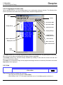
3.2.2 Programme Construction
Having started DRTconf, you are straight away in the configuration dialogue window. The following illustration represents the construction in principle with a loaded configuration file:
Menu
Toolbar
Download to DRT
Upload from DRT
Display Group
Read Device Info
Display Settings
Display of key
lock/PIN protection
Dupline Addresses
Add a channel
Display texts
Move channel up
Move channel down
Help
texts
The menu enables you to access the general functions of the programme, e.g. opening and saving files.
Here you can also enter the settings for the display and the language.
The toolbar makes many functions directly available by clicking on them with the mouse; this will save
you a lot of time when editing.
The status line at the bottom edge of the programme dialogue window is extremely informative: here brief
help texts will be displayed.
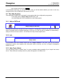
3.2.3 Exit
Menu
Keyboard
<File><Exit>
Alt+F4
There are three ways of exiting from DRTconf:
1. By using the menu sequence <File><Exit>,
2. By clicking on the "X" in the upper-right hand corner of the left programme window, or
Page 11
Novmber 2009, Version 1.40
DRTconf User Manual
Doepke
3 Operation
3.3 The Help System
3. By using the shortcut keys Alt+F4
It is immaterial which way you choose, in each case you will be asked whether you want to save any
changes made to the configuration data before you exit.
3.3 The Help System
The help system makes itself "noticeable" at two points within the configuration programme:
• In the Help menu (<Help><Help to DRTconf>), and
• As a brief help text ("hint") available for each setting option.
3.3.1 Help to DRTconf
Menu
Keyboard
<Help><Help to DRTconf>
F1
Selecting this menu item will open this file as a help file. It reflects the contents of the manual for DRTconf
which is supplied with the software-package in the form of a PDF file and is available for downloading always in its most current version - on the Internet at http://www.doepke.de/uk.
3.3.2 Info
Menu
Keyboard
<Help><Info>
For information about this software select the entry <Help><About> in the menu. Here you will find the
programme version used, together with information about ourselves, the firm of Doepke Schaltgeräte
GmbH & Co KG.
3.3.3 Help Texts (Hints)
You can find help texts, so-called "hints", for every available setting possibility if you "swipe" the mouse
over it. These hints are normally shown in yellow and appear in the status line.
DRTconf User Manual
Novmber 2009, Version 1.40
Page 12
Doepke
3 Operation
3.4 Files
3.4 Files
DRTconf normally opens and saves files with the ending "drt". Such files can be opened, saved and
stored under a new name in the <File> menu.
3.4.1 Starting a new File
Menu
Keyboard
<File><New>
Ctrl+N
With the command <File><New> you can start a completely new application at any time. DRTconf then
proceeds as follows:
• If a new configuration had previously been started, or an opened file been changed, it offers
the option of saving these data.
• It then deletes all objects (headers, temperature programmes and Dupline channels).
• It deletes the settings for the DRT 2 (with the exception of the selected menu language, see
Chapter 4.1 "Display Settings" on Page 26).
• This will not affect the programme options, such as e.g. the selected serial port.
Note:
DRTconf assigns to a new file a name dependent upon those files which already exist in the
route in which the file last opened or saved is located. It normally assigns new files the name
"unknownxx.drt" whereby xx represents a unique number.
Example: You have already saved two files in the memory named "unknown1.drt" and
"unknown2.drt" respectively. If you click <File><New> DRTconf will then generate the file
name "unknown3.drt" thereby preventing accidental overwriting/replacing.
3.4.2 Opening an Existing File
Menu
Keyboard
<File><Open>
Ctrl+O
As in many of the other Windows® applications you can retrieve an existing file in of various ways:
• Via the command <File><Open>: A dialogue will then appear via which you can navigate on
your hard disk.
• Via the "history" in the <File><Recent File(s)> menu: here up to 9 of the files last opened will
be shown and can be selected directly.
• By means of the "drag-and-drop" method: By pulling a DRT file from e.g. the workstation to
the programme area you are instructing DRTconf to open this file. However, you must always
ensure that that you are dealing with a DRT configuration file.
3.4.3 Saving Files
Menu
Keyboard
<File><Save>
<File><Save as...>
Ctrl+S
With the <File><Save> menu item you can save new and modified applications on hard disk or floppy. If
this file already exists it will be overwritten; if it is a new file you will be asked for a file name.
The <File><Save as...> menu item however enables you to save the current application under another
Page 13
Novmber 2009, Version 1.40
DRTconf User Manual
Doepke
3 Operation
3.4 Files
name. So, here too, you will be asked to specify a file name.
3.4.4 Printing Files
Menu
Keyboard
<File><Print...>
Ctrl+P
With the <File><Print...> menu item you can output the configuration data currently edited on a printer.
The dialog which appears on selection of this menu item conforms to the standard in Windows® applications. However, the dialog may vary dependent on the selected printer’s functions.
Note:
The dialog’s page indications refer to the configured display channels with their order of
appearance, they not refer to the printed pages of paper.
3.4.5 Displaying File Properties
Menu
Keyboard
<File><Properties>
The <File><Properties> menu item offers information about the configuration file currently edited:
Following information is available:
Filename:
Designation and path of the file opened. You can scroll the text by clicking into the field if the path is longer
than the displayable text.
File created:
Date and time of file creation. This value is stored in the DRT.
Last transfer:
Date and time of the last transfer to DRT. This value is updated on each transfer and is stored in the file as
well as in the DRT.
DRTconf User Manual
Novmber 2009, Version 1.40
Page 14
Doepke
3 Operation
3.5 Formatting Text
3.5 Formatting Text
3.5.1 General Information
For the purpose of formatting texts in the text input boxes, such as e.g. descriptive text, DRTconf provides
some useful functions. The prerequisite for the availability of these functions is, however, that the cursor is
located in such a box, i.e. that you have clicked with the mouse in such a box, or that you have jumped
there with the Tab key.
The display permits input of some special characters:
• The umlauts: "ä", "ö", "ü", "Ä", "Ö", "Ü"
• The German sharp s: "ß"
• Special units: "º", "%" and "?".
Entering other special characters may result in an incorrect representation in DRT, even if these are
shown correctly in the preview in DRTconf.
3.5.2 Cutting
Menu
Keyboard
<Edit><Cut>
Ctrl+X
With this command you will cut out and at the same time copy the selected text; you can later insert it e.g.
in another box.
3.5.3 Copying
Menu
Keyboard
<Edit><Copy>
Ctrl+C
With this command you will copy the currently selected text; you can later insert it e.g. in another box.
3.5.4 Pasting
Menu
Keyboard
<Edit><Paste>
Ctrl+V
With this command you can insert a previously copied text. Such text may originate from another box or
from e.g. a word processing programme. Text once copied or cut may be inserted as often as required.
3.5.5 Align Left
Menu
Keyboard
<Edit><Align Left>
Ctrl+L
With this command you will left align the text in a box. All texts are normally left aligned in DRTconf when
first entered. However, if you have employed one of the instructions "Center" or "Align Right" you can
always revoke them with this command.
Page 15
Novmber 2009, Version 1.40
DRTconf User Manual
Doepke
Note:
3 Operation
3.5 Formatting Text
It is only possible to left align if the length of the entered text is shorter than the maximum
number of characters of the text box in question.
3.5.6 Center
Menu
Keyboard
<Edit><Center>
Ctrl+M
With this command you will centre the text in a box. This command is particularly helpful if texts are to be
centrally positioned in the display.
Note:
The same spacing right and left can only be achieved if the text consists of an even number
of characters as the input boxes are also designed for an even number. If the text to be
centred has an uneven number of characters, it will be aligned with one character shifted to
the left.
3.5.7 Align Right
Menu
Keyboard
<Edit><Align Right>
Ctrl+R
With this command you will right align the text in the text box.
Note:
It is only possible to right align if the length of the entered text is shorter than the maximum
number of characters of the text box concerned.
DRTconf User Manual
Novmber 2009, Version 1.40
Page 16
Doepke
3 Operation
3.6 Configuring the Objects
3.6 Configuring the Objects
3.6.1 General Information
With the aid of DRTconf you can represent Submenus, temperature programmes and up to 16 Dupline
channels which generally means a sufficient number.
3.6.2 Creating a Channel
The creation of an object either might be done by clicking the right mouse button in the „Display Configuration“ field (e.g. <Add><Dupline Channel>) or by pushing the button „Add Channel“ respectively the
menu item <Edit><Add>;
Insert a channel:
By clicking right mouse button
Insert a channel:
By clicking „Add a channel“ button / <Edit><Add> menu item
Page 17
Novmber 2009, Version 1.40
DRTconf User Manual
Doepke
3 Operation
3.6 Configuring the Objects
3.6.3 Configuration of Dupline Channels
After creation of a Dupline channel with the alternatives described above, you may configure this one by
double clicking on the element.
3.6.3.1 Digital Value
Digital Value:
Basic Settings
If you are using the channel to be configured as a digital value channel, you have the following options:
Switching Channel
The channel is a normal switching channel. This setting can be used for all Dupline switching channels with the exception of shutter control objects - i.e. for push-button functions, toggle-switch functions, timers, alarm objects etc.
In the case of channels which are not user operated, e.g. an alarm signal, then only the status which you
have configured will be displayed. Please refer to Appendix A - Configuration System.
Shutter/Shutter Master
This channel is a shutter control channel. If you are configuring a channel as a shutter control channel,
DRTconf will automatically link it to the next channel. Shutter control channels always start with an uneven
address (A1, A5 ...) for the "Up" command, and the follow-on address (A2, A6 ...) is always the "Down"
command. In order to avoid unnecessary leafing through the pages in DRT 2, both channels are combined by DRTconf, so that "Up" can be controlled by the left middle button and "Down" by the right middle
button.
Please note that the status shown with shutter objects is only valid while the Up or Down command is
being carried out.
DRTconf User Manual
Novmber 2009, Version 1.40
Page 18
Doepke
3 Operation
3.6 Configuring the Objects
Operation
Irrespective of the type of channel involved, you have the option to define the type of operation:
Operation
<Unlocked> Generally the channel can be operated, even if the lock has been activated
in the „Display Settings“.
<Key/PIN-Lock> With this setting the preset in „Display Settings“ is important: If there a key
lock has been specified, this also has to be performed when a channel
shall be operated; the same applies to the PIN lock.
<Locked> Independent from the „Display Settings“ the configured channel never can
be operated.
Dupline Address
Here you determine which Dupline address shall be switched and which address shall be displayed. In
each case the address range lies between A1 and P8.
Addresses
<Operate/Display> Insert here the channel address that shall be operated in case of pressing
the push button at the DRT.
The DRT will show the status of this channel unless the option <Different
Display Channel> has been selected.
Note:
Whether or not the channel can be influenced depends upon its configuration in the channel generator. Refer to Appendix A - Configuration System to see which channels can be influenced.
<Other Display Address> If you choose this option you may specify a channel address in the field
below which status will be displayed instead of the address specified in the
field <Operate/Display>.
This for example is reasonnable when using dimmers on which the manipulation generally is done on a different channel than the acknowledgement.
Page 19
Novmber 2009, Version 1.40
DRTconf User Manual
Doepke
3 Operation
3.6 Configuring the Objects
3.6.3.2 AnaLink Value
AnaLink Value:
Basic Settings
If you are using the channel to be configured as an AnaLink value channel, you have the following
options:
Light Level Function
This channel is used for transmitting light level data. When this option is selected DRTconf will automatically insert the correct limit values for the input range.
Note:
Always select "Light Level Function" and not the option "Other" for the light level sensor. The
light level value cannot be linear-computed and the wrong data would thus be displayed by
the DRT, if the setting "Other" were chosen.
Other
You have configured this channel for the transmission of AnaLink data which are not light level values.
The former include e.g. temperature sensors or general sensor values which are fed into the system via
standard input modules (0...10 V, 4...20 mA).
In such cases please also enter the relevant sensor input range so that the data can be correctly scaled
by the DRT.
Sensor Input Range
The sensor input range serves as the basis for scaling and displaying analog data by the DRT. Here you
should enter the same data as you also use in ProLine - they equate to the sensor's measuring range. If
you are using e.g. a temperature sensor with a measuring range of -10ºC to +100ºC then these figures
must also be entered in the “Min“ and “Max.“boxes.
Dupline Address
Here you determine on which Dupline address the analog value is transmitted. The address range lies
between A1 and P8.
DRTconf User Manual
Novmber 2009, Version 1.40
Page 20
Doepke
3 Operation
3.6 Configuring the Objects
Note:
If you want an analog value to be displayed, then the "Control Output" option must not be
activated in ProLine or ProLineNG.
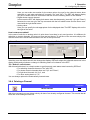
3.6.3.3 Descriptive / Status Text in Display
Display:
Descriptive Text - Status Text - Digital Value
Display:
Descriptive Text - Status Text - AnaLink Value
In the "Display Settings" options window you determine the DRT display settings for the selected channel.
These are normally independent from the selected channel type. The greenish display offers you a prior
chance to check the appearance of the settings beforehand without having to download the configuration
to the DRT.
You can use special characters in all the boxes; please refer to Chapter 3.5.1 "General Information" on
Page 15.
Descriptive Text
Here you should enter a descriptive designation for the switched electric load or the displayed analog
value. For this purpose the display provides space for 16 characters. To prevent confusion when leafing
through the DRT at a later date you should avoid assigning the same designation several times over.
Status Text
The boxes for the "Status Texts" group are located in the bottom line of the DRT. All boxes are limited to
four characters, but differ according to the selected data type:
• Digital switching channel:
Page 21
Novmber 2009, Version 1.40
DRTconf User Manual
Doepke
3 Operation
3.6 Configuring the Objects
Here you can make two entries for the status values: the text for the channel status when
switched on, and when switched off (normally "On" and "Off"). The DRT will always display
only one of these entries in accordance with the current switching status of the channel.
• Digital shutter control channel:
In this case the DRT will display both status texts simultaneously (normally "Up" and "Down")
because the user can give the Up command with the left inside button and the Down command with the right inside button.
• Analog value:
Here you can specify the unit appropriate for the displayed data. The DRT displays this unit to
the right of the value.
How is status text edited?
In the case of units for an analog value it is quite clear: here there is only one input box. It is different for
switching or shutter channels, for here you have two text boxes. To edit one of the two texts simply click
with the mouse the relevant switch button to the left of the input boxes:
Status Text
Simulate / Edit
Switching over the status text will also change the display: DRTconf adopts the selected status text in the
display and thereby simulates a change in switching status of a channel in the DRT.
The "Default" switch button
With this switch button it is a simple matter to get frequently used status texts inserted by DRTconf:
• For switching channels these are "On" and "Off";
• For shutter control channels these are "Up" and "Down";
• For light level channels it is "lux", and
• For other analog data it is "ºC".
You can always replace the automatically inserted texts.
3.6.4 Deleting a Channel
Menu
Keyboard
<Edit><Delete>
DEL
With this command you can delete entirely all data of an already configured channel. This means that all
texts and event settings will be lost.
DRTconf User Manual
Novmber 2009, Version 1.40
Page 22
Doepke
3 Operation
3.6 Configuring the Objects
3.6.5 Moving Channels
Menu
Keyboard
<Move Up/Down>
With this push button you may move up or down the currently selected channel (provided that the current
position allows this).
Tip:
Page 23
You may also move the channels by „Drag-and-drop“: Therefor click on the channel and pull it
to the desired position, keeping the mouse button pressed.
Novmber 2009, Version 1.40
DRTconf User Manual
Doepke
3 Operation
3.7 Reading Device Info, Reading and Writing a Configuration
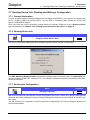
3.7 Reading Device Info, Reading and Writing a Configuration
3.7.1 General Information
In order to enable a data exchange between the text display and DRTconf, you require a connection from
the PC (COM or USB port) and the DRT 2. Use the DDK 1 connecting cable (Order No. 09 501 129)
and/or a USB-RS232 adaptor.
Once you have set up the connection, please select the relevant COM port in the <Options><Port>
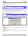
menu as described in Chapter 4.2.2 "Setting Up the Communication Port" on Page 30 .
3.7.2 Reading Device Info
Menu
Keyboard
<Display><Read Device Info>
Ctrl+I
The device information displays the DRT operating system version and the current status.
Device Information
The DRT Operating System Version denotes the software state of the thermostat. The Status bits indicate the condition of the DRT - the figure "01", for example, indicates that the bus connection of the thermostat is functional.
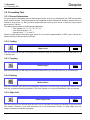
3.7.3 Reading the Configuration
Menu
Keyboard
<Display><Upload>
Ctrl+U
With this command you can read the current configuration of the DRT. If there is no project, then the read
channels will not be configured. Only the display settings will reflect the current settings in the DRT system menu.
You will, however, be requested to save the previous configuration if you have configured channels in
DRTconf beforehand.
DRTconf User Manual
Novmber 2009, Version 1.40
Page 24
3 Operation
3.7 Reading Device Info, Reading and Writing a Configuration
Doepke
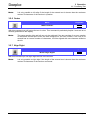
3.7.4 Writing the Configuration
Menu
Keyboard
<Display><Download>
Ctrl+D
With this command you can transfer your current configuration to the DRT. Please note that no further
safety requests will be shown and that any existing configuration in the DRT will immediately be overwritten.
Note:
Please ensure that neither the power supply nor the connection between DRT and PC can be
disrupted during the transfer. A break in communication will result in an incorrect
configuration.
You can, of course, always repeat the download after a disruption.
Page 25
Novmber 2009, Version 1.40
DRTconf User Manual
Doepke
4 Settings
4.1 Display Settings
Chapter 4 Settings
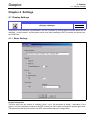
4.1 Display Settings
Menu
Keyboard
<Display><Settings>
Alt+Ctrl+S
Irrespective of the channels' representation, the DRT provides for several basic functions which can be
changed - to some extent - via the system menu even after installing the DRT, but which can also be preset in DRTconf:
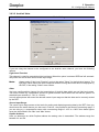
4.1.1 Basic Settings
Project Description
This box gives you the chance of entering a brief - up to 64 characters in length - description of the
project, or of the installation location of the DRT so that you will be able to identify the project again later.
The entered text will also be saved in the DRT when downloading the configuration.
DRTconf User Manual
Novmber 2009, Version 1.40
Page 26
Doepke
4 Settings
4.1 Display Settings
Background Light
Here you can specify the operating mode of the background lighting:
Background Light
<Always Off> The background lighting stays permanently off.
<Always On> The background lighting stays permanently on.
<On Pressing Button>
The background lighting is switched on when one of the buttons on the
front of the DRT is pressed, and automatically goes off again after the
elapsed time specified in minutes. Permissible are the values from 1 to 20
minutes.
Note:
Due to the heat produced by the LEDs, the switching status of the background lighting has a
significant influence on the correction value. This means that you’ll have to re-adjust the
correction value after approx. 30 min when you’ve changed the operating mode of the
background lighting.
Note:
DRT with blue display (starting with version 1.40) ignore the option <Always off> and instead
of this switch on the lighting on pressed button.
System Menu
System Menu
<Hide> When activating this option the system menu will not be accessible anymore - neither by clearing the key lock nor by entering a PIN.
<Language> Here you can specify the language of the system menu in the DRT.
Ex-works, the DRT solely is equipped with the english version of the system menu. By specifying the corresponding language at this setting the
menu language will be changed.
Key Lock
The key lock option is intended to prevent unintentional operation of channels when contact with the DRT
is made by accident.
Key/PIN lock
Page 27
<None>
Neither the system menu nor digital channels are protected by an interlock.
<Pressing 2 keys>
The access to the system menu simply is protected by scanning two buttons (lower and upper right-hand buttons). Channels with activated option
<Key-/PIN-Lock> are protected as well.
<PIN>
The operation of the system menu is protected by the request of a 4-digit
PIN 4-stelligen PIN geschützt. Channels with activated option <Key-/PINLock> are protected as well.
Novmber 2009, Version 1.40
DRTconf User Manual
Doepke
4 Settings
4.1 Display Settings
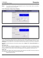
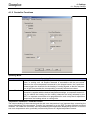
4.1.2 Controller Functions
Operating Mode
Operating Mode
<Controller>
In the „Controller" mode the DRT 2 operates independently and controls the heating
valve, or cooling unit, via Dupline channels in accordance with the set values.
Based on the room temperature measured by the integral sensor, the 2-point thermostat triggers the channels for the heating or cooling signals so that the temperature of the room reaches the corresponding, manually selected set values.
<Terminal> In the "Terminal" mode the thermostat simply measures the room temperature and
transmits it, together with the desired temperature settings, to a superset control circuit. As neither the heating nor the cooling channels are being activated by the
DRT 2, a superset control has to be programmed in such a way that it adjusts the
temperature via heating valves or cooling units.
Temperature Calibration / Calibration Value
The exact matching of the measured and the real room temperature is an important item concerning the
correct functioning of the thermostat. Therefor it is necessary to run the DRT 2 at least 30 min in mounted
condition. You obtain the correction value by subtracting the temperature displayed by the DRT 2 from the
true room temperature value, preferably measured by means of a digital temperature sensor.
DRTconf User Manual
Novmber 2009, Version 1.40
Page 28
Doepke
4 Settings
4.2 Programme Settings
Example:
• Measured temperature: 21.5°C
• Temperature displayed by DRT 2: 24.5°C
• Correction value to be adjusted: -3.0 K (°C)
You may enter the correction value within the system menu of the DRT 2 directly - but it will be overridden
when transferring a new configuration to the DRT. It is more reasonable to store the value directly in the
system settings here.
Frost/Heat Protection
The frost/heat protection programme provides for the room temperature to be controlled at the outer temperature limits. Upon reaching the limits set via DRTconf, the thermostat will activate the relevant heating
or cooling channel.
Frost/Heat Protection
<Frost protection If the room temperature falls below the value specified here, the DRT automatibelow> cally activates the channel for heating.
<Heat protection If the room temperature passes over the value specified here, the DRT autoabove> matically activates the channel for cooling.
<Protection Enter here the address on which, if activated, the DRT solely executes the conAddress> trol of the room temperature according to the limits of heat/frost protection. Programmes like the night time lowering or comfort mode are overridden by this.
Controller Reset
The thermostat can be returned to a defined initial status via the Dupline bus. When the relevant reset
channel, entered in this field, is transmitted via Dupline, the thermostat discards almost all manually activated changes made hitherto and reloads the original configuration (default settings). An exception of this
are all system settings, i.e. the temperature correction value, the key lock and the back lighting.
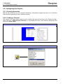
4.2 Programme Settings
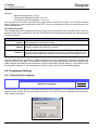
4.2.1 Selecting the Language
Menu
Keyboard
<Options><Language>
Alt+Ctrl+A
DRTconf gives you the option of choosing between different languages. Such language setting becomes
apparent in the menus, the help texts and the help file. If you click on Select Language, the following dialogue window will appear:
Page 29
Novmber 2009, Version 1.40
DRTconf User Manual
Doepke
4 Settings
4.2 Programme Settings
Please don't be surprised if this dialogue is always in English irrespective of the language you have
selected. As many international users are familiar with English as the basic computer language, making
the selection will be easier.
Note:
The selection in this menu may vary, depending upon the translations already provided.
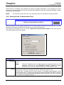
4.2.2 Setting Up the Communication Port
Menu
Keyboard
<Options><Communication><Basic>
Alt+Ctrl+O
With the exception of the communication port for the data transfer between DRTconf and DRT, all other
parameters have been predefined so that you do not need to set these up.
You select the serial port of your PC via the <Options><Communication><Basic> menu item and the
following dialogue window will appear:
Basic Settings
Communica- Choose here the communication port which you want to use for the transmission to the
tion Port device.
Note:
Transmission
Speed
The list of available ports is compiled during the programme start-up. Any
interfaces, such as e.g. the USB-RS232 adaptor, installed or added
subsequently will only be recognized with the next programme start.
Due to compatibility reasons in conjunction with USB converters, a reduction of the
transmission speed was necessary for DRT 2 starting with version 1.20.
DRTconf tests - starting with the current setting - all available speed settings, which
may take some time. To shorten this process you also may identify the DRT 2’s version
(in it’s system menu) and select the appropriate setting manually. You’ll find a description for this in the operating manual.
DRTconf User Manual
Novmber 2009, Version 1.40
Page 30
Doepke
4 Settings
4.2 Programme Settings
Expert
These settings are solely for tracing problems and should only changed in accordance with support personnel of Doepke. Therefor we don’t go into details concerning the choice of settings here.
Page 31
Novmber 2009, Version 1.40
DRTconf User Manual
Doepke
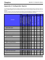
Appendix A - Configuration System
Appendix A Configuration System
The following table illustrates the possible configurations of individual Dupline objects. Naturally, these are
purely recommendations; we do not know how you want to use the functions, that has to be your own
decision.
You are, of course, also free to select the text entries for the description, the status and the events. The
texts given below are commonly used and are also programmed as defaults in DRTconf.
Toggle function
On
Off
Timer
On
Off
Timer, Activation by Pulse
On
Off
Pulse generator
On
Off
(Real-)Time switch
On
Off
Master function
On
Off
Thermostat
On
Off
Night set-back
On
Off
On
Off
Blank, status signal
Push-button function
Push-button function, inverted
Synchronization signal
Sensor Input Range, Max.
Off
Sensor Input Range, Min.
On
Other
Light level Function
AnaLink Value
Off
Allow Operation
On
Shutter/Shutter Master
Switching Channel
Off
Blank
Digital Value
On
Function
Do Not Display
Status Channel “Off“ (Unit)
Analog
Status Channel "On"
Digital
Motion / Proximity Detector
Counter
Time display
Multiplex channel
Shutter control
Up
Down
Shutter master
Up
Down
On
Off
Analog Sensors
Sensor with control output
Temperature sensor
Light level sensor
Wind sensor
DRTconf User Manual
°C
lux
Novmber 2009, Version 1.40
Page 32
Doepke
Appendix A - Configuration System
Sensor Input Range, Max.
Status Channel “Off“ (Unit)
Sensor Input Range, Min.
Status Channel "On"
Other
Measuring device
Light level Function
AnaLink Value
Analog
Allow Operation
Shutter/Shutter Master
Switching Channel
Function
Digital Value
Do Not Display
Digital
ISA Alarms
NCC/NOC
On
Off
Acknowledgement
On
Off
Reset
On
Off
Lamp test
On
Off
Siren
On
Off
Smoke Alarm
NCC/NOC
On
Off
Reset
On
Off
Siren/alarm signal
On
Off
Intruder Alarm
NCC/NOC
On
Off
Enable by code lock
On
Off
Enable by switch
On
Off
Enable by oush button
On
Off
Siren/alarm signal
On
Off
Water Alarm
NCC/NOC
On
Off
Reset
On
Off
Siren/alarm signal
On
Off
Common Siren
On
Off
This option can be utilized.
Although user-operation of this channel is possible, it makes little sense in most cases.
The measuring input range depends upon the sensor used. Dupline temperature sensors frequently
operate within -30ºC to +60ºC or from -10ºC to +100ºC.
The measuring input range of the light sensor is automatically set from 0.1 to 100,000 lux.
Page 33
Novmber 2009, Version 1.40
DRTconf User Manual
Doepke
Index
Index
A
Abbreviations ............................................................... 2
Address
Display/Operation .............................................. 19
Align left ....................................................................... 15
Align right .................................................................... 16
AnaLink value ............................................................ 20
Analog sensors .......................................................... 32
Analog value
Light level sensor .............................................. 20
Other ...................................................................... 20
B
Background light ....................................................... 27
C
Calibration value ....................................................... 28
Center ........................................................................... 16
Channel order ............................................................ 23
Channels
Changing order .................................................. 23
Deleting ................................................................ 22
Protecting ............................................................. 27
Comfort Setting ........................................................... 7
Communication
Disruption ............................................................. 25
Port set up ........................................................... 30
Compatibility ................................................................. 1
Configuration
AnaLink value ..................................................... 20
Analog value ....................................................... 20
Read ...................................................................... 24
Table of objects .................................................. 32
Write ...................................................................... 25
Controller
Operating mode ................................................. 28
Conventions ................................................................. 1
Copying ........................................................................ 15
Cutting .......................................................................... 15
D
Date/Time of transfer ............................................... 14
Default (status texts) ............................................... 22
Descriptive text .......................................................... 21
Device info .................................................................. 24
dimmers ....................................................................... 19
Display
Download ............................................................. 25
Read device info ................................................ 24
Settings ................................................................. 26
Upload ................................................................... 24
DRT
DRTconf User Manual
Operating system version ........................... 1, 24
Reading configuration ...................................... 24
Settings ................................................................. 26
Status .................................................................... 24
Writing configuration ......................................... 25
DRTconf
Exit ......................................................................... 11
Starting .................................................................. 10
Version compatibility ........................................... 1
What is DRTconf? ............................................... 1
E
Edit
Align left ................................................................ 15
Align right ............................................................. 16
Center .................................................................... 16
Copy ....................................................................... 15
Cut .......................................................................... 15
Delete channel ................................................... 22
Paste ...................................................................... 15
Exit ................................................................................. 11
F
File
Exit ......................................................................... 11
New ........................................................................ 13
Open ...................................................................... 13
Print ........................................................................ 14
Properties ............................................................. 14
Save ....................................................................... 13
Save as... ............................................................. 13
Formatting text ........................................................... 15
Frost protection ......................................................... 29
H
Heat protection .......................................................... 29
Help ............................................................................... 12
Help to DRTconf ................................................ 12
Info ......................................................................... 12
Help system ................................................................ 12
Hiding system menu ................................................ 27
I
Info ................................................................................. 12
Input range (sensors) .............................................. 20
Intruder alarm ............................................................. 33
ISA alarms ................................................................... 33
K
Key/PIN lock ............................................................. 3, 4
Basic setting ........................................................ 27
Digital channels .................................................. 19
L
Language
DRT system menu ............................................ 27
DRTconf programme language .................... 29
Novmber 2009, Version 1.40
i
Doepke
Index
Selecting ............................................................... 29
Light level sensor ...................................................... 20
M
Max value .................................................................... 20
Min value ..................................................................... 20
N
Night-Time Lowering .................................................. 6
O
Objects
Comfort (Party) Setting ...................................... 7
Configuring .......................................................... 17
Definition ................................................................. 2
Night time lowering .............................................. 6
Room temperature .............................................. 6
Set value cooling ................................................. 6
Set value heating ................................................. 6
Thermostat inhibit ................................................ 6
Operating Mode
Thermostat/Terminal ........................................ 28
Operating system ...................................................... 24
Options
Communication .................................................. 30
Language ............................................................. 29
Other (Analog value) ................................................ 20
P
Party Setting ................................................................. 7
Pasting ......................................................................... 15
Printing files ................................................................ 14
Programme
Construction ........................................................ 11
Settings ................................................................. 29
Project description .................................................... 26
Properties of files ...................................................... 14
Protection (frost/heat) .............................................. 29
Protection address ................................................... 29
Programme language .......................................29
Shutter/shutter master .............................................18
Simulate/edit ...............................................................22
Smoke alarm ..............................................................33
Starting .........................................................................10
Status ............................................................................24
Status text ....................................................................21
Switching channel .....................................................18
System menu
Hiding .....................................................................27
language ...............................................................27
System requirements .................................................1
T
Temperature calibration ..........................................28
Terminal operating mode .......................................28
Terms ..............................................................................2
Texts
Align left ................................................................15
Align right ..............................................................16
Center ....................................................................16
Copying .................................................................15
Cutting ...................................................................15
Pasting ...................................................................15
Thermostat ..................................................................32
Inhibit .......................................................................6
Operating mode ..................................................28
Reset ......................................................................29
Timer .............................................................................32
V
Version ...........................................................................1
Configuration file ................................................14
DRTconf ................................................................12
W
Water alarm ................................................................33
Q
Quick Start .................................................................... 3
R
Requirements ............................................................... 1
Reset (controller operating mode) ....................... 29
Room temperature display ....................................... 6
S
Sensor
Analog ................................................................... 32
Input range ........................................................... 20
Set Value
Cooling .................................................................... 6
Heating .................................................................... 6
Settings
Basic settings of DRT ....................................... 26
DRT system language ..................................... 27
ii
Novmber 2009, Version 1.40
DRTconf User Manual
Schaltgeräte GmbH & Co. KG
Stellmacherstraße 11
26506 Norden
Telefon: +49 4931 1806-0
Telefax: +49 4931 1806-101
E-Mail: [email protected]
www.doepke.de
Artikelnr. 59 00 xxx
Doepke