1
Doepke
2 Quick Start
2.1 Start Simply - Step by Step to Creating your own DRT 2 Configuration
2.1.6 Configuring Dupline Channels
In addition to the thermostat programmes you can basically configure up to 16 Dupline channels, whereby
the sequence of configuration is initially of no consequence (you can specify this later by simply moving
them.
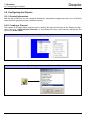
The creation of those channels is done as described in chapter 2.1.5.1 on page 4 by insertion of the
„Dupline Channel“ object. Then configure the channel by proceeding in the following steps:
2.1.6.1 Digital Channels (Switching/Shutter Channels)
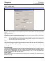
1. For the type of representation select <Digital value> on page <Basic Settings>.
2. In field <Dupline Address> set the address of the channel to be displayed.
3. Specify the function:
– Select <Switching channel> for push-button, toggle functions or similar.
– Select <Shutter/ Shutter Master> if it is a shutter control or a shutter master control.
With this setting DRTconf will automatically block the next channel, as both the Up
and Down channels are operated under the uneven address.
– You should therefore answer "OK" to the question asking whether the next channel is
to be deleted.
4. If the digital channel is to be operational then tick the <Unlocked> option as operation type.
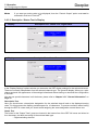
5. Now switch to the page <Display Settings>.
6. Now enter the <Descriptive Text> which is to be displayed. The embedded display shows
how the text will look.
7. Then specify the <Status Text> for the channel status:
– In the case of switching channels this is normally "On" or "Off"; with shutter control
objects it is "Up" or "Down".
– Tip: By activating the <Default> button the above data will be set automatically.
8. Finished!
2.1.6.2 Analog Channels
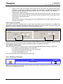
1. In the case of an analog channel (temperature or light level sensor) select <AnaLink Value>
as the type of representation.
2. Specify the function as follows:
– Enter the minimum and maximum values in the <Sensor Input Range> boxes;
– Select <Light Level Function> if it concerns the analog value of a DLUX (in which
case the light level range will automatically be set).
3. Now switch to the page <Display Settings>.
4. Now enter the <Descriptive Text> to be displayed. The embedded display shows you how
the text will look.
5. Then specify in the <Status Text> box the unit to be displayed:
– With analog data this is normally either "ºC" or "Lux".
– Tip: By activating the <Default> button the above data will be set automatically.
6. Finished!
2.1.7 Transferring the Configuration
Once all required channels have been configured the complete application can be transferred:
1. Proceed via the <Options><Communication> to switch on the PC connection (COM port),
which is linked to the DRT 2 via the DKK 1 serial cable.
DRTconf User Manual
Novmber 2009, Version 1.40
Page 8