1
User’s Manual
Matrix 100 Switcher
Contents
Chapter 1 - Introduction to Matrix 100
General .......................................................................................................................... 1-1
I/O Modules ................................................................................................................... 1-1
Configurations ................................................................................................................ 1-1
Standard Features ......................................................................................................... 1-2
Optional Features .......................................................................................................... 1-3
Sample Configuration .................................................................................................... 1-4
Specifications ................................................................................................................. 1-5
Illustrations:
Figure 1-1. Rear view of a fully-populated Matrix Switcher ............................................ 1-2
Figure 1-2. Matrix 100 Front Panel ................................................................................. 1-3
Figure 1-3. Block diagram of a Matrix 100 ...................................................................... 1-4
Chapter 2 - Rear Panel Connections
Multi-Output Connection ................................................................................................ 2-1
Genlock Connections ..................................................................................................... 2-2
RGB Input Connections ................................................................................................. 2-2
RGB Connections with Right & Left Audio ..................................................................... 2-3
RGBS Connections with Right & Left Audio ................................................................... 2-4
RGBHV Connections with Right & Left Audio ................................................................ 2-5
Composite Video Connections ....................................................................................... 2-6
S-Video Connections ..................................................................................................... 2-7
Audio Terminal Connections ........................................................................................... 2-9
Illustrations:
Figure 2-1. Matrix 100 Switcher and Input/Output Devices ............................................ 2-1
Figure 2-2. Genlock connects to a timing source ........................................................... 2-2
Figure 2-3. An example of RGB, or Component Video ................................................... 2-3
Figure 2-4. An example of RGBS, 4-BNC, or Composite Sync Video ............................. 2-4
Figure 2-5. An example of RGBHV, 5-BNC, or Video with Separate (H and V) Sync ...... 2-5
Figure 2-6. Composite Video with Right & Left Audio ..................................................... 2-6
Figure 2-7. S-Video Connections with Right & Left Audio .............................................. 2-8
Figure 2-8. Audio Connectors with Captive Screws (above and right) ............................ 2-9
Figure 2-9. Typical Audio Cable Connectors ................................................................... 2-9
Figure 2-10. Three ways to wire the Input and Output Audio Connectors ....................... 2-9
Chapter 3 - Using the Front Panel Controller
QuickSwitch Front Panel Controller (QS-FPC) Operation .............................................. 3-1
Input and Output Buttons .................................................................................. 3-1
I/O Module Select Buttons ................................................................................ 3-2
Control Buttons ................................................................................................. 3-2
Example #1: Configuring the Ties for Input 2 ..................................................... 3-3
Example #2: Display Ties for Input 5 ................................................................. 3-3
Ties, Configurations and Presets ................................................................................... 3-4
Examples .......................................................................................................... 3-4
Worksheets .................................................................................................................... 3-5
Illustrations:
Figure 3-1. Matrix 100 Front Panel ................................................................................. 3-1
Figure 3-2. Matrix 100 Power Switch .............................................................................. 3-1
Figure 3-3. Input/Output Buttons and LEDs ................................................................... 3-1
Extron • Matrix 100 • User’s Manual
i
Contents
Chapter 4 - Hardware Installation
IEC Power Panel ............................................................................................................ 4-1
Standard Power Supply ..................................................................................... 4-1
Redundant Power Supply (optional) .................................................................. 4-1
QuickSwitch Front Panel Controller ................................................................... 4-1
Removing the Matrix 100 Cover ..................................................................................... 4-2
Changing Matrix Front Panels ........................................................................................ 4-2
Replacing a Blank Panel with a QuickSwitch Front Panel Controller ................. 4-3
Replacing the Lithium Battery ........................................................................................ 4-3
Changing the Main Fuse ................................................................................................ 4-4
RS-232/RS-422 Communications .................................................................................. 4-4
9-Pin Communication Connector ...................................................................... 4-4
RS-232 Protocol ................................................................................................ 4-4
Installing a Redundant Power Supply ............................................................................. 4-5
Adding an Audio Module ................................................................................................ 4-6
Installing I/O Modules in the Rear Panel ........................................................................ 4-9
Installing QS-FPC Software Update ........................................................................... 4-11
Illustrations:
Figure 4-1. IEC Power Panel: Power Switch, Fuse and Power Connectors .................... 4-1
Figure 4-2. Matrix 100 Cover has six screws ................................................................. 4-2
Figure 4-3. Front Panel Cable Connections and Battery Location .................................. 4-3
Figure 4-4. Matrix 100, Face-up ..................................................................................... 4-3
Figure 4-5. Wiring the RJ45 Cable ................................................................................. 4-3
Figure 4-6. Changing the Fuse ...................................................................................... 4-4
Figure 4-7. Swapping the RS-232/RS-422 Port cable .................................................... 4-4
Figure 4-8. Matrix 100 Comm Connector ....................................................................... 4-4
Figure 4-9. Connecting the Redundant Power Supply and Ground Wire
Connections (Right detail) ............................................................................ 4-5
Figure 4-10. Redundant Power Supply Connector ......................................................... 4-5
Figure 4-11. How the Audio Module fits in the Matrix ..................................................... 4-6
Figure 4-12. Audio Module connections and hardware .................................................. 4-6
Figure 4-13. The Matrix Audio Module before installation ............................................... 4-7
Figure 4-14. Lift the Back Panel slightly and slip the Audio Module under it ................... 4-7
Figure 4-15. Secure the module in position .................................................................... 4-7
Figure 4-16. Plug the Ribbon Cables from each module to the Main Controller board ... 4-8
Figure 4-17. This illustration shows the modules already installed ................................. 4-9
Figure 4-18. Squeeze the tabs to release the plug ......................................................... 4-9
Figure 4-19. Module differences ................................................................................... 4-10
Figure 4-20. DIP Switch operation ............................................................................... 4-10
Figure 4-21. DIP Switch settings for each module ........................................................ 4-10
Figure 4-22. MRAM Module ......................................................................................... 4-10
Figure 4-23. Remove the Front Panel to access the Software IC Chip ......................... 4-11
Figure 4-24. Use the PLCC Chip Puller to remove the Software IC Chip ..................... 4-11
Chapter 5 - Windows® Control Software
Extron Matrix Control Software ...................................................................................... 5-1
Windows Example ......................................................................................................... 5-1
Matrix 100/200 Help ....................................................................................................... 5-3
Illustrations:
Figure 5-1. Extron Windows Group Example ................................................................. 5-1
Figure 5-2. Control Program Example ............................................................................ 5-2
Figure 5-3. Configured Matrix Example .......................................................................... 5-2
Figure 5-4. Example of the Help Menu ........................................................................... 5-3
ii
Extron • Matrix 100 • User’s Manual
Contents
Appendix A - RS-232 Programmer’s Guide
Control Ports .................................................................................................................. A-1
QS-FPC Ports ................................................................................................... A-1
Host/Matrix Data Format ................................................................................................ A-1
Binary/hex/decimal Conversion Table ................................................................ A-2
Command Structure ....................................................................................................... A-2
Command Specifier, Data, End of Transmission ................................................ A-2
Host-Initiated Communications Protocol ........................................................................ A-3
Error Codes (Erc) .............................................................................................. A-3
Matrix-Initiated Communications Protocol ...................................................................... A-4
Timing ............................................................................................................... A-4
Command List (Host-to-Matrix) ......................................................................... A-4
Reports (Matrix-to-Host), Communication Control ............................................ A-4
Using Commands .......................................................................................................... A-5
CMD0 (30h) - Send Status ................................................................................ A-5
CMD1 (31h) - Report ID .................................................................................... A-6
CMD2 (32h) - Turn Power On ............................................................................ A-7
CMD3 (33h) - Turn Power Off ............................................................................ A-7
CMD4 (34h) - Send Software Version ............................................................... A-7
Set (Tie) Connection Commands ...................................................................... A-8
Planes and Plane Maps .................................................................................... A-8
CMD5 (35h) - Set (Tie) Connection ................................................................... A-9
CMD7 (37h) - Set (Tie) All Connections ............................................................ A-9
CMD8 (38h) - Download Status and Presets .................................................. A-10
CMD9 (39h) - Mute All Planes ......................................................................... A-10
CMD10 (3Ah) - Save Current as Preset # ....................................................... A-10
CMD11 (3Bh) - Load Preset # ......................................................................... A-10
CMD12 (3Ch) - Mute Selected Outputs .......................................................... A-11
CMD13 (3Dh) - Request Mute Map ................................................................. A-11
CMD25 (49h) - Set RGB Delay ....................................................................... A-12
CMD26 (4Ah) - Request RGB Delay Information ............................................ A-12
Reports (Matrix-to-Host) .............................................................................................. A-13
Report0 (70h) - Status .................................................................................... A-13
Report1 (71h) - New Controlling Port .............................................................. A-13
Appendix B - Part Numbers and Reference
Related Part Numbers ................................................................................................... B-1
Option Kit Part Numbers ................................................................................... B-1
BNC-4 Cables (High Resolution BNC Cables) .................................................. B-2
Matrix 100 Part Numbering System ............................................................................... B-3
Manual number and status
68-199-01, Rev B
69-12
Extron • Matrix 100 • User’s Manual
iii
Contents
The following icons may be used in this manual:
_________ Important information — for example, an action or a step that must be done
before proceeding.
_________ A Warning — possible dangerous voltage present.
_________ A Warning — possible damage could occur.
_______ A Note, a Hint, or a Tip that may be helpful.
________ Possible Electrostatic Discharge (ESD) damage could result from touching
electronic components.
________ Indicates word definitions. Additional information may be referenced in another
section, or in another document.
iv
Extron • Matrix 100 • User’s Manual
Matrix 100
User’s Manual
1
Chapter One
Introduction to Matrix 100
I/O Modules
Configurations
Standard Features
Optional Features
Matrix 100 Module Specifications
Extron • Matrix 100 • User’s Manual
Chapter 1 • Introduction to Matrix 100
General
Each Extron Matrix 100 is custom designed to the user’s specifications. The
configuration is built from various combinations of ten I/O modules. The I/O
modules and possible configurations are listed below. The Matrix 100 can be
controlled from a host computer or from a QuickSwitch Front Panel Controller
(QS-FPC).
Matrix units can also be interconnected to expand the switching capabilities for
up to 48 inputs by 48 outputs. This allows for multiple switching combinations.
I/O Modules
Matrix 100 Switchers are ordered for a specific application with a combination of
I/O modules. Each module switches one type of video signal – one for red, one
for blue, etc. One audio module switches both left and right stereo channels.
•
•
•
•
•
•
•
•
•
•
4 x 4 Medium-Resolution Analog Module (MRAM), 175 MHz video bandwidth
8 x 4 Medium-Resolution Analog Module (MRAM), 175 MHz video bandwidth
8 x 8 Medium-Resolution Analog Module (MRAM), 175 MHz video bandwidth
4 x 4 Sync Module
8 x 4 Sync Module
8 x 8 Sync Module
4 x 4 Video Module
8 x 4 Video Module
8 x 8 Video Module
8 x 8 Stereo Audio Module
For example: a Matrix 100 designed to switch RGB, separate horizontal and
vertical sync, and stereo audio will require the following modules: three MRAM,
two Sync and one audio modules.
Configurations
Depending upon the configuration of I/O modules (above), the Matrix 100
Switcher can have up to 16 different input/output configurations. The
configuration determines how many modules are required.
•
•
•
•
•
•
•
•
•
•
•
•
•
•
•
•
1-1
RGsB – Red, Green, (sync on green), Blue
RGBS – Red, Green, Blue and separate composite Sync
RGBHV – Red, Green, Blue and separate H&V Sync
RGsBCv – Red, Green, (sync on green), Blue, and Composite video
RGsBYC – Red, Green, (sync on green), Blue and S-Video
RGBSCv – Red, Green, Blue, composite Sync, and Composite video
RGsBA – Red, Green, (sync on green), Blue, and Audio
RGBSA – Red, Green, Blue, Sync, and Audio
RGBHVA – Red, Green, Blue, separate H&V sync, and Audio
RGsBCvA – Red, Green, (sync on green), Blue, Composite video, and Audio
RGsBYCA – Red, Green, (sync on green), Blue, S-Video, & stereo Audio
RGBSCvA – Red, Green, Blue, composite Sync, Composite video, and Audio
CvA – Composite video, and Audio
YCA – S-Video with Audio
Cv – Composite video
YC – S-Video
Extron • Matrix 100 • User’s Manual
Chapter 1 • Introduction to Matrix 100
Standard Features
•
•
•
•
•
•
Microprocessor control, with battery backup
RS-232 control
RGBS, Video, Audio Breakaway
Composite and S-Video Genlock
RGB video delay switching (via RS-232/RS-422)
175 MHz bandwidth.
Microprocessor Control The Matrix 100 is programmable from a host system, or from the optional
QuickSwitch Front Panel Controller. It uses memory to store up to eight preset
configurations. The battery backup prevents loss of preset information.
RS-232 Control
The Matrix 100 can be controlled by any remote control system or computer with
serial communications capability. Refer to Appendix A for programming
guidelines including a complete listing of RS-232 commands and protocol.
Breakaway
The RGBS, Video, Audio Breakaway feature of the Matrix 100 allows the user to
program any Video, S-Video or Audio Channel to be controlled separately
(breakaway), or as a group (follow one or more inputs, or all RGB inputs). A fully
populated RGBS composite video and audio switcher can be controlled as three
separate switchers.
Breakaway provides individual video or audio outputs to follow any one or more
RGBS inputs when switched to an output channel. This makes the Matrix 100
capable of adding audio to any or all RGBS or video channels, as well as
switchable video and audio to follow any switched RGBS channel.
Video Genlock
The Matrix 100 features a broadcast quality NTSC/PAL/SECAM Composite
Video or S-Video Genlock for synchronized switching of signals. The Matrix 100
will Genlock as many composite video signals as are installed in the switcher.
RGB Delay Switching The Matrix 100 can be programmed (via RS-232) to delay switching the RGB
video for 1 to 9 seconds after the sync is switched. This allows the display device
to be in sync before the picture arrives, providing seamless switching of the
RGBS signals when switching between various frequencies.
175 MHz Bandwidth
Even when fully populated, the Matrix 100 has a bandwidth of no less than 175
MHz (-3 dB).
Figure 1-1. Rear view of a fully-populated Matrix 100 Switcher
Extron • Matrix 100 • User’s Manual
1-2
Chapter 1 • Introduction to Matrix 100
Optional Features
• QuickSwitch™ Front Panel Controller (QS-FPC)
• Redundant power supply
• SmartControl™ microprocessor
Figure 1-2. Matrix 100 Front panel
QuickSwitch™ Front Panel Controller (QS-FPC)
The QuickSwitch Front Panel Controller (QS-FPC) provides local control of all
Matrix 100 Switcher functions. It is supplied as an optional accessory to the
Matrix 100 and is intended for users who wish to supplement normal RS-232
computer control with local or remote operator control. Refer to Chapter 2 for
instructions for mounting the QS-FPC, and to Chapter 4 for operation. The
QS-FPC includes the following features:
Control Microprocessor SmartControlTM is the Front Panel’s built-in
microprocessor. With it, the user determines the Matrix 100 input/output
configuration, what presets are saved, as well as all other switcher settings.
Configuration Memory SmartControl can store up to eight different matrix
configurations (called presets). This can save hours of reprogramming each I/O
configuration. The QuickSwitch Front Panel Controller (QS-FPC) allows for easy
configuration of inputs and outputs, as well as the control of additional system
features.
QuickSwitch SmartControl The Front Panel includes full complement of function
buttons make setup and programming the unit fast and easy.
Redundant Power Supply
The Matrix 100 can be ordered with an optional redundant (backup) power
supply to prevent signal loss if input power to the primary power supply should
suddenly be lost or interrupted.
1-3
Extron • Matrix 100 • User’s Manual
Chapter 1 • Introduction to Matrix 100
Sample Configuration
Figure 1-3 shows one example of the I/O modules that could be installed in six
planes of a Matrix 100. See page 1-1 for I/O modules and possible
configurations.
For example, an 8 x 8 RGBS switcher requires: three 8 x 8 medium-resolution
analog modules (MRAM) and one 8 x 8 sync module (Syn). This would occupy
the Red, Green, Blue and one Sync/Video planes. The fifth plane could have a
composite video module (Cv), and the sixth plane could have an audio switching
module (Aud).
This configuration is capable of being
controlled and routed as three
separate switchers:
• one 8 x 8 RGBS matrix switcher
• one 8 x 8 video switcher
• one 8 x 8 audio switcher
In addition, SmartControl™ allows
the Matrix 100 to group these
functions as a single RGBS
composite video switcher with stereo
audio.
The bottom of the diagram illustrates
how the Main Controller (and the
optional QuickSwitch Front Panel
Controller) routes the various inputs
to the outputs.
Figure 1-3. Block diagram of a Matrix 100
Extron • Matrix 100 • User’s Manual
1-4
Chapter 1 • Introduction to Matrix 100
Matrix 100 I/O Module Specifications
Power .
Dimensions .
Shipping Weight .
Operating Temperature .
Storage Temperature .
MTBF .
Approved .
Warranty .
90 - 260 VAC, 50/60 Hz, 60 Watts
17" W, 15" D, 6.8" H
22 lbs (10 kg)
0° C - 50° C
-20°C - 70° C
35,000 Hours (demonstrated)
UL Listed
2 years parts and labor
MRAM Video (Medium Resolution Analog Module)
Connectors . BNC
Bandwidth . 175 MHz (-3 dB)
Crosstalk:
at 10 MHz . -50 dB(typical) See note 1.
at 100 MHz . -30 dB
Note 1: Crosstalk is the
attenuation of all hostile
signals relative to a given
input-output connection.
Note 2: Isolation is the
attenuation of an input signal
relative to an un-selected
output when all inputs have
the same signal applied
simultaneously.
Isolation:
at 10 MHz . -60 dB (typical) See note 2.
at 100 MHz . -55dB
Return Loss:
at 10 MHz . -20 dB
Input Impedance .
Output Impedance .
Switching Speed .
Input Signal .
Gain .
75 ohms
75 ohms
200 ns (nominal)
0.3-1.0 V p-p (max dc offset ± 0.30 V)
Unity ±1%
Composite Video Module
Frequency Response . -0.5 dB @ 5 MHz; -3.0 dB @ 15 MHz
Differential Gain . 0.5%
Differential Phase . 1.3°
Line and Field Tilt . Less than 0.1%
Isolation between outputs Greater than 40 dB @ 5 MHz
Crosstalk . Greater than 40 dB @ 5 MHz
CMRR . -60 dB
Propagation Delay . 10ns
Input Signal . 75 ohms, analog, 0-1.0 V p-p
. (max dc offset ±0.30 V)
Gain . Unity
Sync Module
Input Impedance .
Output Impedance .
Max. Input Voltage .
Input Sensitivity .
Output Level .
.
Max. Propagation Delay .
Max. Rise/Fall Time .
Polarity .
1-5
510 ohms
75 ohms
±5 V
500 mV p-p
4.5 V p-p not terminated;
2.2 V p-p terminated at 75 ohms
64ns H to L (41 ns L to H)
8 ns H to L (3.6 ns H to L)
Follows input
Extron • Matrix 100 • User’s Manual
Chapter 1 • Introduction to Matrix 100
Audio Module, General
Input Impedance . High Z (>10k ý, typical)
Input Voltage Level . To 6 V p-p into 600 ý
Output Impedance . Low, capable of driving 600 ý, balanced
Output Level . Unity gain
Connectors . 6-conductor, Captive Screw Audio Terminal
Signal to noise . Better than 110 dB, 20Hz-20kHz
Total Harmonic Distortion + Noise
Worst case . 0.03% @ 20kHz, 30 V p-p
. (Differential Output)
Adjacent Channel Crosstalk
Better than -85 dB @ 20kHz
Common Mode Rejection Ratio -55 dB worst case @ 20kHz (-65 dB Typical)
Stereo Channel Separation
Greater than 60 dB 20 Hz - 20kHz
Bandwidth . 20Hz - 20kHz, Flat ± 0.1 dB
Audio Input Specifications
Maximum Input Level . 45 V p-p Differential
. 22 V p-p Single-ended
Nominal Input Program Level:
-10 dBu (300 mV rms)
Input Impedance . 20 k ý, Differential
. 10k ý, Single-ended
Audio Output Specifications
Maximum Output Level: . 45V p-p Differential
. 22 V p-p Single-ended
Nominal Output Program Level:
Professional Mode . +4 dBu (1.2 V rms)
Consumer Mode . -10 dBu (300 mV rms)
Output Impedance . 50 ý, Differential to Ground
Extron • Matrix 100 • User’s Manual
1-6
Chapter 1 • Introduction to Matrix 100
Notes:
1-7
Extron • Matrix 100 • User’s Manual
Matrix 100 Switcher
User’s Manual
2
Chapter Two
Rear Panel Connections
Multiple Output Connections
Genlock Connections
RGB Input Connections
Composite Video Input Connections
S-Video Input Connections
Audio Terminal Connections
Chapter 2 • Rear Panel Connections
Multi-Output Connection
When using the Matrix 100 to switch different types of video signals, the signal
output from the switcher is in the same format as the input.
• RGB and Sync (composite or separate H&V) signals will pass through the RGB
and Sync outputs
• NTSC and PAL video signals will pass through the composite video output
• S-Video will pass through the S-Video output (two Video modules)
Therefore, if multiple signal types are used in the same switcher, those same
signals will be available to the output devices.
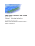
In the diagram below, the Matrix 100 supplies RGB output for large screen
projectors and data monitors, composite video output for LCD projector and
audio output for a stereo audio system.
Figure 2-1. Matrix 100 Switcher and Input/Output Devices
2-1
Extron • Matrix 100 • User’s Manual
Chapter 2 • Rear Panel Connections
Genlock Connections
If so desired, the Matrix 100
can use an external
Genlock signal to
synchronize composite
video or S-Video switching.
The illustration here shows
the Genlock connections.
The In connector goes to a
timing source. The Out
connector allows the signal
to be passed on to another
video device; it does not
have to be connected for
Matrix operation.
Figure 2-2. Genlock connects to a timing source.
RGB Input Connections
All RGB input and output connections to the Matrix 100 are made with BNC type
connectors. Many types of RGB output devices (scan doublers, document
cameras, etc.), including most computers, do not have BNC video output
connectors. If not, a suitable adapter, or an Extron computer-video interface,
should be used to adapt the device output to the BNC input of the Matrix 100.
With the proper adapter, the RGB and Sync signals can be connected directly to
the R, G, B, H, V inputs of the switcher. If the RGB signal is using the Sync-onGreen channel, connect the RGB cables to the switcher without using the sync
channels.
RGB input connections to the Matrix 100 can be made using the following
combinations:
Without Audio
RGsB - Red, Sync-on-Green, Blue
RGBS - Red, Green, Blue, and Composite Sync
RGBHV - Red, Green, Blue, H&V Sync
With Audio
RGsB with R&L Audio - Red, Green, Blue, and Audio Follow
RGBS with R&L Audio - Red, Green, Blue, Sync and Audio Follow
RGBHV with R&L Audio - Red, Green, Blue, H&V Sync and Audio Follow
The following pages illustrate examples for the above combinations with Right
and Left Audio connections. If audio is not being used, ignore that part.
Extron • Matrix 100 • User’s Manual
2-2
Chapter 2 • Rear Panel Connections
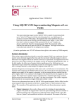
RGB Connections, with Right & Left Audio
Figure 2-3 illustrates the Matrix 100 connections for switching RGB, or
component video. Choose an input number and connect each cable from the
source to the appropriate input on the Matrix 100. (The example shows
Input #1.) Likewise, choose an output number and connect each of the three
cables to a destination device.
3
1
2
4
3
Figure 2-3. An example of RGB, or Component Video
_______ Audio Connections may or may not be used. See page 2-9 for wiring.
2-3
Extron • Matrix 100 • User’s Manual
Chapter 2 • Rear Panel Connections
RGBS Connections with Right & Left Audio
Figure 2-4 illustrates the Matrix 100 connections for switching RGBS, or video
with composite sync. Choose an input number and connect each of the four
cables from the source to the appropriate input on the Matrix 100. (The example
shows Input #2.) Likewise, choose an output number and connect each of the
four cables to a destination device.
3
1
2
4
3
Figure 2-4. An example of RGBS, 4-BNC, or Composite Sync Video
_______ Audio Connections may or may not be used. See page 2-9 for wiring.
Extron • Matrix 100 • User’s Manual
2-4
Chapter 2 • Rear Panel Connections
RGBHV Connections with Right & Left Audio
Figure 2-5 illustrates the Matrix 100 connections for switching RGBHV, or video
with separate sync. Choose an input number and connect each of the five
cables from the source to the appropriate input on the Matrix 100. (This example
shows Input #2.) Likewise, choose an output number and connect each of the
five cables to a destination device.
3
1
2
4
3
Figure 2-5. An example of RGBHV, 5-BNC, or Video with Separate (H and V) Sync
_______ Audio Connections may or may not be used. See page 2-9 for wiring.
2-5
Extron • Matrix 100 • User’s Manual
Chapter 2 • Rear Panel Connections
Composite Video Connections
NTSC and PAL are television or VCR type signals on a single coax cable, which
may or may not have stereo audio. For this application, the Matrix 100 uses one
Composite Video module, shown in Figure 2-6 in the right-most position.
Connect the output of an NTSC/PAL video source to a Video module input. (See
illustration below.) Connect the video output from the Matrix to a destination
device that uses Composite Video.
________ NTSC - National Television Standards Committee
PAL - Phase Alternation Line
3
1
2
4
3
Figure 2-6. Composite Video with Right & Left Audio
_______ Audio Connections may or may not be used. See page 2-9 for wiring.
Extron • Matrix 100 • User’s Manual
2-6
Chapter 2 • Rear Panel Connections
S-Video Connections
S-Video (S-VHS) is typically the output from the AV source on a 4-pin miniature
din-type connector and must be converted to 2 BNC type connectors - one for
Chrominance (C) and the other for Luminance (Y).
_______ To adapt S-VHS to BNC, use Extron cable 26-353-01.
To connect S-Video to the Matrix 100, the Matrix must be ordered with two
composite video modules. Use one for Luminance (Y) and the other for
Chrominance (C). The Y and C signal lines are then connected to the two video
modules. See illustration on facing page.
_______ When connecting Y and C cables, be sure to use the same input numbers on
the two video modules for each source. This example uses number 2 inputs.
Also use the same output number pair for each destination. This example uses
number 2 outputs, but we could have used outputs number 1, or 3, etc.
Input Connections
Choose which input number to use to connect the S-Video source device to the
Matrix 100. Connect the Luminance (Y) to the input connector on the first (left)
Video module and the Chrominance (C) to the same input number on the
second (right) Video module.
If audio is used, connect the right and left audio source outputs to the right and
left inputs on the back of the Matrix 100. See page 2-9 for details on audio
connections.
Output Connections
Choose which Matrix 100 output number to use for the S-Video destination unit.
Connect the Luminance (Y) output from the first (left) Video module to the
Luminance input of the destination unit. Connect the Chrominance (C) from the
same output number on the second (right) Video module to the Chrominance
input of the Video destination unit.
If audio is used, connect the right and left audio output from the Matrix
connector to the right and left inputs of the audio destination unit. See page 2-9
for details on audio connections.
_______ A Matrix 100 can be configured with RGsB (sync on green) and S-Video.
2-7
Extron • Matrix 100 • User’s Manual
Chapter 2 • Rear Panel Connections
3
1
2
4
3
Figure 2-7. S-Video Connections with Right & Left Audio
_______ Audio Connections may or may not be used. See page 2-9 for wiring.
Extron • Matrix 100 • User’s Manual
2-8
Chapter 2 • Rear Panel Connections
Audio Terminal Connections
The rear of the Matrix 100 has two rows (16 sets) of audio connector pins, below
the BNC connectors. The top row is for 8 inputs, and the bottom for 8 outputs.
Each group of six pins accommodates a left and a right audio channel. One
sample is shown here.
The 6-terminal audio connectors are supplied with the switcher. The connectors
are wired to the audio cables, using the captive screws inside the connectors.
The connectors are then plugged into the appropriate position in the audio
terminal strip on the rear panel. The audio area of the back panel is labeled "R"
(right) and "L" (left) for each channel.
When wiring the connectors and inserting them into the Matrix 100
switcher, the screw heads (see illustration right) must face down.
Figure 2-8. Audio Connectors with Captive Screws (above and right)
Audio Wiring Applications
Three methods of wiring the connectors for input and output are listed here, and
illustrated below. The connector screws do not show in the picture because they
are on the other side.
Tip
Sleeve
Tip (+)
Ring (-)
Ring (-)
· Unbalanced High Impedance (High Z) Stereo Tip, Ring, Ground (Left & Right)
· Balanced High Impedance (High Z) Stereo Tip, Ring (Left & Right)
Sleeve
· Balanced 600 ý input Impedance Stereo Tip, Ring (Left & Right)
Figure 2-9. Typical Audio Cable Connectors
_________ If using unbalanced audio output, use lower-left connector as an example, and
connect the sleeve to Gnd. Connecting it to the negative (-) terminal will damage
audio output circuits.
_______ Use captive-screw audio connectors, Extron part number 10-163-01
Figure 2-10. Three ways to wire the Input and Output Audio Connectors
2-9
Extron • Matrix 100 • User’s Manual
Matrix 100
User’s Manual
3
Chapter Three
Using the Front Panel Controller
I/O Module Select
Input and Output Buttons
Control Buttons
Operating Examples
Configuration Worksheets
Chapter 3 • Using the Front Panel
QuickSwitch™ Front Panel Controller (QS-FPC) Operation
The QuickSwitch Front Panel Controller (Figure 3-1) has its controls arranged in
two areas. The left side is Input and Output buttons, and the right side is Control
buttons and I/O Module Select buttons.
The basic operation of this panel is that it allows the user to tie any one input to
one or more outputs. (An output can never be tied to more than one input.)
Thus, each input may have a tie (one output), or a “set of ties” (more than one
output). At any one time, the active configuration of a Matrix 100 may have a set
of ties per each available input. Any configuration (sets of ties) may be stored as
a Preset. The maximum number of Presets is eight. The Matrix 100 has Battery
Backup; Presets remain saved when power is off.
_______ Because each Matrix 100 is custom-built, it may have different combinations of
Input/Output (I/O) modules. For this reason, the operation of your unit will vary
to reflect these differences. See page A-3 for information on how each unit is
built. The QS-FPC (Front Panel) is also an option.
Figure 3-1. Matrix 100 Front Panel
Power On Switch and LED
Before using the Matrix 100 front panel, turn power
on with the Power Switch on the back of the unit
(shown right). The red LED on the left end of the
front panel (shown left) lights when power is on.
Figure 3-2. Matrix 100 Power Switch
Input and Output Buttons
The panel has a button and an LED for each input and each output. If the matrix
is 4x4, only the four left input and output buttons and LEDs will operate. If the
matrix is 8x4, all eight input buttons will operate, but only the four left output
buttons and LEDs will operate. The best way to describe the Input and Output
buttons is to use them in real examples with the other panel buttons. This is
done on the pages
that follow.
_______ Each input button and
LED also refers to a
Preset number.
Presets are discussed
on the next page.
Figure 3-3. Input/Output Buttons and LEDs
3-1
Extron • Matrix 100 • User’s Manual
Chapter 3 • Using the Front Panel
I/O Module Select Buttons
The four buttons on the far right side of the panel are used to select the I/O
modules to be viewed or configured. The buttons and LEDs will not operate if
the corresponding modules are not installed in your Matrix 100. For example, if
your unit does not have audio, the AUD buttons and LEDs will not operate.
When an I/O button is pressed, the associated LED for that I/O module will light
to show that it is active. This “active” state remains in effect until that button is
pressed again and the LED goes out – or power is removed. These buttons may
be used independently or in combinations. For example, if you want to view or
configure both RGBS and Audio (audio follow), press RGBS and AUD 1.
RGBS Button – This button selects the I/O modules for Red, Green, Blue and
Sync modules to be viewed or configured. Here are some examples:
• If your unit has RGsB (no separate sync), the RGBS button operates on the
Red, Green and Blue signals.
• If your unit has RGB with composite sync, the button operates on the Red,
Green, Blue and Sync signals.
• If your unit has RGBH and V (separate sync), the button operates on the Red,
Green, Blue, Horizontal Sync and Vertical signals.
With RGBS active, switching configurations for RGB and Sync may be viewed or
set up by pressing Input and Output buttons. See example on the next page.
Video Button – If the matrix has Composite Video, or S-Video, press this button to
view or configure those signals.
AUD 1 Button – If the matrix has an audio module, this button allows Audio to be
configured or viewed.
AUD 2 Button – This button is reserved for future use.
Control Buttons
Enter Button – This button is used to save changes when setting up a
configuration. To set up a configuration, press the desired Input button, press
the desired Output button(s), and then press Enter. See examples on next page.
ESC Button – The Escape button is used to end an operation and reset all of panel
LEDs for Inputs, Outputs and Controls (active I/O Module LEDs remain on).
The ESC button does not reset any configurations that have been entered.
Preset – All current (active) configurations in the Matrix 100 may be stored as a
Preset. To do this, press Preset twice (or hold the button for two seconds) and
the Preset LED will blink. While the preset LED is blinking, press the Input
button for the Preset number to be stored. The LED for that Input will light
briefly, and then both the Input LED and the Preset LED will go out. (No output
buttons will light.) The Preset has now been stored. There can be one preset for
each Input button, for a total of eight – regardless of the number of available
inputs or outputs.
_________ The Input buttons and LEDs have two independent functions – as Input
numbers and as Preset numbers. When using them to store or load a Preset,
this has nothing to do with which inputs are switched to which outputs.
To load a preset that has been stored, press Preset once (briefly). The LED will
light steady (not blinking). Press the Input button for the desired Preset number.
That LED will light briefly, and then both it and the Preset LED will go out.
With Presets stored, the Matrix 100 can be configured again without affecting
the stored Presets. This means that there can be eight matrix configurations
stored as Presets, and a ninth one active. However, when a Preset is loaded, it
destroys the active configuration.
Extron • Matrix 100 • User’s Manual
3-2
Chapter 3 • Using the Front Panel
View – Pressing the View button lights its LED for to indicate a “view-only” mode to
allow the display of the current Matrix 100 configurations. In this mode, pressing
any input or output button will also light all LEDs for the input and output(s) that
are part of that configuration. Pressing a button for any unassigned output will
light all of the unassigned outputs.
_______ Using the View mode prevents changing configurations by accident.
Pages 3-4 and 3-5 have examples of Presets.
Example #1: Configuring the Ties for Input 2.
If necessary, press ESC to clear all Input,
Output and Control LEDs.
○
○
○
○
○
○
Example #2: Display the Ties for Input 5.
See picture, lower left.
○
○
○
If an output had been tied to
another input, that tie will be
broken in favor of the new one.
○
Preset – A configuration that has
been stored.
_______
4. Press Enter to complete the
operation.
○
Active Configuration – The
configuration that is currently
being used by the Matrix 100.
3. Select the Output(s) to be tied to the
chosen Input. The Output LEDs will
blink to indicate the tentative
changes. (Example shows
Outputs 2 and 5.)
○
Configuration – Any Tie, Set of
Ties, or Sets of Ties between
Input(s) and Output(s).
2. Select the Input number. (Example
shows Input 2.)
○
Set of Ties – More than one
connection between one Input and
more than one Output.
○
Tie – A connection between an
Input and an Output.
1. Select I/O modules to be switched.
(Example shows RGBS and Audio.)
If necessary, press ESC to clear Input,
Output and Control LEDs.
1.
Select I/O modules to be switched (example shows RGBS).
2. Select the Input number (example shows Input 5).
The LED(s) for the Outputs (numbers 3, 4 and 7) will light to show
that they are connected to Input 5.
If an I/O module LED blinks when displaying ties, it means that the
ties for that module are not the same as those for the RGBS module.
3.
3-3
Press ESC to clear all Input, Output and Control LEDs.
Extron • Matrix 100 • User’s Manual
Chapter 3 • Using the Front Panel
Ties, Configurations and Presets
Only one configuration may be active at one time, and only one Tie (or set of
Ties) may be viewed at one time. Therefore, the only way to view each of the
stored Presets is to load (activate) each preset and then view each set of Ties in
that configuration (as shown in Example #2).
Example #3
This example shows a
configuration with seven Ties, or
sets of Ties. RGBS and Audio
are shown as separate lines.
Matrix 200 (8x8) Preset example
Example #4
This configuration shows a an
8x4 matrix with four sets of Ties.
RGBS and Audio are shown as
separate lines.
Matrix 200 (8x4) Preset example
_______ Rather than try to remember the configuration for each preset, worksheets may
be used to record this information. Make copies of the worksheets are provided
on the next page and use one for each Preset configuration.
Example #5
This configuration was stored as
Preset 7. It has one set of Ties
for Input 8. Because it was
stored to do test patterns, only
RGBS is tied to the Video Test
Generator source.
When diagramming for more
than one I/O module, use
different colors for each I/O
module.
For our own records, we chose
the title “Test Patterns”.
Because the matrix is 8x4,
outputs 5 - 8 have been crossed
out for this example.
Extron • Matrix 100 • User’s Manual
Matrix 200 Configuration Worksheet
3-4
Chapter 3 • Using the Front Panel
Matrix 200 Configuration Worksheet
Matrix 200 Configuration Worksheet
3-5
Extron • Matrix 100 • User’s Manual
Matrix 100 Switcher
User’s Manual
4
Chapter Four
Hardware Installation
IEC Power Panel
Removing the Matrix 100 Cover
Installing QuickSwitch™ Front Panel
RS-232/RS-422 Connections
Installing Redundant Power Supply
Installing I/O Modules
Chapter 4 • Matrix 100 Hardware Installation
This chapter covers only the installation of the Matrix 100 hardware. Connecting
its inputs and outputs is covered in Chapter 3 and setup is Chapter 4.
IEC Power Panel
The IEC Power Panel consists of an On/Off switch, a fuse cover and two male
power connectors. (See Figure 4-1.) The second connector is provided for a
Redundant power supply.
Standard Power Supply
The Matrix 100 Series switcher/router has an auto-switching power supply that
operates from any input voltage from 90 to 260 VAC, 50/60 Hz. No equipment
changes are necessary.
Fuse
Fuse Type = 5mm x 20mm
Fuse Rating = 240V, 0.8A Super Slo Blo
Power Switch
Power Switch - 1 = On
0 = Off
Figure 4-1. IEC Power Panel: Power Switch, Fuse and Power Connectors
Redundant Power Supply (optional)
To improve equipment reliability in critical applications, the Matrix 100 can be
configured with a redundant internal power supply. With this option, the
Matrix 100 will automatically switch to the backup supply if the primary supply
fails. If the Matrix 100 switches to the backup power supply, it continues to
operate without interruption, and sends a command to the Host system to
indicate a change in status. If the Matrix has a QuickSwitch Front Panel
Controller, the Power LED will flash to alert the user that a power failure has
occurred.
_______ To install this optional power supply, see procedure on page 4-5.
QuickSwitch Front Panel Controller
The QuickSwitch Front Panel Controller (QS-FPC) provides local control of all
Matrix 100 functions. This optional feature is intended to supplement normal
RS-232 computer control with a local or remote operator control.
_______ The following pages include procedures for panel installation.
4-1
Extron • Matrix 100 • User’s Manual
Chapter 4 • Matrix 100 Hardware Installation
Removing the Matrix 100 Cover
Use this procedure to prepare the Matrix 100 for making any hardware changes
that require access to the inside of the unit.
_________ The ambient temperature of the rack should not exceed 50° C. To insure proper
ventilation, we recommend that you allow a minimum of one rack unit spacing
above and one below the Matrix 100, if forced air cooling is not used.
1. Turn off input power to the Matrix 100; disconnect power cord(s).
2. If the Matrix 100 is rack-mounted, remove it and place on a clean workspace.
3. Remove the six screws that hold the Matrix cover. Lift the cover-half straight
up to expose the Main Controller board inside. (See Figure 4-2)
_______ When changing a front panel, the side panels may move when the panel is off,
misaligning the panel screws with the mounting holes. With the top cover off,
move the sides, if necessary, to align the holes. After the new front panel is
mounted, replace the top cover.
4. Go to the appropriate installation procedure.
_________ Take care to remove the four spacers from the rear of the panel.
Avoid ElectroStatic Discharge
Things that cause static electricity:
1. Materials such as clothing, carpet,
shoe soles, packaging, etc. rubbing
together.
2. Low humidity adds to the problem.
Ways to prevent static buildup:
1. Best – Wear an ESD wrist strap that
is grounded to the metal chassis or
frame of the Matrix 100.
2. Don't touch any IC chips unless it is
absolutely necessary.
3. Touch the metal frame, or chassis
before (and while) working near
sensitive electronic components.
This discharges static buildup from
your body.
4. Avoid movements (shifting, sliding,
walking, scratching, rubbing, etc.)
during the time you are working near
sensitive electronic components.
Again, the movement of clothing,
shoes on carpet, etc. will generate
more static.
Figure 4-2. Matrix 100 Cover has six screws.
Changing Matrix Front Panels
All Matrix 100 units ship with either a QuickSwitch Front Panel Controller
(QS-FPC) or a Blank Front Panel. There may be a need to change this
configuration, such as:
• If the QuickSwitch Front Panel Controller (QS-FPC) is to be removed, for
example to install it remotely, a blank front panel must be installed in its place.
• If the Matrix 100 Series Switcher is presently configured with the blank front
panel and the optional QuickSwitch Front Panel Controller (QS-FPC) is to be
installed.
If there is a need to change this configuration, refer to "Removing the Matrix 100
Cover" (above), and use the appropriate procedure from the following page.
Extron • Matrix 100 • User’s Manual
4-2
Chapter 4 • Matrix 100 Hardware Installation
Replacing a Blank Panel with a QuickSwitch Front Panel Controller
_______ Installing a front panel may be easier by placing the Matrix face-up, being
careful to protect the BNC connectors from damage. See Figure 4-4.
After removing the Matrix 100 cover, remove the Blank Front Panel as follows:
1. Remove the four screws and dress washers (items
&
in Figure 4-4) from
the existing front panel. Take care to remove the four spacers from the rear of
the panel.
2. When removing the blank
panel, disconnect the Power
Indicator cable from J13 on
the right side of the Main
Controller board. See
in
Figure 4-3 (right).
LITHIUM
BATTERY
Figure 4-3. Front Panel Cable Connections and Battery Location
3. Remove the Blank Front and set it aside.
4. Position the QS-FPC on the front of the Matrix 100, with a spacer behind each
screw. Install the four screws and dress washers (items & ).
5. Connect the modular cable from the plug on the QS-FPC to the RJ45 connector
on the Matrix 100 Main Controller board. See
in the picture above for the
RJ45 connector location.
Figure 4-4. Matrix 100, face-up
___ Circuits may be damaged by using the wrong RJ45 cable. See Figure 4-5 for
correct orientation of cable conductors.
Figure 4-5. Wiring the RJ45 Cable
6. Refer to page 4-2 when reassembling the Matrix 100.
Operating instructions for the QS-FPC are found in Chapter 3.
Replacing the Lithium Battery
With the power disconnected and the cover removed (refer to page 4-2), locate
the battery as illustrated in Figure 4-3. Disconnect the red and black battery
cable from the Main Controller board by pulling on the connector. You may then
remove the battery which is attached on the bottom with a Velcro™ fastener.
Please heed any warnings on the battery concerning its proper disposal. Install
the correct type of replacement battery, attach the battery cable to the board,
and replace the cover.
4-3
Extron • Matrix 100 • User’s Manual
Chapter 4 • Matrix 100 Hardware Installation
Changing the Main Fuse
To change the AC power fuse, you must first unplug
the IEC power cable. This allows access to the fuse
holder. Use a small, flat screwdriver to press into the
notch and pull the holder straight out. There is a
storage place for a spare fuse. Replace the blown
fuse (see picture left) and slide the fuse holder until it
snaps in place.
Use 240V, 0.8 A Super
Slo Blo Fuse
Figure 4-6. Changing the Fuse
There is also an AC fuse on each of the two boards that make up the power
supply. Each fuse is located next to the AC input connector. These fuses are
accessible by removing the top cover of the Matrix.
RS-232/RS-422 Communications
The Matrix 100 can be controlled by a host system, through an RS-232 or an
RS-422 interface. The interface allows the user to write programs to configure
and automate the operation of the Matrix 100. This includes making changes
dynamically when commanded by the host controller, as well as informing the
host of the Matrix status. Certain important changes in status are reported to the
host automatically. For additional programming information, see Appendix A.
Figure 4-7. Swapping the RS-232/RS-422 Port cable
The rear panel of the matrix has one 9-pin connector labeled RS-232/RS422.
Main Controller board provides two connectors – one for RS-232 and the other
for RS-422. Each matrix ships with the cable connected to the RS-232 port. If
your system uses RS-422, you may change this connection. See page 4-2 for
instructions on removing the Matrix 100 cover.
9-Pin Communication Connector
The RS-232/422 connector is a
standard 9-pin D female with the
following pin designations:
Figure 4-8. Matrix 100 Comm Connector
Pin
1
2
3
4
5
6
7
8
9
RS-232
n/c
Tx
Rx
n/c
Gnd
n/c
n/c
n/c
n/c
Description
No Connection
Transmit Data
Receive Data
No Connection
Signal Ground
No Connection
No Connection
No Connection
No Connection
RS-422
TxD(-)
TxD(+)
Rx(+)
Rx(-)
Gnd
n/c
n/c
n/c
n/c
Description
Transmit Data (-)
Transmit Data (+)
Receive Data (+)
Receive Data (-)
Ground
No Connection
No Connection
No Connection
No Connection
RS-232 Protocol
The RS-232/422 baud rate is fixed at 9600-baud, 8-bits, no parity, 1 stop bit.
It also used X-on/X-off handshaking.
Extron • Matrix 100 • User’s Manual
4-4
Chapter 4 • Matrix 100 Hardware Installation
Installing a Redundant Power Supply
To install a redundant power supply in a Matrix 100, disconnect the power
source, remove the Matrix from its rack mount, and place it on a clean
workspace. Refer to page 4-2 to remove the cover. With the cabinet open, do
the following:
1. Mount the new power supply on the four bolts projecting up from the bottom of
the cabinet and secure it with four nuts. This position is parallel to that of the
primary power supply. (See dotted lines in picture.)
2. Connect the two twisted power cables from the second IEC connector to the
inputs on the new power supply boards. See dotted lines in picture below.
3. Connect the two black power output connectors (6-pin) to the two vacant
power connectors on the main controller board, next to the connectors from
the primary supply.
4. Check the mounting and connections by comparing them with those for the
primary supply.
_________ Be sure that the striped green Ground wires are connected as shown to the left.
Nut
Lug
Ground post
Green striped
ground wire
Figure 4-9. Connecting the Redundant Power Supply and Ground Wire Connections (Right detail)
5. Put the Matrix 100 back together and connect both AC power sources.
6. To check the operation of the redundant supply, turn the AC switch Off. The
Matrix should function normally using the redundant power supply and the
Power LED should blink. If using an RS-232 interface, the Matrix Status
Bytes will indicate this change in condition.
Figure 4-10. Redundant Power Supply Connector
Like the Primary power supply, the Redundant supply has a 4-amp, fast-blo fuse
at the AC input of each board (inside the matrix).
4-5
Extron • Matrix 100 • User’s Manual
Chapter 4 • Matrix 100 Hardware Installation
Adding an Audio Module
_________ Do not do this procedure unless your Matrix 100 is up to date.
1. Remove the Matrix top cover (procedure on page 4-2).
Tools for Installation:
3/16" flat screwdriver
#4 Phillips screwdriver
#6 Phillips screwdriver
Wire cutters
2. Locate the gray ribbon cables that connect the Main Controller board to the
existing I/O modules (Red, Green, Blue and Sync/Composite Video). Note
the orientation of the red stripe on each ribbon cable and unplug both ends. If
necessary, cut the ties that bind them together. It is not necessary to mark
the cable connections; this will be covered later. Put the ribbon cables aside.
3. On the rear panel, remove the two screws (See
in
Figure 4-11.) that hold the right end of the blank cover.
(Tabs hold the left end.) Remove the cover and put the
screws back in the same holes. This reveals two long,
parallel access slots. These will accommodate the
upper and lower sections of the Audio Module.
Audio Option Kit:
Qty - Description
1 - Audio Module ( )
6 - 0.685" Nylon Spacers (
6, 1-5/8 Screws ( )
3" Ribbon Cable ( )
16 - Phoenix Connectors (
)
Check the installation parts
list and identify them by their
location in Figures 4-11 and
4-12.
)
4. Unpack the six 0.685"
nylon spacers and slip
one over each of the six
mounting posts in the
bottom of the cabinet.
(See
in Figure 4-11.)
Figure 4-11. How the Audio Module fits in the Matrix
Figure 4-12. Audio Module
connections and hardware
Extron • Matrix 100 • User’s Manual
4-6
Chapter 4 • Matrix 100 Hardware Installation
5. Unpack the Audio Matrix module and locate the following:
· The bracketed attachment is the power supply.
· Two rows of female Phoenix audio connectors,
eight in each row. Six pins per connector.
· Board address DIP switches. (See Figure 4-13.)
· 3-inch ribbon cable attached. (Not visible in the
picture to the right.)
Figure 4-13. The Matrix Audio Module before installation. (Address DIP switches are at far right end.)
_______ The address DIP switches are factory-set. See right end of picture above. They
should be set to represent an address of five (0101 binary).
6. Remove the six nuts from the screws that hold the two boards
together. Set the screws and washers aside; the nuts
will not be needed. (See Figure 4-12.)
7. Slide the rear panel upward about 3/4",
while keeping it in the cabinet
grooves. (See Figure 4-14.)
8. Orient the Audio Module above the
Nylon Spacers, with the audio
connector strips to the rear. Tilt the
module slightly and slip the audio
connectors through the parallel openings
in the Rear Panel and lower it to a
horizontal position.
(See Figure 4-14, bottom-right.)
Figure 4-14. Lift the Back Panel slightly
and slip the Audio Module under it.
9. While holding the Audio Module in position with the Rear Panel,
lower them both carefully until the module rests on the six
nylon spacers in the bottom of the cabinet. (See Figure 4-15.)
10. With the Audio Module loosely in position, lift the
corner by the power supply slightly and plug
the ribbon cable into the nearest slot (J4)
on the Main Controller board.
_______ The I/O connectors on the Main Controller
board are on a parallel bus, therefore it
doesn't matter which module is plugged to
which connector. Because of its cable
length, the Audio Board must plug into the
closest connector.
Figure 4-15. Secure the module in position.
4-7
Extron • Matrix 100 • User’s Manual
Chapter 4 • Matrix 100 Hardware Installation
11. Plug the remaining I/O Ribbon cables from each module to a connector on
the Main Controller board. Since the Main Board connectors are the same,
connect the cables for neatness and convenience. For example, the
illustration below shows the Red I/O module connected to J5, the Blue to J6,
etc.
_________ When working close to the other I/O modules, be careful that you do not change
any other DIP switch settings.
12. Be sure the cables are securely plugged into the Main board, and then drop
the six screws into the six holes in the Audio Module. Wiggle each screw by
hand to align it with the threads below and tighten them with a screwdriver.
○ ○
○ ○
○ ○
○
○ ○
○ ○
○ ○
○
○ ○
○ ○
○ ○
○
○ ○
○ ○
○ ○
Figure 4-16. Plug the Ribbon Cables from each module to the Main Controller board.
_________ The red stripe on the ribbon cables (pin 1) is to the right, on the Main Controller
and Audio boards. (See the picture below.) It must point up on the other I/O
modules.
13. With all connections and screws secure, dress the cables away from the
power supplies. Use tie wraps to tie cables together where they follow the
same path.
14. If no other modifications are required, put the top cover back on the
Matrix 100 and put it back in its working position.
The new configuration will also appear in Request ID information sent to the
Host system via the RS-232 port.
If other modifications are required, go to the appropriate procedure.
Extron • Matrix 100 • User’s Manual
4-8
Chapter 4 • Matrix 100 Hardware Installation
Installing I/O Modules in the Rear Panel
Tools for Installation:
3/16" flat screwdriver
#4 Phillips screwdriver
#6 Phillips screwdriver
9/16" Socket/nutdriver
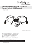
There are three types of modules that can be installed in the rear panel of the
Matrix 100: MRAM module, for RGB; Sync module, for Horizontal and/or Vertical
Sync; and Composite Video module for Composite Video or S-Video. Positions,
or "planes" 1, 2, and 3 will accommodate only MRAM modules. Planes 4 and 5
will accommodate either Sync or Composite video modules, but not MRAM. A
Matrix unit cannot have one or two MRAM modules; it must have three (for red,
green and blue) or none. The modules could be 4x4, 8x4 or 8x8.
Use this procedure to install any MRAM, Sync or Composite Video module.
Locate the position on the back panel for the new module. An MRAM can only
be installed in the locations marked Red, Blue or Green. A Sync module, or a
Composite Video module can only be mounted in the positions marked as such.
If there is one sync module, it must be in the fourth position (Plane 4).
Configuration plane 1
plane 2
plane 3
plane 4
RGsB
MRAM
MRAM
MRAM
RGBS
MRAM
MRAM
MRAM
Sync
RGBHV
MRAM
MRAM
MRAM
Sync
RGsBSCv
MRAM
MRAM
MRAM
Sync
1 Cv
(could be here)
2 Cv or 1 YC
C-Video
Audio can be included with any of these combinations.
plane 5
Sync
C-Video
C-Video
C-Video
3
1
2
4
3
Figure 4-17. This illustration shows the modules already installed.
_______ Address switches are set according to the physical location.
Back panel markings, such as "Sync" or "Video" should show what is installed in
the Matrix 100. If an I/O module was added or changed to another type, peel off
the black covering to show the proper module identification.
1. Remove the Matrix top cover (procedure on page 4-2).
Locking
Tabs
Squeeze
2. Locate the gray ribbon cables that connect the Main Controller board to the
existing I/O modules and determine where the new module will be
connected. If cables from adjacent modules are in the way, they may be
unplugged and reconnected later.
3. On the rear panel, remove the round plastic plugs (as many as required) from
the holes where the new module will be installed. (See Figure 4-20.)
Figure 4-18. Squeeze the tabs to release the plug.
4. On the new module, remove the nuts from the BNC connectors.
4-9
Extron • Matrix 100 • User’s Manual
Chapter 4 • Matrix 100 Hardware Installation
_ If installing both a Sync module and
a Composite Video module, the Sync
module must be in Plane 4 and the
Composite Video in Plane 5.
There are physical differences
between these two modules. The
Sync module has components some
places on the insides of the boards,
where the Composite Video module
has none.
Figure 4-19. Module differences
5. Mount the module by inserting the BNC connectors through the holes in the
rear panel and secure it in place with the nuts. (Use 9/16" socket.)
6. Check to be sure the address DIP switches are set for the correct Plane
number. These switches are set at the factory but their settings should be
confirmed.
The address switch settings are shown to the left, with their orientation as seen
from the front of the Matrix 100.
Figure 4-20. DIP Switch operation
7. Carefully support the I/O board while pushing the ribbon cable onto its
connector (Red stripe up). Connect the other end to the Main Controller
board. The connectors on the Main Controller board are the same, therefore
the cables can be arranged for neatness. Note the orientation of the red
stripe (pin 1) is to the right when looking from the front of the Matrix.
8. After rechecking all connections, put the cover on the Matrix 100 and secure it
with the six screws. (See page 4-2.)
The new configuration will also
appear in Request ID information
sent to the Host system via the
RS-232 port .
The picture to the right is for an
MRAM module.
Figure 4-21. DIP Switch
settings for each module
Figure 4-22. MRAM Module
Extron • Matrix 100 • User’s Manual
4-10
Chapter 4 • Matrix 100 Hardware Installation
Installing QS-FPC Software Update
1. If the QS-FPC in mounted on the Matrix 100, see the procedure on page 4-2
to open the cabinet and then continue with step 2.
________ Electro-Static Discharge (ESD) can damage IC chips, even when it is not
enough to be humanly detected (felt, heard or seen). Do NOT touch IC chips
without being electrically grounded. (Read warning on page 4-2.)
2. With the top cover off the Matrix, unplug the cable that connects the Front
Panel to the Main Controller board and put it aside.
3. Remove the four (4) screws that hold the QuickSwitch Front Panel Controller
(QS-FPC) to the Matrix cabinet.
Figure 4-23. Remove the Front Panel to access the Software IC Chip.
4. Place the QS-FPC face down on a clean workspace. If necessary, place it on
a soft pad to prevent damage.
_________ Be sure you are electrically grounded.
Figure 4-24. Use the PLCC Chip Puller to remove the Software IC Chip.
5. Use the PLCC IC puller to remove the old Software chip. Squeeze the tool to
align the hooks with the slots provided in opposite corners of chip socket U8.
Insert the hooks, squeeze gently and pull the IC straight out of the socket.
Set the chip aside.
6. Note the orientation of the angled corner of the new Software chip. Orient this
to match the angled corner of the socket and carefully press it in place.
PLCC Chip Puller
4-11
7. Reinstall the cover on the back of the QS-FPC, and reverse the above
procedure to put the Matrix back in place.
Extron • Matrix 100 • User’s Manual
Matrix 100 Switcher
User’s Manual
5
Chapter Five
Windows® Control Software
Installing the Software
Operating Examples
Using Help
Chapter 5 • Windows® Control Software
Extron Matrix Control Software
Extron supplies controller software that runs in the Windows® operating system,
version 3.1 or later. Install the software from the 3.5” floppy disk, just like any
other Windows application. (Run Setup.exe from the floppy disk.) This software,
called “Matrix 100/200 Control Program”, works with both the Matrix 100 and
Matrix 200 switchers. Its operation will be restricted to the features and
configuration of your Matrix.
Communication between the computer software and the Matrix is done
after connecting the computer to the RS-232/RS-422 Port on the rear
panel of the Matrix 100. See Page A-1 for more information on this
port.
Installation of the software creates a Program Group (Windows 3.1) or a Folder
(if Windows 95®) called “Extron Electronics”. Icons for the Control Program and
the Help Program are installed in that group, or folder. Examples follow.
The Window below shows an Extron Program Group. This example is from
Windows 3.1, and it includes Extron’s VTG 200 Control Program installed; you
may not have the VTG 200 Software. (VTG = Video Test Generator)
Figure 5-1. Extron Windows Group Example
Windows Example
With the Matrix 100/200 Control software installed, double-click on the icon. You
will be asked to select the PC’s Comm Port. When communications has been
established, the Matrix Control Software will “read” your matrix.
_______ Although detailed Help is provided in the software, this section of the manual is
to inform the user as to what is available. Remember that this software is for
more than one Matrix. Your version may not look exactly like these examples.
This will open a Control Program Window. (The following example is blank.)
5-1
Extron • Matrix 100 • User’s Manual
Chapter 5• Windows® Control Software
Figure 5-2. Control Program Example
Drag an Input box to an Output box to make a “Tie” or connection.
Clicking on an Input or an Output box will open an appropriate dialog box with a
choice of icons for either Input Devices or Output Devices. Click on the desired
icon to assign it to the selected Input or Output. A Text Box at the bottom,
marked “Caption”, allows the user to type in a name for that device. Click “Ok”
to close the dialog box.
Below is an example of a Matrix Control Program Window complete with
assigned Icons, Captions and Ties, or connections.
Figure 5-3. Configured Matrix Example
Extron • Matrix 100 • User’s Manual
5-2
Chapter 5 • Windows® Control Software
Matrix 100/200 Help
Double-click on the Help Icon (or press F1 at any time) to open the Help
Window. Below is an example of how this might look like.
As with all Windows® Help files, clicking on the underlined words will give more
detailed help.
Extron’s Matrix 100/200 Help Contents
To learn how to use Help, press F1 or choose Using Help from the Help menu
The Matrix Control program communicates with the Extron Matrix 100 and 200 Switchers
through the unit’s RS-232/422 port (defaults to 9600 baud, 8 bit, 1 stop, no parity). It
presents the same functions found on the Front-Panel controller, but in an interactive
graphical interface. Because settings to the Matrix (Ties, Presets, Sequences, Audio
config) are stored in the unit’s memory, several modes of ‘programming’ are possible. It
provides 4 major methods:
■ Remote control and programming of the unit in real time through the RS-232 port.
■ Saving unit’s settings for later restoration to the same unit (backup) or copying to
(programming) another unit. Multiple configurations (programs) can be saved to disk
and any one quickly reloaded later, providing an unlimited number of possible setups.
■ Creating Program byte-strings for application to the Matrix through a third-party control
system.
■ Emulation (off-line) programming of the unit’s settings for copying to the unit at a later
time or another place. Emulation mode also allows creation of programs for any
possible Matrix hardware configuration without being connected to such a unit.
To load a demonstration set of Ties, Presets and Sequences to your Matrix (or Emulate
one) Restore from the DEMO.MTX file which was installed with the Control Program. Use
NEW.INI to clear all settings in a unit.
For Help on specific screens and buttons, click the appropriate item below:
Buttons & Controls of the Matrix Main Screen (graphically)
Buttons & Controls of the All other Screens
Note that pressing F1 from within the program will provide context-sensitive Help.
Figure 5-4. Example of the Help Menu
5-3
Extron • Matrix 100 • User’s Manual
Chapter 5• Windows® Control Software
Matrix 100 Switcher
User’s Manual
A
Appendix A
RS-232 Programmer’s Guide
Control Ports
Host/Matrix Data Format
Command Structure
Communications Protocol
Using Commands
Extron • Matrix 100 • User’s Manual
Appendix A • RS-232 Matrix Programmer’s Guide
Control Ports
The picture below shows the connectors for two Control Ports.
Figure A-1. Matrix 100 Port Locations on the Rear Panel
QS-FPC Control Ports
The Front Panel Controller (QS-FPC) can be used two ways: It can be mounted
directly to the Matrix 100, in which case it is connected to an RJ45, 8-pin
connector on the Main Controller board. The QS-FPC can also be dismounted
from the front of the unit and used remotely at a distance of up to 100 feet. For
remote operation, the QS-FPC is connected to the "Remote FPC" port, located
on the rear panel. (See figure.) The pin configuration for the Remote QS-FPC
port is shown below.
RJ45 8-pin Connections (Remote QS-FPC)
Pin Signal Pin
Signal
1
Gnd
5
n/c
2
Gnd
6
Tx
3
Rec
7
+5
4
n/c
8
+5
9-Pin Communication Connector
The RS-232/422 connector is a 9-pin D female with the following pin
designations:
Pin
1
2
3
4
5
6
7
8
9
RS-232
n/c
Tx
Rx
n/c
Gnd
n/c
n/c
n/c
n/c
Description
No Connection
Transmit Data
Receive Data
No Connection
Signal Ground
No Connection
No Connection
No Connection
No Connection
RS-422
TxD(-)
TxD(+)
Rx(+)
Rx(-)
Gnd
n/c
n/c
n/c
n/c
Description
Transmit Data (-)
Transmit Data (+)
Receive Data (+)
Receive Data (-)
Ground
No Connection
No Connection
No Connection
No Connection
The remaining sections of this appendix cover the details of programming the
Matrix 100, from a Host system, connected to the RS-232 port. Before getting
into the commands, the next few pages provide some preliminary information.
Host/Matrix Data Format
Data exchange between the Matrix 100 RS-232 Controller and external control
host is based on a proprietary format and protocol. The communications is byteoriented. Any bytes fall into one of three categories:
Communication control
Matrix 100 command codes
Specific data
00 thru 1F hex
20 thru 7F hex
80 thru FF hex
Bits 0 thru 6 may be binary encoded, or they may represent numbers 00 thru 7F
hex (decimal 0 thru 127).
A-1
Extron • Matrix 100 • User’s Manual
Appendix A • RS-232 Matrix Programmer’s Guide
Binary/hex/decimal Conversion Table
The table below shows how to convert data bytes from one numbering system
to another. In Matrix 100 communications, all data bytes are identified by having
bit 7 = 1, therefore it is not included in the computations.
Bit #s in byte: 7
6
5
4
3
2
Decimal value n/a
64
32
16
8
4
Dec. Hex Add the decimal values above for equivalents.
0
80/00h n/a
0
0
0
0
0
1
81/01h n/a
0
0
0
0
0
2
82/02h n/a
0
0
0
0
0
3
83/03h n/a
0
0
0
0
0
4
84/04h n/a
0
0
0
0
1
5
85/05h n/a
0
0
0
0
1
6
86/06h n/a
0
0
0
0
1
7
87/07h n/a
0
0
0
0
1
8
88/08h n/a
0
0
0
1
0
9
89/09h n/a
0
0
0
1
0
10 8A/0Ah n/a
0
0
0
1
0
11 8B/0Bh n/a
0
0
0
1
0
12 8C/0Ch n/a
0
0
0
1
1
13 8D/0Dh n/a
0
0
0
1
1
14 8E/0Eh n/a
0
0
0
1
1
15 8F/0Fh n/a
0
0
0
1
1
16 90/10h n/a
0
0
1
0
0
etc.
32 A0/20h n/a
0
1
0
0
0
etc.
64 C0/40h n/a
1
0
0
0
0
etc.
99 E3/63h n/a
1
1
0
0
0
100 E4/64h n/a
1
1
0
0
1
etc.
127 FF/7F
n/a
1
1
1
1
1
1
2
0
1
0
0
1
1
0
0
1
1
0
0
1
1
0
0
1
1
0
0
1
0
1
0
1
0
1
0
1
0
1
0
1
0
1
0
0
0
0
0
1
0
1
0
1
1
Command Structure
All commands follow the same pattern:
1. Command Specifier
2. Data (if any)
3. End of Transmission Mark
Command Specifier
The command specifier consists of one byte for short commands or two bytes
for long commands. The first byte is the Command Code (CMD) in the range 20
hex thru 7F hex. The second byte of long commands is called the Subcommand
(SCMD) and is treated as data (ranging from 80 hex to FF hex). A list of
supported commands and detailed explanation are given later in this section.
Data
If present, data quantify the commands. Their format is command-specific. Data
is the useful part of the information exchange - i.e., the reason for sending and
receiving commands. Data is in hexadecimal values, and bit 7 is always a "1",
that is, the data bytes include 80h, plus 7 bits of information.
End of Transmission
This is always (80h 80h 04h).
Extron • Matrix 100 • User’s Manual
A-2
Appendix A • RS-232 Matrix Programmer’s Guide
Host-Initiated Communications Protocol
Most of the information transfer activity is initiated by a Host system, through a
control port. For example, the Host can send Commands to the Matrix to
request data from, or send data to, the Matrix 100. After receiving a command,
the Matrix 100 executes it and sends back a Response to the Host. The
Response includes an error code, together with any requested data.
The Response includes the original Command code. Its format is as follows:
1. Command code – CMD byte (plus SCMD for some commands)
2. Error code
– Erc (see lists)
3. Data (if any) – the number of bytes required for the data
4. 80h, 80h, followed by an “End Of Transmission” mark EOT
Error Codes (Erc)
The error code is usually bit-encoded and follows the data format (bit-7 always
"1", to indicate a data byte). An error code of 80 (hex) indicates "no error." Other
error codes specify the reason for not properly executing a command. The first
error condition encountered will determine the error code. The following list has
Erc codes that could occur in response to any command, and others that are
associated with specific commands. (See command for description.)
Erc -description
Erc - description
Erc - description
80h - no error (normal) 81h - checksum error 82h - illegal command
90h - no I/O boards
91h - system mis-match 92h - security code error
The following error codes are related to specific commands.
Erc - see command
C0 - CMD7
C3 - CMD10
A-3
Erc - see command
C1 - CMD8
D3 - CMD1
Erc - see command
C2 - CMD11
Extron • Matrix 100 • User’s Manual
Appendix A • RS-232 Matrix Programmer’s Guide
Matrix-Initiated Communications Protocol
Sometimes, under abnormal conditions, the Matrix 100 may detect a situation
that must be reported to the Host. For example: Auxiliary power supply has
been activated, memory error, backup battery must be replaced etc. These
Matrix Reports are listed and explained later. They have the same general
command format as the Host-initiated commands, but no response is expected
from the host.
Timing
When Commands are sent to the Matrix 100 switcher, the response is delayed
due to normal processing time. The response time has two components: RS232 or RS-422 bus delay and Matrix 100 processing time. Matrix 100 processing
time is variable, depending on the length of the command and the matrix size.
Response time is usually less than 100 msec.
Command List (Host-to-Matrix)
Command
CMD0
CMD1
CMD2
CMD3
CMD4
CMD5
CMD7
CMD8
CMD9
CMD10
CMD11
CMD12
CMD13
CMD25
CMD26
Hex
30
31
32
33
34
35
37
38
39
3A
3B
3C
3D
49
4A
Page
A-5
A-6
A-7
A-7
A-7
A-9
A-9
A-10
A-10
A-10
A-10
A-11
A-11
A-12
A-12
Description
request status (requires SCMD)
request System ID information (requires SCMD)
turn power ON
turn power OFF
request software version
set (tie) single connection
set (tie) all connections
request status and presets
mute all planes
save current as preset #
load preset #
mute selected outputs
request Mute map
set RGB delay (after sync, for clean switching)
request RGB delay setting
SCMD = Subcommand, a second byte that further defines the Command.
Reports (Matrix-to-Host)
Command
RPRT0
RPRT1
Hex
70
71
Command
CR
EOT
STX
ETX
X-On
X-Off
Hex
0D
04
02
03
11
13
Page Description
A-13 report status to host
A-13 report controlling port
Communication Control
Extron • Matrix 100 • User’s Manual
Description
carriage return
end of transmission
start of text
end of text
resume transmission
interrupt transmission
A-4
Appendix A • RS-232 Matrix Programmer’s Guide
Using Commands
The remainder of this appendix explains the operation of each command,
including data byte breakdown, responses and possible error codes.
CMD0 (30h) - Send Status
The Host asks the Matrix for its status settings.
Format:CMD0, SCMD, 80h, 80h, 04h
Where: SCMD = 080h = send status bytes
81h-8Fh = reserved
Response: CMDØ, SCMD, Erc, Status1, Status2, Status3, 80h, 80h, 04h
Format:30h, 80h, Erc, StsB1, StsB2, StsB3, 80h, 80h, 04h
Status Bytes (StsB1-3) are described below.
Status Byte 1:
7
6
5
4
3
2
1
0
Bit usage:
1
Prg
Seq
Slv
Ver
Gnlk
Batt
Pwr
Where: StsB1, Bit-0 – Power On/Off status - 0 = powered on; 1 = powered off
StsB1, Bit-1 – Backup battery status - 0 = battery okay; 1 = battery low
StsB1, Bit-2 – Genlock Signal - 0 = detected; 1 = not detected
StsB1, Bit-3 – Vertical interval switching - 0 = disabled; 1 = enabled
StsB1, Bit-4 – Slave status - 0 = stand alone unit or master controller
1 = slave in a compound matrix
StsB1, Bit-5 – Sequence running - 0 = not running; 1 = running
StsB1, Bit-6 – Program status - 0 = no program event pending;
1 = program event pending (timer is set)
Status Byte 2:
7
6
5
4
3
2
1
0
Bit usage:
1
0
0
0
0
H-Sec
0
Ps
Where: StsB2, Bit 0 – Power Supply in use - 0 = Backup Power; 1 = Main
Power
StsB2, Bit 2 – Hardware Security status - 0 = locked; 1 = unlocked
(available to user, when unlocked)
StsB2, Bits 1 and 3-6 are reserved (should be zero)
Status Byte 3:
7
6
5
4
3
2
1
0
Bit usage:
1
0
0
0
0
0
0
S-Sec
Where: StsB3, Bit 0 – Software Security status - 0 = locked; 1 = unlocked
(available to user, when unlocked)
StsB3 Bit-1 thru 6 are reserved (should be zero)
A-5
Extron • Matrix 100 • User’s Manual
Appendix A • RS-232 Matrix Programmer’s Guide
CMD1 (31h) - Report ID
The Host asks for the configuration of the Matrix. This includes such information
as, what type of switching modules are installed in which planes, etc.
Format:CMD1, SCMD, 80h, 80h, 04h
SCMD 80h
81h
82h
83h
Reserved
Reserved
Report technology (See example)
Reserved
Example:
SCMD = 82hReport Technology (See example at bottom of page.)
Response:
CMD1, 82h, Erc, *{(BdAd, #Inp, #Out, Tech, CR), ...} 80h, 80h, 04h
Possible Ercs:
D3 - No I/O boards detected.
_______ The string of data bytes in parentheses is shown for one switcher, or plane;
there will be an additional string for each additional plane in the Matrix 100.
They will be transmitted in the ascending order of their board addresses (plane
#1 first).
Where: BdAd = board (or plane) address (plane #1 = 80h, plane #2 = 81h, etc.)
#Inp = number of inputs on this plane
#Out = number of outputs on this plane
Tech = See table.
The Tech byte encodes the basic design characteristics for which the board in
that position was designed.
Tech
80h
81h
82h
83h
84h
FFh
Designed For
Hi-Resolution RGB (HRAM)
Sync
Low Resolution Video
Medium-Res RGB (MRAM)
Audio
Error
Features
250 MHz DC-coupled, no clamping
TTL level
30 MHz (Composite video or S-Video)
175 MHz
Balanced
Mixed technologies (as in composed
matrices)
An example response to a Report Technology command for a Matrix with 8x8
RGBS, 4x4 Composite Video and 8x8 Audio could be:
31, 82, 80, (CMD1, SCMD, Erc)
80, 88, 88, 80, 0D, 81, 88, 88, 80, 0D, 82, 88, 88, 80, 0D, (Red, Green, Blue)
83, 88, 88, 81, 0D, 84, 84, 84, 82, 0D, 85, 88, 88, 84, 0D, (Sync, C-video,
Audio)
80, 80, 04 (Checksum and End of Transmission)
Extron • Matrix 100 • User’s Manual
A-6
Appendix A • RS-232 Matrix Programmer’s Guide
CMD2 (32h) - Turn Power On
The Host tells the Matrix to turn power on.
Format: CMD2, 80h, 80h, 04h
Example: 32h, 80h, 80h, 04h
Response: CMD2, Erc, 80h, 80h, 04h
CMD3 (33h) - Turn Power Off
The Host tells the Matrix to turn power off. The action is independent of other
active control ports, e.g., Front Panel Controller.
Format: CMD3, 80h, 80h, 04h
Example: 33h, 80h, 80h, 04h
Response: CMD3, Erc, 80h, 80h, 04h
CMD4 (34h) - Send Software Version
The Host asks the Matrix to send the current software version.
The format is "x.y".
Format:CMD4, 80h, 80h, 04h
Example: 34h, 80h, 80h, 04h
Response: CMD4, Erc, SfVer, 80h, 80h, 04h
Example: Assuming software version is 1.3 (x=1, y=3)
To determine the SfVer from x.y:
1. Calculate 10x + y (decimal) (10x1 + 3 = 13d)
2. Convert to hex (13d = Dh)
3. Force bit 7 to become 8Dh
The response is 34h, 80h, 8Dh, 80h, 80h, 04h
A-7
Extron • Matrix 100 • User’s Manual
Appendix A • RS-232 Matrix Programmer’s Guide
Set (Tie) Connection Commands
The Set Connection Commands that follow are the programming equivalent of
the Tie Menus used from the QS-FPC.
3
1
2
4
3
Planes and Plane Maps
When looking at the rear panel of the Matrix 100, the planes are counted from
left-to-right, top-to-bottom. Presently, six planes (switching modules) are
supported with hardware. Planes 1, 2, and 3 are reserved for Red, Green, and
Blue modules. Planes 4 and 5 can have either sync or video switching modules,
depending on how the Matrix 100 was configured at the factory. A Matrix, built
with both a sync and composite video switcher, will have the sync module in
plane 4 and the composite video module in plane 5. Plane 6 is reserved for
stereo audio.
The Matrix 100 can access the planes independently, or in combinations, or
groups. Commands can access the planes, by using Plane Map bytes, called
PlnMap0 and PlnMap1. (PlnMap1 is not used at this time.)
Examples below show the correlation between the planes and the bit numbers.
PlnMap0 to access the RGBS Switcher (planes 1, 2, 3 & 4)
Plane #
n/a
7
6
5
4
3
2
1
Plane Use
n/a
Audio Audio Sync/ Sync/ Blue Green Red
#2
#1
Video Video MRAM MRAM MRAM
PlnMap Bit #
7
6
5
4
3
2
1
0
8F hex
1
0
0
0
1
1
1
1
PlnMap0 to access the Composite Video Switcher (plane 5)
Plane #
n/a
7
6
5
4
3
2
1
Plane Use
n/a
Audio Audio Sync/ Sync/ Blue Green Red
#2
#1
Video Video MRAM MRAM MRAM
PlnMap Bit #
7
6
5
4
3
2
1
0
90 hex
1
0
0
1
0
0
0
0
PlnMap0 to access the Audio Switcher (plane 6)
Plane #
n/a
7
6
5
4
3
2
1
Plane Use
n/a
Audio Audio Sync/ Sync/ Blue Green Red
#2
#1
Video Video MRAM MRAM MRAM
PlnMap Bit #
7
6
5
4
3
2
1
0
A0 hex
1
0
1
0
0
0
0
0
______ The plane number refers to the physical address of the I/O module.
Extron • Matrix 100 • User’s Manual
A-8
Appendix A • RS-232 Matrix Programmer’s Guide
CMD5 (35h) - Set (Tie) Connection
The Host tells the Matrix to connect the specified output (Out#) to the specified
input (Inp#) in those planes specified by PlnMap0. (Plane maps are explained
earlier in this section.)
Format: CMD5, PlnMap1, PlnMap0, Out#, Inp#, 80h, 80h, 04h
Example: 35h, 80h, 87h, 83h 85h, 80h, 80h, 04h
This example will connect output #3 to input #5 in RGB planes.
PlnMap1 is not used at this time, therefore it will be 80h.
PlnMap0 = 87h (bits 0, 1, 2 = 1, 1, 1 for the Red, Green and Blue planes)
See Plane Map on previous page.
Out# = 83h = Output #3
Inp# = 85h = Input #5
Response: CMD5, Erc, 80h, 80h, 04h
CMD7 (37h) - Set (Tie) All Connections
The Host tells the Matrix to set connections for any (or all) planes in Matrix. The
planes must be specified by board address (BdAd), in sequential order. A preset
number is assigned for saving this configuration. The configuration may be
loaded later by selecting the preset number.
Format:CMD7, Preset, {(BdAd, Inp1, Inp2, .. Inpn, CR), ..}, 80h, 80h, 04h
Example: 37h, 82h, 80h, 83h, 83h, 85h, 80h, 80h, 80h, 81h, 81h, 0Dh, 81h...
80h, 80h, 04h
Where:
A) Preset is the number assigned to this configuration (example is preset
#2).
Preset numbers can be 1 - 8 (81h - 94h). If the information is to be used as
the current Matrix configuration, without saving it as a preset, the number
for this will be zero (80h).
B) (BdAd, Inp1, Inp2, .... Inpn, CR) is a string of bytes for each plane record,
with the following components:
a. BdAd is the board address for the plane (example is 80h = red
plane).
b. Inp1 is the input # to connect to output #1. (example ties input #3)
Inp2 is the input # to connect to output #2. (example ties input #3)
c. Inpn is the input# to connect to the last output. (example ties input
#1)
d. CR - carriage return (0Dh) terminates the data string for this plane.
C) Another plane record (data string) will follow for the next plane to be
configured - and another, etc. for each plane to be configured.
_______ 1. The plane record has a length determined by the number of outputs (n).
2. Only existing planes are valid.
3. Any, or all, valid planes may be specified in the same command.
4. Planes must be specified in ascending BdAd address order.
(Plane 1 first; plane n last.)
Response: CMD7, Erc, 80h, 80h, 04h
Possible Ercs: C0 = Out of memory space
A-9
Extron • Matrix 100 • User’s Manual
Appendix A • RS-232 Matrix Programmer’s Guide
CMD8 (38h) - Download Status and Presets
The Host asks the Matrix 100 to send the contents of the specified preset.
Same variables are used as in CMD7. Stored presets are numbered 1 thru 8.
_______ The current Matrix setup can be accessed as preset # 0.
Format: CMD8, Preset, 80h, 80h, EOT
Response: CMD8, Erc, {(BdAd, Inp1, Inp2, ...Inpn, CR), ...}, 80h,
80h, 04h
Possible Ercs: C1 = Preset file not found
Where: Preset can be 80h (current configuration) or 81h (1) thru 88h (8).
As described in CMD7, there is a data string for each plane, starting with its
board address (BdAd) and ending with 0Dh (carriage return).
CMD9 (39h) - Mute All Planes
The Host instructs the Matrix to mute (deactivate) all outputs in specified
planes.
Format: CMD9, PlnMap1, PlnMap0, 80h, 80h, 04h
Where: PlnMap1 and PlnMap0 follow the format described for CMD1.
Bits are "0" for normal operation and "1" to mute the plane.
Example: If PlnMap1, PlnMap0 = 080h, 083h. Red and Green channels are
muted. All RGB displays connected to Matrix 100 outputs will show only the
blue component of the signal.
_______ At this time, only PlnMap0 is supported by hardware. PlnMap1 = 80h.
Bits for nonexisting planes are forced to 0.
CMD10 (3Ah) - Save Current as Preset #
The Host tells the unit to save its current connections as a preset.
(The preset can be called later using CMD11.)
Format: CMD10, Preset, 80h, 80h, 04h
Where: Preset can be 81h (1) thru 88h (8).
Response: CMD10, Erc, 80h, 80h, 04h
Possible Ercs: C3 = Out of memory space
CMD11 (3Bh) - Load Preset #
The Host tells the Matrix to load (activate) a stored preset configuration. The
connections previously stored under the specified preset number become
active. The current connections are lost, unless they have also been saved as a
preset.
Format:CMD11, Preset, 80h, 80h, 04h
Response: CMD11, Erc, 80h, 80h, 04h
Possible Ercs: C2 = Preset file not found
Extron • Matrix 100 • User’s Manual
A-10
Appendix A • RS-232 Matrix Programmer’s Guide
CMD12 (3Ch) - Mute Selected Outputs
The Host tells the Matrix to mute specific planes, within selected outputs.
Format:CMD12, Mute1, Mute2, ... MuteN, 80h, 80h, 04h
Where: MuteN specifies planes to be muted for the output corresponding to the
mute byte number. This uses the same format as PlnMap shown below.
MRAM = Medium Resolution
Analog Module.
PlnMap0 to access the RGBS Switcher (planes 1, 2, 3 & 4)
Plane #
n/a
7
6
5
4
3
2
1
Plane Use
n/a
Audio Audio Sync/ Sync/ Blue Green Red
#2
#1
Video Video MRAM MRAM MRAM
PlnMap Bit #
7
6
5
4
3
2
1
0
MuteN
1
x
x
x
x
x
x
x
Example: Assume an 8 x 8 switch, with RGBS, Composite video and Audio.
3Ch, 87h, A0h, 90h, 97h, 80h, 80h, 80h, 80h, 80h, 80h, 04h
The following outputs are muted:
87h
Output 1:
R, G, B (leave sync on)
A0h
Output 2:
Audio Stereo (Left + Right)
90h
Output 3:
Composite video
97h
Output 4:
R, G, B and Composite video
80h
outputs 5 - 8
Outputs not muted
Response: CMD12, Erc, 80h, 80h, 04h
CMD13 (3Dh) - Request Mute Map
The Host asks the Matrix to send which outputs are muted. The response sends
back the same data, in the same format as CMD12.
Format:CMD13, 80h, 80h, 04h
Example: 3Dh, 80h, 80h, 04h
Response: CMD13, Erc, Mute1, Mute2, ... MuteN, 80h, 80h, 04h
Where: MuteX specifies planes to be muted for the output corresponding to the
mute byte number. This uses the same format as PlnMap shown above.
A-11
Extron • Matrix 100 • User’s Manual
Appendix A • RS-232 Matrix Programmer’s Guide
CMD25 (49h) - Set RGB Delay
The Matrix is instructed to set values for RGB delay. When switching occurs,
the R, G and B switching will take place after the specified time delay. The sync
switching takes place immediately, but the RGB outputs are muted during this
delay period. This allows the projector to get in sync before the picture arrives,
providing seamless switching.
Format:CMD25, Dly1, Dly2, .... DlyN, 80h, 80h, 04h
Where: Bits 0-6 of each “Dly” byte represent the RGB-to-sync delay for that
output (expressed in increments of 0.1 sec). "N" represents the number of last
available output, as determined by command CMD1. (Dly1 = output #1; Dly2 =
output #2, etc.)
Delays must be specified for each output. For zero time delay, DLY = 80h. The
time delay depends on the requirements of the output device (projector, etc.).
Example: 49h, 84h, 90h, etc. says the RGB for output #1 (84h) will be delayed
by 0.4 seconds, and output #2 (90h) will be delayed by 1.6 seconds, etc.
Response: CMD25, Erc, 80h, 80h, 04h
CMD26 (4Ah) - Request RGB Delay Information
The Host asks the Matrix to send delay switching information for each of the
RGB planes.
Format:CMD26, 80h, 80h, 04h
Example: 4Ah, 80h, 80h, 04h
Response: CMD26, Erc, Dly1, Dly2, .... DlyN, 80h, 80h, 04h
Where: The “Dly” characters have the same significance as in previous
command (CMD25). "N" represents the number of last available output, as
determined by command CMD1. (Dly1 = output #1; Dly2 = output #2, etc.)
Extron • Matrix 100 • User’s Manual
A-12
Appendix A • RS-232 Matrix Programmer’s Guide
Reports (Matrix-to-Host)
Report0 (70h) - Status
This report is broadcast when a change in internal status is detected.
Format:RPRT0, StsB1, StsB2, StsB3, 80h, 80h, 04h
Status Byte 1:
Bit usage:
Where: StsB1,
StsB1,
low
StsB1,
StsB1,
StsB1,
7
1
5
Seq
4
Slv
3
Ver
2
Gnlk
1
Batt
0
Pwr
Bit-0
Bit-1
Power On/Off status - 0 = powered on; 1 = powered off
Backup battery status - 0 = battery okay; 1 = battery
Bit-2
Bit-3
Bit-4
Genlock Signal - 0 = detected; 1 = not detected
Vertical interval switching - 0 = disabled; 1 = enabled
Slave status - 0 = stand alone unit or master controller
1 = slave in a compound matrix
Sequence running - 0 = not running; 1 = running
Program status - 0 = no program event pending;
1 = program event pending (timer is set)
StsB1, Bit-5
StsB1, Bit-6
Status Byte 2:
Bit usage:
6
Prg
7
1
6
0
5
0
4
0
3
0
2
H-Sec
1
0
0
Ps
Where: StsB2, Bit 0 - Power Supply in use - 0 = Backup Power; 1 = Main Power
StsB2, Bit 2 - Hardware Security status - 0 = locked; 1 = unlocked
(available to user, when unlocked)
StsB2, Bits 1 and 3 thru Bit 6 are reserved (should be zero)
Status Byte 3:
Bit usage:
7
1
6
0
5
0
4
0
3
0
2
0
1
0
0
S-Sec
Where: StsB3 Bit 0 - Software Security status - 0 = locked; 1 = unlocked
(available to user, when unlocked)
StsB3 Bit-1 thru 6 are reserved (should be zero)
Report1 (71h) - New Controlling Port
This report is broadcast when a change in the connections (current or presets)
or the operating mode is requested (and implemented) by a new port.
Commands CMD5, 7, 9, 11, 12, and 25 will cause this report to be sent.
Format:RPT1,
Where: Port#
80h
81h
82h
83h
A-13
Port#, 80h, 80h, 04h
as follows ...
host controller (RS-232/RS-422)
n/a
standard front panel controller port
secondary front panel controller port
Extron • Matrix 100 • User’s Manual
Appendix A • RS-232 Matrix Programmer’s Guide
Matrix 100 Switcher
User’s Manual
B
Appendix B
Part Numbers & Reference
Related Part Numbers
Switcher Module Part Numbers
BNC Cables
Matrix 100 Numbering System
Limited Warranty
Extron • Matrix 100 • User’s Manual
Appendix B • Part Numbers and Reference
Related Part Numbers
Extron Part
Part #
Blank Front Panel
60-147-01
Front Panel Controller (QS-FPC)
60-188-01
Audio Connectors (Phoenix)
10-163-01
SVHS-to-BNC Adapter
26-353-01
GLI 250
60-123-01
- (Ground Loop Isolator, 250 MHz RGBHV)
PA 250
60-124-01
- (Peaking Amplifier, 200 MHz RGBS)
Matrix 100 User's Manual
68-199-01 - (this manual)
SC 110 Sync Combiner (115v)
60-153-01 (230v = 60-153-02
SC 210 Sync Processor (115v)
60-154-01 (230v = 60-154-02)
Option Kit Part Numbers
Kits can be ordered from Extron for adding modules to an existing Matrix 100.
The following list gives part numbers for available kits.
Matrix 100 Option Kit
Redundant Power Supply
8 x 8 Stereo Audio Module
4 x 4 MRAM (for RGB)
8 x 4 MRAM (for RGB)
8 x 8 MRAM (for RGB)
4 x 4 Sync Module
8 x 4 Sync Module
8 x 8 Sync Module
4 x 4 Composite Video
8 x 4 Composite Video
8 x 8 Composite Video
Part #
70-020-01
70-039-01
70-041-01
70-041-02
70-041-03
70-024-01
70-024-02
70-024-03
70-025-01
70-025-02
70-025-03
These kits include all the necessary parts, as well as instructions for a qualified
person to add options to a Matrix 100. Chapter 2 of this manual also has some
procedures for adding options.
B-1
Extron • Matrix 100 • User’s Manual
Appendix B • Part Numbers and Reference
BNC-4 Cables (High Resolution BNC Cables)
Extron BNC-4 cables are high resolution (HR) BNC cables, color coded with
solid colors and wrapped in a single jacket. The total cable diameter is 0.398".
Extron recommends that when using signals with a scanning frequency of 15125 kHz and running distances of 100 feet or more, high resolution BNC cables
should be used to achieve maximum performance. The following cables are
stock lengths:
Cable -Length
Part #
BNC-4-3' HR ................ 26-210-01
BNC-4-6' HR ................ 26-210-02
BNC-4-12' HR .............. 26-210-03
BNC-4-25' HR .............. 26-210-04
BNC-4-50' HR .............. 26-210-05
BNC-4-75' HR .............. 26-210-06
BNC-4-100' HR ............ 26-210-07
BNC-4-150' HR ............ 26-210-08
BNC-4-200' HR ............ 26-210-09
BNC-4-300' HR ............ 26-210-53
BNC-4-500' HR ............ Bulk Length
BNC-4-1000' HR .......... Bulk Length
_______ Bulk cable in lengths up to 5000' rolls is available with or without connectors.
BNC Cable Specifications
Conductors .................. Silver Plated Alloy
Insulation ..................... Foam Polypropylene
Nominal Outer Dimension
0.398"
DC Resistance ............. 41.5 Ohms/1000 ft.
Impedance ................... 75.5 Ohms, Nominal
Time Delay .................. 1.28 Nanoseconds/ft.
Capacitance ................. 17 pF/ft.
BNC-5 HR Cables
High resolution 5 conductor BNC cables include cables for Red, Green, Blue,
Horizontal and Vertical Sync. These cables are required when using the
Matrix 100 with separate horizontal and vertical sync inputs and outputs. The
specifications are the same for the BNC-5 HR and BNC-4 HR cables.
Extron • Matrix 100 • User’s Manual
B-2
Appendix B • Part Numbers and Reference
Matrix 100 Part Numbering System
The Matrix 100 can be factory-configured with many combinations of switcher
modules. The diagram below illustrates how the part numbers are derived.
All Matrix 100 part numbers begin with 60-182, the remaining digits are
determined by other options. Use this diagram when ordering a new Matrix 100.
_______ 1. S-Video uses two
Composite Video modules.
The hardware is the same,
the difference is how they
are used.
2. If a Matrix has S-Video, it
cannot have a sync module.
Example 1:
A Matrix 100 with
8x8 RGB,
8x8 Hor. & Vert. sync,
Stereo Audio,
QS-FPC and a
Redundant Power Supply
will have the part number:
60-182DXAZB
Example 2:
A Matrix 100 with
8x4 RGsB,
8x4 S-Video,
Stereo Audio,
and a QS-FPC
will have the part number:
60-182CVAZH
Example 3:
A Matrix 100 with
4x4 RGBS,
8x4 Composite Video,
and a Blank Front Panel
will have the part number:
60-182BKBYA
This number will be on a
label on the shipping box.
B-3
Extron • Matrix 100 • User’s Manual