1
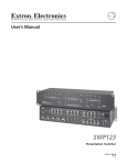
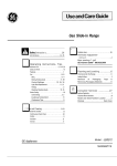
MSX1616 / MSX1616HR MATRIX SWITCHER 16–INPUT, 16–OUTPUT MSX1616/MSX1616HR OPERATION MANUAL High Resolution Video Products • A/V System Integration Tools • Interactive Training Systems Installation and Safety Instructions For Models without a Power Switch: The socket outlet shall be installed near the equipment and shall be accessible. For all Models: No serviceable parts inside the unit. Refer service to a qualified technician. For Models with Internal or External Fuses: For continued protection against fire hazard, replace only with same type and rating of fuse. Instructions d’installation et de sécurité Pour les modèles sans interrupteur de courant: La prise de courant d’alimentation sera installé près de l’équipement et sera accessible. Pour tout les modèles: Pas de composants à entretenir à l’intérieur. Confiez toute réparation à un technicien qualifié. Pour les modèles équipés de fusibles internes ou externes: Afin d’éviter tout danger d’incendie, ne remplacer qu’avec le même type et la même valeur de fusible. Installations- und Sicherheitshinweise Für Geräte ohne Netzschalter: Die Netzsteckdose soll in der Nähe des Gerätes installiert und frei zugänglich sein. Für alle Geräte: Keine Wartung innerhalb des Gerätes notwendig. Reparaturen nur durch einen Fachmann! Für Geräte mit interner oder externer Sicherung: Für dauernden Schutz gegen Feuergefahr darf die Sicherung nur gegen eine andere gleichen Typs und gleicher Nennleistung ausgewechselt werden. Instalacion E Instrucciones de Seguridad Modelos Sin Interruptor: La conexión debe ser instalada cerca del equipo y debe ser accesible. Para Todos Los Modelos: Dentro de la unidad , no hay partes para reparar. Llame un tecnico calificado. Modelos con Fusibles Internos o Externos: Para prevenir un incendio, reemplace solo con el mismo tipo de fusible. CE COMPLIANCE All products exported to Europe by Inline, Inc. after January 1, 1997 have been tested and found to comply with EU Council Directive 89/336/EEC. These devices conform to the following standards: EN50081-1 (1991), EN55022 (1987) EN50082-1 (1992 and 1994), EN60950-92 Shielded interconnect cables must be employed with this equipment to ensure compliance with the pertinent Electromagnetic Interference (EMI) and Electromagnetic Compatibility (EMC) standards governing this device. FCC COMPLIANCE This device has been tested and found to comply with the limits for a Class A digital device, pursuant to Part 15 of the FCC rules. These limits are designed to provide against harmful interference when equipment is operated in a commercial environment. This equipment generates, uses and can radiate radio frequency energy and, if not installed and used in accordance with the instruction manual, may cause harmful interference to radio communications. Operation of equipment in a residential area is likely to cause harmful interference, in which case the user will be required to correct the interference at their own expense. Table of Contents MSX1616 Matrix Switcher - Quick Start..................................................................................... 3 Installation ..........................................................................................................................3 Front Panel Controls ...........................................................................................................4 Functionality .......................................................................................................................4 Creating new patches............................................................................................4 Adjusting audio levels ..........................................................................................4 Creating a preset ...................................................................................................4 Viewing switches..................................................................................................4 Product Overview........................................................................................................................... 5 Description..........................................................................................................................5 Product Features .................................................................................................................5 MSX1616 model Numbers .................................................................................................6 Installation ...................................................................................................................................... 7 Mounting the MSX1616 .....................................................................................................7 Device Connections ............................................................................................................7 Power Connection...............................................................................................................7 Video Input and Output Connections..................................................................................8 Audio Input and Output Connections .................................................................................8 Serial Ports..........................................................................................................................9 RS-232/422/485 Connections .............................................................................................9 DIP Switch Settings: Standard...........................................................................................9 DIP Switch Settings: Termination ...................................................................................10 Compatibility ................................................................................................................................ 12 Input..................................................................................................................................12 Output ...............................................................................................................................12 Operation ...................................................................................................................................... 15 Front Panel Controls .........................................................................................................15 Front Panel Operation .......................................................................................................16 Creating a Patch in Matrix Mode......................................................................................16 Creating Presets in Matrix Mode ......................................................................................16 To recall a saved preset: .....................................................................................17 Previewing Patches in Preview Mode...............................................................................17 Recalling Presets in Express Mode ...................................................................................17 Hierarchy of LCD Screens .......................................................................................................... 18 Menu Programming..................................................................................................................... 19 Level Selection .................................................................................................................19 In or Out............................................................................................................................19 Audio Setup ......................................................................................................................20 Advanced Menu ................................................................................................................21 Setting up Serial Ports ........................................................................................21 Resetting the Switcher ........................................................................................22 Activating RGB Delay........................................................................................22 Remote Operation ........................................................................................................................ 23 Communication Protocol ..................................................................................................23 Control Port 1 .....................................................................................................23 Protocol Structure ...............................................................................................23 Auxiliary Ports 2 and 3 .......................................................................................24 Input and Output Codes ......................................................................................24 Preset Codes .......................................................................................................24 Serial Port Pin-outs ...........................................................................................................25 2002 - INLINE, INC. MSX1616 OPERATION MANUAL - v1.0 5/8/02 2 Serial Commands ......................................................................................................................... 26 Addressing Commands .....................................................................................................26 Set-Up Commands ............................................................................................................27 Level Commands ..............................................................................................................28 Switching Commands .......................................................................................................29 Volume Commands ..........................................................................................................30 Auxiliary Commands ........................................................................................................33 Preset Commands .............................................................................................................35 Preset Label Commands ...................................................................................................36 Warranty....................................................................................................................................... 38 MSX1616 OPERATION MANUAL - v1.0 5/8/02 2002 - INLINE, INC. 3 MSX1616 Matrix Switcher - Quick Start Installation Step 7 Step 1 If you will be controlling the switcher with serial commands, cable the control system or computer serial port to serial port 1 based on the type of connection described below. Install the switcher into a standard 19" equipment rack, or set it on a flat surface. Connect input video sources to the BNC connector inputs. Connect sync inputs to the H/C and V connectors and video inputs to the RGB connectors. Step 3 GND TXTX+ RXRX+ RS-232 Connection Diagram: Step 2 Computer Serial Port (DB-9 Connector) MSV0804 Serial Port 2 RX 3 TX 5 GND GND TXTX+ RXRX+ Full Duplex RS-422/485 Connection Diagram: Connect output devices (monitors, data projectors, etc.) to the BNC outputs. Computer Serial Port (DB-9 Connector) MSV0804 Serial Port Step 4 Connect audio sources to the audio inputs (5-pin captive screw terminals). The wiring diagram below illustrates connections for unbalanced and balanced audio signals. For balanced Stereo Audio Input: RX+ 7 RX- 2 TX+ 6 TX- 5 GND 1 GND Half Duplex RS-485 Connection Diagram: GND TXTX+ RXRX+ For unbalanced Stereo Audio Input: 3 Computer Serial Port (DB-9 Connector) MSV0804 Serial Port 3 RX+ 7 RX- 2 Step 5 TX+ 6 TX- Connect the audio outputs to the audio system’s line level input. 5 GND 1 GND For unbalanced Stereo Audio Output: For balanced Stereo Audio Output: Step 8 Connect power and turn on the switcher, display devices, control, and audio equipment as applicable. Step 6 Select the serial communication protocol format for serial port 1 as required by the control system. Set DIP switches in Switch Bank 1 according to the following chart: Port 1 Serial Format: Switch 1 DIP Switch Settings: RS-232 RS-422/485 Set switches 123 to OFF Set switches 123 to ON 2002 - INLINE, INC. MSX1616 OPERATION MANUAL - v1.0 5/8/02 MSX1616 Matrix Switcher - Quick Start, continued Front Panel Controls Functionality Buttons to the left of the LCD let you navigate through the LCD menu options. Creating new patches Arrowed buttons let you increase or decrease a selection, scroll up or down, move forward and backward, and change inputs and outputs. MENU displays the status menu on the initial press. Subsequent presses display the next menu level up. ENTER saves newly selected menu settings. VOLUME adjusts the volume of the selected audio output or input. MUTE silences the selected audio output. INPUT and OUTPUT buttons configure any number of new patches. TAKE performs the input-to-output switches as configured. PRESET recalls a preset configuration, which includes all input/output patches and volume levels. BLANK acts as an input when creating patches. Use it to blank any or all outputs. CANCEL deletes unsaved configurations. 2002 - INLINE, INC. 1. Press the button of the desired input device. 2. Press the button(s) of the output(s) where you want the input signal sent. 3. Repeat steps 1 and 2 until all connections are defined. 4. Press TAKE to perform the patches. Alternately, use the LCD menu. Adjusting audio levels 1. Use the VOLUME buttons on the front panel to increase or decrease volume level for the currently selected output. 2. Press MUTE to silence the audio output. Creating a preset 1. Set all desired input/output patches, audio levels, and mute states. 2. Press MENU. 3. Select 3UHVHW6WRUH on the LCD. 4. Press any one of the input or output buttons to select a storage location for this preset. Result: The switcher stores the current configuration into memory. Viewing switches 1. On the LCD Menu, select 3UHYLHZ. 2. Select and press an input or output button to see all current switches. Result: The LED indicators above each button glow to indicate all stored patches for those inputs/outputs. MSX1616 OPERATION MANUAL - v1.0 5/8/02 5 Product Overview Description The MSX1616 matrix switcher routes audio and video signals from multiple sources to multiple monitors, screens, and speakers without requiring cable changes. Model Description MSX1616 MSX1616HR MSX3216 MSX3216HR 16 x 16 Matrix for RGBHV & Stereo Audio – 160 MHz 16 x 16 Matrix for RGBHV & Stereo Audio – 475 MHz 32 x 16 Matrix for RGBHV & Stereo Audio – 150 MHz 32 x 16 Matrix for RGBHV & Stereo Audio – 450 MHz Product Features • 475 MHz 16 x 16 HR video bandwidth • 450 MHz 32 x 16 HR video bandwidth • Three RS-232/RS-422/RS-485 Serial Control ports enable third-party control systems to control the switcher using RS-232, RS-422, or RS-485 serial commands. Offers fast communication speed, individual unit addresses, and command buffering. • New Serial Control Protocol for programming serial commands. • Ergonomic Front Panel Design features large rubber buttons with ample room for labels. • Master Volume Control and Mute for each output. • Audio Gain Trim Level Storage is available for each input. • Integrated Labeling System provides attachment posts to hold optional nameplates to engrave or label inputs, outputs, and presets. • Large LCD Status Screen displays system menu and settings • Two Auxiliary Serial Control Ports store and transmit serial commands to control projectors of other serial-controlled equipment. • Genlock Input and Output - Vertical Interval Switching for glitch-free transitions when used with synchronous video sources 2002 - INLINE, INC. MSX1616 OPERATION MANUAL - v1.0 5/8/02 6 • Dual Switching Modes o Matrix mode – Lets you configure new or change existing input-output patches with the press of one button. o Express mode – Lets you recall previously stored input/output patches. • RGB Delay mode for enhanced switching translations. • 256 Configuration Memories let you to store and recall input/output configurations, audio levels, and auxiliary serial commands. • Blank Front Panel Versions are available at a lower cost. MSX1616 model Numbers 16 x 16 Matrix Switcher 160 MHz With Faceplate Without Faceplate RGB/Component Video RGB/Component Video + Balanced Stereo Audio RGBHV RGBHV + Balanced Stereo Audio MSX1616-1 MSX1616-2 MSX1616-3 MSX1616-4 MSX1616-5 MSX1616-6 MSX1616-7 MSX1616-8 16 x 16 Matrix Switcher 475 MHz With Faceplate Without Faceplate RGB/Component Video RGB/Component Video + Balanced Stereo Audio RGBHV RGBHV + Balanced Stereo Audio MSX1616HR-1 MSX1616HR-2 MSX1616HR-3 MSX1616HR-4 MSX1616HR-5 MSX1616HR-6 MSX1616HR-7 MSX1616HR-8 MSX1616 OPERATION MANUAL - v1.0 5/8/02 2002 - INLINE, INC. 7 Installation Mounting the MSX1616 Mount the MSX1616 switcher on a standard 19-inch metal equipment rack. The unit is 6U tall. Allow 1U above and below the switcher for heat dissipation. To rack-mount the switcher: 1. Slide the switcher into the equipment rack. 2. Align the mounting holes of the unit with those of the rack. 3. Fasten the switcher to the rack using the machine screws included with the rack. Device Connections All connections (including switches, serial ports, and power, audio, and video BNC connectors) are on the rear panel of the switcher. Power Connection Attach the power cord to the connector on the rear of the switcher. A standard IEC power cord comes with the unit. Plug it into a 100 – 240 VAC, 50 Hz, or 60 Hz power source. 2002 - INLINE, INC. MSX1616 OPERATION MANUAL - v1.0 5/8/02 8 Video Input and Output Connections Video connections are made with BNC connectors, one for each of five inputs: Red (R), Green (G), Blue (B), Horizontal/Comp Sync (H/C), and Vertical Sync (V). 1. Connect video input devices to the appropriate video input connectors. 2. Connect video output devices to the appropriate video output connectors. The types of video signals the switcher can receive on the RGB input connectors are: • Composite • S- Video • Component • RGB Video The types of signals that the switcher can receive on the H/C and V input connectors are: TTL level sync info Note: Video signals do not pass on sync channels. Audio Input and Output Connections Make audio connections with 5-pin captive screw connectors in a balanced or unbalanced arrangement. Screw connectors come with the MSX1616 switchers. The following diagrams depict proper wiring for balanced and unbalanced inputs and outputs. For Unbalanced Stereo Audio Input: For Balanced Stereo Audio Input: For Unbalanced Stereo Audio Output: For Balanced Stereo Audio Output: Note: Be sure to connect each cable completely. MSX1616 OPERATION MANUAL - v1.0 5/8/02 2002 - INLINE, INC. 9 Serial Ports The switcher features three serial ports that can accommodate RS-232, RS-422, and RS-485 connections. Use serial port 1 to control the switcher using either a PC or a third-party control system. Use serial ports 2 and 3 to control auxiliary devices with serial commands you store into the switcher. RS-232/422/485 Connections RS-232 Connection Diagram: Full Duplex RS-422/485 Connection Diagram: Half Duplex RS-485 Connection Diagram: DIP Switch Settings: Standard DIP switch settings change according to the standard used. Higher standards require a different signal type. DIP switches make subtle adjustments to that signal type. Configure the DIP switch settings according to the following table. Serial port # 1 2 3 RS-232 RS-422/RS-485 SW 1: 123 OFF SW 1: 456 OFF SW 2: 123 OFF SW 1: 123 ON SW 1: 456 ON SW 2: 123 ON The settings of the... First three switches of DIP switch 1 Last three switches of DIP switch 1 First three switches of DIP switch 2 2002 - INLINE, INC. Control serial port #: 1 2 3 MSX1616 OPERATION MANUAL - v1.0 5/8/02 DIP Switch Settings: Termination Switch 1 Position 2 Switch 1 Position 3 Switch 1 Position 4 Switch 1 Position 5 Switch 1 Position 6 Switch 2 Position 1 Switch 2 Position 2 RS232 OFF OFF OFF OFF OFF OFF OFF OFF OFF Do not terminate 422/485 Full duplex termination ON ON ON ON ON ON ON ON ON Terminate if first or last position OFF Do not terminate if center of multi-drop connection OFF Only one termination required at ends OFF Do not terminate if center of multi-drop 485 halfduplex termination Nontermination Function: ON ON ON OFF ON OFF OFF OFF OFF ON ON ON OFF ON OFF OFF OFF OFF ON ON ON OFF ON OFF Switch 2 Technical Position 3 Notes RS232/ Receive Transmit RS232/ Receive Transmit RS232/ Receive Transmit 485 select termination termination 485 select termination termination 485 select termination termination Switch 2/Position 4, Switch 2/Position 5, and Switch 2/Position 6 are reserved for future definition. 2002 - INLINE, INC. PORT 3 Switch 1 Position 1 422/485 Full duplex nontermination 10 PORT 2 MSX1616 OPERATION MANUAL - v1.0 5/8/02 PORT 1 11 MSX1616 DIP switch ON position: MSX3216 DIP switch ON position: 2002 - INLINE, INC. MSX1616 OPERATION MANUAL - v1.0 5/8/02 12 Compatibility Input The MSX1616 16 input connections are terminated with BNC connectors that can accept composite, S-Video component (YUV, YPrPb, YR-Y, B-Y), RGBHV, RGBS, RGsB, or computer pass through singles. You can configure a single input to feed up to 16 different output sources simultaneously, giving you 32 possible input/output configurations. The MSX1616 has analog audio-follow-video and breakaway capability. All analog audio inputs are compatible with balanced and unbalanced line level signals from a computer audio card or any other audio device that delivers a stereo line level signal. Output The MSX1616 can output to 16 separate sources through its BNC connectors. The analog stereo audio output provides a balanced or unbalanced line level signal. This output can drive any line level compatible audio unit or a local device such as powered speakers. MSX1616 OPERATION MANUAL - v1.0 5/8/02 2002 - INLINE, INC. 13 2002 - INLINE, INC. MSX1616 OPERATION MANUAL - v1.0 5/8/02 14 MSX1616 OPERATION MANUAL - v1.0 5/8/02 2002 - INLINE, INC. 15 Operation Front Panel Controls The MSX1616 features the following ergonomic front panel controls. Button Function Soft Keys Menu Navigation Buttons MENU ENTER VOLUME TAKE Navigate through any menu on LCD. Scrolls up and down LCD menu selections and changes inputs/outputs. CANCEL BLANK PRESET INPUT OUTPUT 2002 - INLINE, INC. Displays the previous LCD screen. Saves changes made to existing patches and saves any new settings. Adjusts volume of selected audio output or input. Completes a patch and saves the switch configuration into non-volatile memory. Deletes any unsaved configuration, terminates a patch configuration prior to pressing TAKE, and takes you to the main LCD screen. Turns off (blanks) any output. Recalls an existing preset. Has an LED indicator above it and corresponds to a video input. Has an LED indicator above it and corresponds to an output source on the rear panel. The LED blinks when you create a new patch and glows steady when you press TAKE. MSX1616 OPERATION MANUAL - v1.0 5/8/02 16 Front Panel Operation The MSX1616 series has three operational modes: Matrix, Preview, and Express. • In Matrix mode, you can select an input, assign it to any output or series of outputs, and press TAKE to accept the new switch. Matrix mode allows maximum switching flexibility. • In Preview mode, you can view input/output patches you have created. • In Express mode, you can recall previously saved presets with the press of one button. Non-technical users will find Express mode simple and convenient to use. Creating a Patch in Matrix Mode 1. Press the number of the desired input device. Result: The LED indicator above the button glows. 2. Press the number(s) of the output(s) where you want the input signal sent. Result: The LED indicator blinks. The connection does not yet exist. 3. Press TAKE. Result: The switcher makes the patches, stores the information in memory, and all selected LEDs go out. To confirm the patch: Press the input button again. Result: The LED above each output connected to that input glows. Creating Presets in Matrix Mode Once you create a patch, you can assign the patch a preset number you can recall later without having to reconfigure the patch. 1. Create the desired switch or configuration of input/output connections. 2. Press TAKE. 3. Press MENU until 0DLQ0HQX displays in the LCD. 4. Select 3UHVHW6WRUH on the LCD. Result: 6WRUH3UHVHW displays in the LCD. 5. Press any one of the input or output buttons to pick a storage location for this preset. Result: The switcher accepts the preset and stores it into memory. MSX1616 OPERATION MANUAL - v1.0 5/8/02 2002 - INLINE, INC. 17 To recall a saved preset: 1. To recall a preset, press PRESET. Result: The LEDs above the buttons designating saved presets glow. 2. Select the desired preset by pressing the corresponding button. Note: The MSX1616 includes special labeling strips so you can label what functionality you assigned to which preset. Previewing Patches in Preview Mode Once you create a patch, you can preview it and other existing patches. 1. Press the soft key pointing to 3UHYLHZ. Result: 6HOHFW,1387287387WR9LHZ&XUUHQW&RQQHFWLRQV displays on the LCD. 2. Press any input or output button. Result: The LED above each button corresponding to a patched input/output glows. Press CANCEL to exit Preview mode. If you need to change any patches, exit this feature and follow the Matrix Mode instructions above or press the LCD buttons pointing to ,Q or 2XW. Recalling Presets in Express Mode Express Mode lets you recall presets with the touch of one button. 1. Press PRESET twice in succession. Result: The LCD prompts you to press ENTER to accept or MENU to go back to Matrix Mode. 2. Press ENTER. Result: The LCD indicates that you are in Express Mode. 3. The LED(s) above the buttons corresponding to the first 32 (16 x 16) or 48 (32 x 16) previously saved preset(s) glows. Press one of these buttons to recall the preset associated with it. 4. You will stay in Express mode until you explicitly exit it using a serial command or as explained below. To exit Express mode: Press CANCEL and MENU simultaneously. Result: The LED returns to Matrix Mode and displays the main screen. 2002 - INLINE, INC. MSX1616 OPERATION MANUAL - v1.0 5/8/02 18 Hierarchy of LCD Screens &XUUHQW/HYHO5*%+9$ 3UHYLHZ ,Q 2XW 6HOHFW/HYHO /HYHO5*%+9$ /HYHO5*%+9 /HYHO$XGLR /HYHO1R%RDUGV /HYHO1R%RDUGV /HYHO1R%RDUGV 3UHYLHZ 6HOHFW,QSXW2XWSXW WR9LHZ&XUUHQW &RQQHFWLRQV 0DLQ0HQX 3UHVHW6WRUH $XGLR6HWXS $GYDQFHG 6WRUH3UHVHW 3UHVV,1387RU287387 %XWWRQ $XGLR5HVHW ,QSXW9ROXPH/HYHO 2XWSXW9ROXPH/HYHO 6HWV$OO&KDQQHOV 9ROXPH/HYHO ,QSXWG% ,QSXW 9ROXPH/HYHO 2XWSXWG% 2XWSXW $XGLR6HWXS ,QSXW$WWHQXDWLRQ 2XWSXW$WWHQXDWLRQ 5HVHW9ROXPH/HYHOV 6HULDO3RUW6HWXS 3RUW 3RUW 3RUW 3RUW1 %DXG5DWH 3RUW1 %DXG5DWH 3DULW\%LW1RQH 6WRS%LWV 3RUW1 %DXG5DWH 3DULW\%LW1RQH 6WRS%LWV MSX1616 OPERATION MANUAL - v1.0 5/8/02 &XUUHQW/HYHO5*%+9$ 3UHYLHZ ,Q,QSXW 2XW2XWSXW &XUUHQW/HYHO5*%+9$ 3UHYLHZ ,Q,QSXW 2XW2XWSXW $GYDQFHG0HQX 6HULDO6HWXS 5HVHW8QLW 5*%'HOD\ 5*%'HOD\7LPH 6HFRQGV 5HVHW8QLW 3DUWLDO5HVHW )XOO5HVHW 3DUWLDO5HVHW 5HVHW56DQG,2 3UHVV(17(5WR5HVHW 3UHVV0(18WR([LW (UDVHV(QWLUH&RQILJ 7DNHVWZRPLQXWHV 3UHVV(17(5WR5HVHW 3UHVV0(18WR([LW 3OHDVHZDLWZKLOH 06;5HVHWV 2002 - INLINE, INC. 19 Menu Programming Level Selection The MSX1616 has six user-definable switching levels: Level Number: 1 2 3 4 5 6 Default Level: RGBHVA RGBHV Audio No boards No boards No boards Each level can be one of nine board configurations: • • • • • RGBHVA RGBHV RGB SYNC Audio • • • • Red Green Blue No boards In or Out Use this function to create a patch using the LCD menu functions: 1. Press MENU button until &XUUHQW/HYHO displays in the LCD. 2. Press the soft key pointing to ,Q or 2XW on the LCD. Result: The LCD shows ,QSXW and 2XWSXW, or the last output or input number designated. 3. Press the left and right arrow buttons to move forward or backward to the desired input. 4. Use the up and down arrow buttons to move between the ,Q and 2XW fields. 5. Press the left and right arrow buttons to move forward or backward to the desired output number. 6. Press ENTER to accept the patch. Note: When using the LCD menu, patches are limited to one input and one output. 2002 - INLINE, INC. MSX1616 OPERATION MANUAL - v1.0 5/8/02 20 Audio Setup This menu selection allows for input and output volume adjustments. 1. Press MENU until 0DLQ0HQX displays in the LCD. 2. Press the soft key pointing to $XGLR6HWXS on the LCD. Result: $XGLR6HWXS displays in the LCD. 3. Select one: • Select ,QSXW$WWHQXDWLRQ to adjust the volume level for any input. Use the menu navigation buttons to select an input. Then use the VOLUME buttons to adjust the level. • Select 2XWSXW$WWHQXDWLRQ to perform the same function as the VOLUME buttons on the front panel. Use the left and right arrow keys to select the output number. Use the VOLUME buttons to adjust the level for each selected output number. • Select 5HVHW9ROXPH/HYHOV to reset all volume settings to 0.0dB. Result: The switcher resets all volume levels to zero dB, and the LCD changes to a new screen with $XGLR5HVHW displayed at the top. You may now reset either input or output volume levels. MSX1616 OPERATION MANUAL - v1.0 5/8/02 2002 - INLINE, INC. 21 Advanced Menu This function lets you set up serial ports, reset the switcher, and activate RGB delay. Setting up Serial Ports 1. Press MENU until 0DLQ0HQX displays in the LCD. 2. Press the soft key pointing to $GYDQFHG. Result: $GYDQFHG0HQX displays in the LCD. 3. Select the soft key pointing to 6HULDO6HWXS. Result: 6HULDO3RUW6HWXS displays in the LCD. 4. Select the soft key pointing to the serial port you want to set up. Result: The LCD screen for that port displays. 5. Make any necessary changes to the %DXG5DWH, $''5, 'XSOH[, 3DULW\%LW, and 6WRS%LWV settings. • Use the up-and-down menu navigation buttons to scroll between the %DXG 5DWH, $''5, and 'XSOH[. • Use the left-and-right menu navigation buttons to change the actual %DXG 5DWH, $''5, and 'XSOH[. 6. Press ENTER to accept the changes. 7. Press MENU to exit. 2002 - INLINE, INC. MSX1616 OPERATION MANUAL - v1.0 5/8/02 22 Resetting the Switcher 1. Press MENU until 0DLQ0HQX displays in the LCD. 2. Press the soft key pointing to $GYDQFHG. Result: $GYDQFHG0HQX displays in the LCD. 3. Select the soft key pointing to 5HVHW8QLW. Result: 5HVHW0HQX displays in the LCD. 4. You can do either a partial reset or a full reset. a. To do a partial reset, press the soft key pointing to 3DUWLDO5HVHW. Result: The switcher resets the RS232 serial port, opens all input/output patches, resets all volume levels, sets all outputs to un-mute state, and removes any address given to the unit. i. Press ENTER to reset. ii. Press MENU to exit. b. To do a full reset, press the button pointing to )XOO5HVHW. Result: The switcher resets the RS232 serial port, opens all input/output patches, resets all volume levels, removes any address given to the unit, and clears all saved presets and labels. This process may take up to 2 minutes, if all presets are used. i. Press ENTER to reset. ii. Press MENU to exit. Activating RGB Delay This feature allows older model projectors (or a series of projectors) time to synchronize their signals so the image pops cleanly and clearly onto the screens. Set RGB delay for up to 6 seconds. 1. Press MENU until 0DLQ0HQX displays in the LCD. 2. Press the soft key pointing to $GYDQFHG. Result: Advanced Menu displays in the LCD. 3. Select the soft key pointing to 5*%'HOD\. Result: 5*%'HOD\7LPH displays in the LCD. 4. Use either the up-and-down or the left-and-right menu navigation buttons to set the RGB delay time. 5. Press ENTER to accept the changes. 6. Press MENU to exit. MSX1616 OPERATION MANUAL - v1.0 5/8/02 2002 - INLINE, INC. 23 Remote Operation Communication Protocol The MSX1616 contains three serial ports for communication. You can configure all three ports to communicate serially via RS-232, RS-422 or RS-485 standards by setting the DIP switches located at the rear of the unit to the appropriate setting. Use this port... To... 1 2 and 3 Directly communicate with the switcher. Control projectors, Inline products, or other serially controlled A/V equipment. Control Port 1 The baud rate is selectable from 1200 to 38,400. You can change the baud rate using the $GYDQFHG menu option on the LCD on the front panel or via serial control using the [CPxbpsfd] serial command. Other adjustable parameters for port 1 include flow control (none or Xon/Xoff) and duplex (full or half). Parity, data bits, and stop bits are predefined and have no affect on port 1. The factory default communication parameters for the control port are: Communication Parameters Baud rate Parity Data bits Stop bits Flow control Duplex 9600 None 8 1 None Full Protocol Structure All commands sent to the unit must contain a leading delimiter, the actual command, and an ending delimiter. This part of the command string... [ BLANK01 ] Command [ADDR@] [BLANK01] [RES1] [MS1O02I01] 2002 - INLINE, INC. Represents: The leading character The actual command. The ending character Meaning Remove address from unit Blank output #1 Enable serial responses Connect input 1 to output 2 at level 1 MSX1616 OPERATION MANUAL - v1.0 5/8/02 24 The MSX1616 and MSX3216 offer command buffering. This allows you to send multiple commands to the unit with out a delay between each command. When you send a command, the unit responds R0. This indicates a valid command executed, followed by the original command and any other requested information. Command Meaning Response from unit [MS1O02I01] Connect input 1 to output 2 at level 1 [R0 MS1O02I01] Note: You may disable serial responses using RESx command. Auxiliary Ports 2 and 3 The two auxiliary ports can store and transmit ASCII or Hex commands to control projectors, INLINE products, or other serially controlled A/V equipment. The baud rate of the auxiliary ports is selectable from 1200 to 38,400. The baud rate, parity, and stop bits can be changed individually for each port. You can make these changes using the $GYDQFHG menu option on the LCD on the front panel or via serial control using the [CPxbpsfd] command. Flow control and duplex parameters are predefined and have no affect on ports 2 or 3. The factory default communication parameters for the projector control ports are: Communication Parameters Baud rate Parity Data bits Stop bits Flow control Duplex 9600 None 8 1 None Full The switcher can store ASCII or Hex command strings to an input, an output, or a preset. It can transmit these command strings out of the projector control port in two ways: 1. When an input to output switch occurs. 2. Using a serial command to force the string out, regardless of whether the switcher executed a switch. Input and Output Codes Each input and output can store one 60-character code for each auxiliary port. The switcher sends the output and input codes whenever you make a switch. The input code transmits first, followed by the output code. Preset Codes Each preset can store one 60-character code for each auxiliary port. When you recall a preset, the switcher sends the codes stored with that preset. MSX1616 OPERATION MANUAL - v1.0 5/8/02 2002 - INLINE, INC. 25 Serial Port Pin-outs RS-232 Connection Diagram: Full Duplex RS-422/485 Connection Diagram: Half Duplex RS-485 Connection Diagram: 2002 - INLINE, INC. MSX1616 OPERATION MANUAL - v1.0 5/8/02 26 Serial Commands All serial commands apply to the MSX1616 and MSX3216. Both switchers follow the same command structure with the exception of command strings that designate ii for input assignment. For the MSX1616, ii would be 01 – 16 while the MSX3216 ii would be 01 - 32. Addressing Commands If you use the switcher in RS-232 mode (no other devices connected in parallel), there is no need to assign an address for this unit. If you are using multiple INLINE products connected in parallel to a single serial port using RS-422 or RS-485 communications, you must assign addresses for each unit. The factory default for the unit is NO ADDRESS. The address for the unit must be between 01 and 98. Address 00 is a broadcast address, and all units on the buss will perform the action commanded; however, the unit will not issue any responses. To open communications to an addressed device you must send a [CCxx] command. All other devices on the buss will ignore commands until they are addressed COMMAND [ADDRxx] [ADDR@] [ADDR?] [CCxx] DESCRIPTION Assigns an address to the unit, 01 to 98. Address 99 is reserved for future products. • Where o xx = 01 - 98 Removes an address from the unit. This is the factory default, and is the typical way to use the switcher when in the RS-232 mode Query unit for a pre-assigned address. Connects controller to the addressed unit. 00 is a broadcast address thus all connected devices will perform commands. Use this command in conjunction with the [ADDRxx] command string. • Where o xx = 01 - 98 Note: This command string is case sensitive. MSX1616 OPERATION MANUAL - v1.0 5/8/02 2002 - INLINE, INC. 27 Set-Up Commands These commands are for configuring the switcher and only need to be sent once. If using a third party control system, most commands in this section should be placed in the start-up section of the program. COMMAND [ARC] [CPx@] [CPx?] [CPxbpsfd] [DFLTx] [FPx] [LBLIiiabcde…] [LBLOooabcde…] [RESx] 2002 - INLINE, INC. DESCRIPTION Request for model and version information. Re-sets a specific port to default of 9600, 8, N and 1. • Where o x = 1 - 3 for specific port Query a specific port for current settings. • Where o x = 1 - 3 for specific port Configures a specific port for baud rate, parity, stop bits, flow control and duplex. • Where o x = 1 - 3 for specific port o b = 0 for 1200, 1 for 2400, 2 for 4800, 3 for 9600, 4 for 19200, 5 for 38400 o p = 0 for no parity, 1 for odd parity, 2 for even parity o s = 0 for 1 stop bit, 1 for 2 stop bits o f = 0 to disable flow control, 1 to enable flow control o d = 0 for full duplex and 1 for half duplex Performs factory reset. The partial reset will default I/O configurations, volume levels and serial set-up, but does not reset projector codes and/or presets. A full reset will reset all parameters including projector codes and presets, and will take up to 2 minutes. • Where o x = 0 for partial reset, 1 for full reset Enable/disable front panel control and request current status. • Where o x = 0 to disable, 1 to enable o x = ? to request current state o x = (left blank) to toggle current state Allows for custom labeling to be displayed on LCD for all inputs, up to 20 characters • Where o ii = 01 – 16 for input o abcde = custom label up to 20 characters, ? to query Allows for custom labeling to be displayed on LCD for all outputs, up to 20 characters. • Where o oo = 01 - 16 for output o abcde = custom label up to 20 characters, ? to query Enable/disable serial responses from switcher. • Where o x = 0 to disable, 1 to enable, ? to query MSX1616 OPERATION MANUAL - v1.0 5/8/02 28 COMMAND DESCRIPTION RGB delay provides an adjustable delay time between switching sync and RGB boards. • Where o x.x = 0.0 – 6.0 in .1 seconds intervals, ? to query Enable/Disable Vertical Interval Switching. Requires sources to be Genlocked. Contact Inline Inc. For specific application support. • Where x = 0 to disable, 1 to enable, ? to query [RGBxx] [VISx] Level Commands Level commands are a command subset that involves the assigning of boards into switching levels. Levels can consist of combinations of R, G, B, HV and audio boards. You can access six assignable levels via the front panel or serial control. For commands that use level designators, see Switching Commands and Volume Commands. Default Levels include: • Level 1 - RGBHVA • Level 2 - RGBHV • Level 3 - Audio • Level 4-6 - No Boards COMMAND DEFINITION [LVLx] Sets current working level of switcher. • Where o x = 1 - 6, x = ? query Queries all levels. Assigns individual boards to a specific level. • Where o x=1-6 o yyy = RGBHVA for all boards o yyy = RGBHV for RGB and sync o yyy = RGB for RGB only o yyy = SYNC for sync only o yyy = AUD for audio only o yyy = RONLY for red only o yyy = GONLY for green only o yyy = BONLY for blue only o yyy = NO for no boards [LVL??] [LVLxyyy] MSX1616 OPERATION MANUAL - v1.0 5/8/02 2002 - INLINE, INC. 29 Switching Commands These commands can either initiate a one-input-to-one-output switch or load an entire I/O configuration. You must fallow all "load" commands (identified by [L….]) by a [TAKE] command to initiate switch. COMMAND DESCRIPTION [MSxOooIii] Executes a matrix switch of an input to an output for a specific level. • Where o x = 1 - 6 for specific level o oo = 01 – 16 for output o ii = 00 – 16 for input (00 = blank) Example: • Desired Action: o On Level 1, Patch Output 13 to Input 8 • Required Code: o [MS1O13I08] Returns the current connections for Level x [MSxOoo?] [MSx?] [LMS,x,aa,bb,cc,dd,ee,ff,gg,h h,ii,jj,kk,ll,mm,nn,oo,pp] [LMS,l?] [LMS,?] [TAKE] 2002 - INLINE, INC. Preloads an I/O configuration for a specific level. Each output has a two-character placeholder for an input assignment to that output. Inserting 00 will blank the output.A [TAKE] command must be sent to execute switches. • Where o x = 1 - 6 for specific level o aa = 00 – 16 designating an input to assign to output 1 o bb = 00 – 16 designating an input to assign to output 2 o cc = 00 – 16 designating an input to assign to output 3 o dd = 00 – 16 designating an input to assign to output 4 o ee = 00 – 16 designating an input to assign to output 5 o ff = 00 – 16 designating an input to assign to output 6 o gg = 00 – 16 designating an input to assign to output 7 o hh = 00 – 16 designating an input to assign to output 8 o etc. Query pre-loaded configuration • l = 1 – 6 for specific level Queries all levels. Causes previously loaded parameters to take effect. MSX1616 OPERATION MANUAL - v1.0 5/8/02 30 COMMAND DESCRIPTION ss[BLANKoo] Blanks a specific output. • Where o oo = 01 – 16 for output Volume Commands These commands control volume levels for both inputs and outputs. You can adjust input volume levels to minimize drastic changes in volume when performing switches. As with switching commands, all "load" commands, identified by [L…], require a [TAKE] command to execute changes. COMMAND DESCRIPTION [MUTEoox] Used to mute/un-mute a specific output and request current status. • Where o oo = 01 – 16 for output o x = 0 to disable mute, 1 to enable mute o x = ? to request current state o x = (left blank) to toggle current state Toggle mute/un-mute all outputs Queries all mutes. Increase volume for all outputs Decrease volume for all outputs Restores factory default to all outputs Queries all volume levels. Increments/decrements volume level for a specific output. • Where o oo = 01 – 16 for output o x = + (plus sign) to increment output volume o x = - (minus sign) to decrement output volume o x = @ to return output volume to factory default o x = ? to request current volume level Sets volume level for a specific output in dB. The range is -55.0 dB - +9.0 dB. • Where o oo = 01 – 16 for output o xxx = -550 to 90 Note: Level is set in .5 dB steps. For example, -23.5 dB is entered as -235. [MUTE] [MUTE?] [VOL+] [VOL-] [VOL@] [VOL?] [VOLoox] [VOLooxxx] MSX1616 OPERATION MANUAL - v1.0 5/8/02 2002 - INLINE, INC. 31 COMMAND DESCRIPTION [VOLLoox] Increments/decrements left channel volume level for a specific output. • Where o oo = 01 – 16 for output o x = + (plus sign) to increment output volume o x = - (minus sign) to decrement output volume o x = @ to return output volume to factory default (0 dB) o x = ? to request current volume level Queries all left volumes. Sets left channel volume level for a specific output. • Where o oo = 01 – 16 for output o xxx = -550 to 90 Note: Level is set in .5 dB steps . For example, –23.5 dB is entered as -235 Increments/decrements right channel volume level for a specific output. • Where o oo = 01 – 16 for output o x = + (plus sign) to increment output volume o x = - (minus sign) to decrement output volume o x = @ to return output volume to factory default (0 dB) o x =? to request current volume level Queries all right volumes. Sets right channel volume level for a specific output. • Where o oo = 01 – 16 for output o xxx = -550 to 90 Note: Level is set in .5 dB steps, for example, –23.5 dB is entered as -235 Starts volume ramp of a specific output. Volume gradually increases/decreases • Where o oo = 01 – 16 for output o x = + (plus sign) for volume ramp up o x = - (minus sign) for volume ramp down Stop volume ramp function. Restores Factory Default for all Input volume levels (0 dB) Increments/decrements all input volume levels. Queries all input volume levels. [VOLL?] [VOLLooxxx] [VOLRoox] [VOLR?] [VOLRooxxx] [VOLRMPoox] [VOLSTOP] [VIN@] [VIN+/-] [VIN?] 2002 - INLINE, INC. MSX1616 OPERATION MANUAL - v1.0 5/8/02 32 COMMAND DESCRIPTION Increments/decrements input volume level for a specific input. • Where o ii = 01 – 16 for input o x = + (plus sign) to increment input volume o x = - (minus sign) to decrement input volume o x = @ to return input volume to factory default (0 dB) o x = ? to request current volume level Increments/decrements input volume level for a specific [VINiixxx] input. • Where o oo = 01 – 16 for input o xxx = -640 - 0 Note: 0 equals max (+0.0 db), -640 equals minimum (-55.0 dB) [LMUTE,a,b,c,d,e,f,g,h,I,j,k,l,m,n Preload mute state for all outputs. Must send a [TAKE] command to execute changes. ,o,p,] • Where o a = 0 to disable, 1 to enable for output 1 o b = 0 to disable, 1 to enable for output 2 o c = 0 to disable, 1 to enable for output 3 o d = 0 to disable, 1 to enable for output 4 o e = 0 to disable, 1 to enable for output 5 o f = 0 to disable, 1 to enable for output 6 o g = 0 to disable, 1 to enable for output 7 o h = 0 to disable, 1 to enable for output 8 o etc. Queries all LMUTE commands. [LMUTE,?] [LVOL,aaa,bbb,ccc,ddd,ee,efff,gg Preload output volume level for all outputs. g,hhh,iii,jjj,kk,lll,mmm,nnn,ooo,p Must send a [TAKE] command to execute changes. pp] • Where o aaa = -550 to 90 for output 1 o bbb = -550 to 90 for output 2 o ccc = -550 to 90 for output 3 o ddd = -550 to 90 for output 4 o eee = -550 to 90 for output 5 o fff = -550 to 90 for output 6 o ggg = -550 to 90 for output 7 o hhh = -550 to 90 for output 8 o etc. Note: Level is set in .5 dB steps. For example, –23.5dB is entered as -235 Queries any previously loaded LVOL commands. [LVOL,?] [VINiix] MSX1616 OPERATION MANUAL - v1.0 5/8/02 2002 - INLINE, INC. 33 COMMAND DESCRIPTION [LVOLL,aaa,bbb,ccc,ddd,eee,fff, ggg,hhh,iii,jjj,kkk,lll,mmm,nnn,o oo,ppp] Preload left channel output volume level for all outputs. Must send a [TAKE] command to execute changes. • Where o aaa = -550 to 90 for output 1 o bbb = -550 to 90 for output 2 o ccc = -550 to 90 for output 3 o ddd = -550 to 90 for output 4 o eee = -550 to 90 for output 5 o fff = -550 to 90 for output 6 o ggg = -550 to 90 for output 7 o hhh = -550 to 90 for output 8 o etc. Note: Level is set in .5 dB steps . For example, – 23.5dB is entered as -235 Queries any previously loaded LVOLL commands. Preload right channel output volume level for all outputs. Must send a [TAKE] command to execute changes. • Where o aaa = -550 to 90 for output 1 o bbb = -550 to 90 for output 2 o ccc = -550 to 90 for output 3 o ddd = -550 to 90 for output 4 o eee = -550 to 90 for output 5 o fff = -550 to 90 for output 6 o ggg = -550 to 90 for output 7 o hhh = -550 to 90 for output 8 o etc. Note: 90 equals max (+9.0 db), 000 equals factory default (0 db), -550 equals minimum (-55db) Queries any previously loaded LVOLR commands. [LVOLL,?] [LVOLR,aaa,bbb,ccc,ddd,eee,fff, ggg,hhh,iii,jjj,kkk,lll,mmm,nnn,o oo,ppp] [LVOLR,?] Auxiliary Commands The MSX1616 contains two auxiliary communications ports, port 2 and port 3 (see Setup Commands to properly configure ports). You can use both ports to control other devices or equipment that accept RS232/RS-422/RS-485 command strings. The switcher can store command strings to an input, an output and/or presets (see Preset Commands). It can force these commands out or send them when it executes an input, output, or preset. COMMAND DESCRIPTION [PCPpx] Enable/disable projector port. • Where o p = 2 for port 2, 3 for port 3 o x = 0 to disable, 1 to enable, ? to query 2002 - INLINE, INC. MSX1616 OPERATION MANUAL - v1.0 5/8/02 34 COMMAND DESCRIPTION [PCHpIiiabcde] [PCHpIii?] Loads hex command string to an input up to 60 characters. • Where o p = 2 for port 2, 3 for port 3 o ii = 01 – 16 for input o abcdef… = hex string to be stored o abcdef = ?, queries current label Loads hex command string to an output up to 60 characters. • Where o p = 2 for port 2, 3 for port 3 o oo = 01 – 16 for output o abcdef… = hex string to be stored o abcdef - ?, queries current label Loads hex command string to a preset up to 60 characters. • Where o p = 2 for port 2, 3 for port 3 o mmm = 001 - 256 for preset o abcdef… = hex string to be stored o abcdef - ?, queries current label Loads ASCII command string to an input up to 60 characters. • Where o p = 2 for port 2, 3 for port 3 o ii = 01 – 16 for input o abcdef… = hex string to be stored o abcdef - ?, queries current label Note: When controlling Inline products that also use brackets as delimiters, replace open bracket [ with ‘ and closed bracket ] with " in the abcde… portion of the command. When this command is sent out the command port the ‘will automatically be replaced with []. " Loads ASCII command string to an output up to 60 characters. • Where o p = 2 for port 2, 3 for port 3 o oo = 01 – 16 for output o abcdef… = hex string to be stored o abcdef - ?, queries current label Note: When controlling Inline products that also use brackets as delimiters, replace open bracket [with ‘ and closed bracket] with " in the abcde… portion of the command. When this command is sent out the command port the ‘ " will automatically be replaced with [ ]. [PCHpOooabcde] [PCHpOoo?] [PCHpPmmmabcde] [PCHpPmmm?] [PCLpIiiabcde] [PCLpIii?] [PCLpOooabcde] [PCLpOoo?] MSX1616 OPERATION MANUAL - v1.0 5/8/02 2002 - INLINE, INC. 35 COMMAND DESCRIPTION [PCLpPmmmabcde] [PCLpPmmm?] Loads ASCII command string to a preset up to 60 characters. • Where o p = 2 for port 2, 3 for port 3 o mmm = 001 - 256 for preset o abcdef… = hex string to be stored o abcdef - ?, queries current label Note: When controlling Inline products that also use brackets as delimiters, replace open bracket [with ‘ and closed bracket] with " in the abcde… portion of the command. When this command is sent out the command port the ‘ " will automatically be replaced with [ ]. Forces command string loaded to a specific input to be sent. • Where o p = 2 for port 2, 3 for port 3 o ii = 01 – 16 for input Forces command string loaded to a specific output to be sent. • Where o p = 2 for port 2, 3 for port 3 o oo = 01 – 16 for output Forces command string loaded to a specific preset to be sent. • Where o p = 2 for port 2, 3 for port 3 o mmm = 001 – 256 for preset Sets projector code delay to a defined period. • Where o p = 2 for port 2, 3 for port 3 o x = 0 for a 0 second delay o x = 1 for a 1 msec. delay o x = 2 for a 5 msec. delay o x = 3 for a 10 msec. delay o x = 4 for a 20 msec. delay o x = 5 for a 50 msec. delay o x = 6 for a 100 msec. delay, x = ? to query Resets all projector command codes to null. [PCCpIii] [PCCpOoo] [PCCpPmmm] [PCPDpxx] [PRST] Preset Commands The MSX1616 has the ability to store and recall common configurations. Both units offer 256 presets available via serial control. The MSX3216 has 48 presets available via the front panel, while the MSX1616 has 32 presets available via the front panel. COMMAND DESCRIPTION [PSVxxx] Save current configuration to preset memory. • Where o xxx = 001 – 256 Recall stores configuration from preset memory. • Where o xxx = 001 – 256 [PRCxxx] 2002 - INLINE, INC. MSX1616 OPERATION MANUAL - v1.0 5/8/02 36 COMMAND DESCRIPTION [PSVxxx@] This command will delete all I/O configurations previously stored to this preset. This command does not delete any projector codes stored to the preset and thus allows the preset to strictly send out command strings and to have no effect on current I/O configuration. • Where o xxx = 001 – 256 Preset Label Commands The MSX1616 has the ability to store preset label commands up to 20 characters in length. COMMAND DESCRIPTION [PLBLIxxxabcd...] Up to 20 characters [PLBL2xxxabcd...] [PLBL1xxx?] [PLBL2xxx?] [PSV?] Queries preset labels. Lists first 32 (16 x 16) or 48 (32 x 16) presets. Returns a "1" if a preset has been saved and a "0" if it has not been saved. MSX1616 OPERATION MANUAL - v1.0 5/8/02 2002 - INLINE, INC. 37 2002 - INLINE, INC. MSX1616 OPERATION MANUAL - v1.0 5/8/02 38 Warranty • INLINE warrants the equipment it manufactures to be free from defects in materials and workmanship. • If equipment fails because of such defects and INLINE is notified within three (3) years from the date of shipment, INLINE will, at its option, repair or replace the equipment at its plant, provided that the equipment has not been subjected to mechanical, electrical, or other abuse or modifications. • Equipment that fails under conditions other than those covered will be repaired at the current price of parts and labor in effect at the time of repair. Such repairs are warranted for ninety (90) days from the day of re-shipment to the Buyer. • This warranty is in lieu of all other warranties expressed or implied, including without limitation, any implied warranty or merchantability or fitness for any particular purpose, all of which are expressly disclaimed. The information in this manual has been carefully checked and is believed to be accurate. However, INLINE, Inc. assumes no responsibility for any inaccuracies that may be contained in this manual. In no event will INLINE, Inc. be liable for direct, indirect, special, incidental, or consequential damages resulting from any defect or omission in this manual, even if advised of the possibility of such damages. The technical information contained herein regarding the MSX1616 features and specifications is subject to change without notice. Windows is a registered trademark of Microsoft Corporation. All other trademarks and registered trademarks are the property of their respective companies. All Rights Reserved © Copyright 2002 INLINE, Inc. © INLINE, Inc. • 810 WEST TAFT • ORANGE, CA 92865 (800) 882-7117 • (714) 450-1800 • Fax: (714) 450-1850 • www.inlineinc.com MSX1616 OPERATION MANUAL - v1.0 5/8/02 2002 - INLINE, INC.