1
2571 ME PREMIUM
2574 ME PREMIUM
SERVICE MANUAL
2591 ME PREMIUM
This service manual applies to machines
from software version 0389/001 and serial
number 2 766 760 onwards
296-12-19 129/002
Justieranleitung dtsch. 11.12
The reprinting, copying or translation of PFAFF Service Manuals, whether in whole or
in part, is only permitted with our previous authorization and with written reference
to the source.
PFAFF Industriesysteme
und Maschinen AG
Hans-Geiger-Str. 12 - IG Nord
D-67661 Kaiserslautern
Index
Contents ................................................................................ Page
1
1.01
1.02
1.03
1.04
1.05
1.05.01
1.05.02
1.05.03
1.05.04
1.05.05
1.05.06
1.05.07
1.05.08
1.05.09
1.05.10
1.05.11
1.05.12
1.05.13
1.05.14
1.05.15
1.05.16
1.05.17
1.05.18
1.05.19
1.05.20
1.05.21
1.05.22
1.05.23
1.05.24
1.05.25
1.06
1.06.01
1.06.02
1.06.03
1.06.04
1.06.05
1.06.06
1.06.07
Adjustment ........................................................................................................................... 5
Notes on adjustment ............................................................................................................. 5
Tools, gauges and other accessories for adjusting ............................................................... 5
Abbreviations ......................................................................................................................... 5
Explanation of the symbols .................................................................................................... 5
Adjusting the basic machine .................................................................................................. 6
Basic position of the balance wheel (adjustment aid) ............................................................ 6
Balance weight ...................................................................................................................... 7
Needle position in the direction of sewing (on the 2571 ME and 2591 ME) ......................... 8
Needle position in the direction of sewing (on the 2574 ME) ................................................ 9
Limiting the needle bar frame (Not applicable for PFAFF 2574 ME.) ................................... 10
Preliminary adjustment of the needle height ....................................................................... 11
Needle rise, hook clearance, needle height and needle guard (on the PFAFF 2571 ME) ........... 12
Needle rise, hook clearance, needle height and needle guard (on the PFAFF 2574 ME ) ........... 14
Needle rise, Gripper distance, Needle height and Needle guard (on the PFAFF 2591 ME)..........16
Needle position crosswise to sewing direction (on the PFAFF 2571 ME) ........................... 18
Needle position crosswise to sewing direction (on the PFAFF 2574) .................................. 19
Needle position crosswise to sewing direction (on the PFAFF 2591 ME) ........................... 20
Height and stroke of the bobbin case opener ...................................................................... 21
Height of the feed wheel (on the 2571 ME) ........................................................................ 22
Height of the feed wheel (on the 2574) ............................................................................... 23
Height of the feed wheel (on the 2591) ............................................................................... 24
Roller-presser ....................................................................................................................... 25
Clearance between roller presser and feed wheel .............................................................. 26
Knee lever ............................................................................................................................ 27
Tension release .................................................................................................................... 28
Thread check spring and thread regulator ............................................................................ 29
Bobbin winder ...................................................................................................................... 30
Sewing foot pressure........................................................................................................... 31
Lubrication ........................................................................................................................... 32
Re-engaging the slip-clutch .................................................................................................. 33
Adjusting the edge trimmer -725/04 .................................................................................... 34
Position of the knife holder on model 2571 ......................................................................... 34
Position of the knife holder on model 2591 ......................................................................... 35
Knife stroke on model 2571 ME .......................................................................................... 36
Knife stroke on model 2591 ME .......................................................................................... 37
Cutting stroke on model 2571 ME ....................................................................................... 38
Cutting stroke on model 2591 ME ....................................................................................... 39
Knife position ....................................................................................................................... 40
Index
Contents ................................................................................Page
1.07
1.07.01
1.07.02
1.07.03
1.07.04
1.07.05
1.07.06
1.07.07
1.07.08
1.08
1.09
1.10
1.11
1.11.01
1.11.02
2
Adjusting the thread trimmer -900/81 .................................................................................. 41
Resting position of the roller lever / radial position of the control cam ................................ 41
Position of the thread catcher holder ................................................................................... 42
Distance between thread catcher and needle plate ............................................................ 43
Position of the thread catcher .............................................................................................. 44
Knife position and knife pressure ......................................................................................... 45
Bobbin thread retaining spring ............................................................................................. 46
Manual cutting test .............................................................................................................. 47
Linkage rod (only for the PFAFF 2574 ME) ........................................................................... 48
List of parameters for control P320 / P321 .......................................................................... 49
Error Messages and Description.......................................................................................... 54
Motor Errors......................................................................................................................... 55
Updating the machine software via internet ........................................................................ 56
Updating with null modem cable ......................................................................................... 56
Updating with SD card ......................................................................................................... 57
Circuit diagrams ................................................................................................................. 59
Adjustment
1
Adjustment
Please observe all notes from Chapter 1 Safety of the instruction manual!
In particular care must be taken to see that all protective devices are refitted
properly after adjustment, see Chapter 1.06 Danger warnings of the instruction manual!
If not otherwise stated, the machine must be disconnected from the electrical
power supply. Danger of injury due to unintentional starting of the machine!
1.01
Notes on adjustment
All following adjustments are based on a fully assembled machine and may only be carried
out by expert staff trained for this purpose.
Machine covers, which have to be removed and replaced to carry out checks and adjustments, are not mentioned in the text.
The order of the following chapters corresponds to the most logical work sequence for
machines which have to be completely adjusted. If only specific individual work steps are
carried out, both the preceding and following chapters must be observed.
Screws, nuts indicated in brackets ( ) are fastenings for machine parts, which must be
loosened before adjustment and tightened again afterwards.
1.02
Tools, gauges and other accessories for adjusting
● Screwdrivers with blade width from 2 to 10 mm
● Spanners (wrenches) with jaw width from 7 to 14 mm
● 1 set Allen keys from 1.5 to 6 mm
● Setting gauge (Needle position in sewing direction Order No. 61-111 641-48)
● Step gauge
● Metal rule (part No. 08-880 218-00)
● Sewing thread and test materials
1.03
Abbreviations
t.d.c. = top dead centre
b.d.c. = bottom dead centre
1.04
Explanation of the symbols
In this adjustment manual, symbols emphasize operations to be carried out or important information. The symbols used have the following meaning:
Note, information
Service, repair, adjustment, maintenance
(work to be carried out by qualified staff only)
5
Adjustment
1.05
Adjusting the basic machine
1.05.01
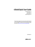
Basic position of the balance wheel (adjustment aid)
Requirement
When the needle bar is positioned at t.d.c., the marking "0" on the scale should be level
with the top edge of the belt guard (see arrow).
2
1
3
2
3
Fig. 1 - 01
● Adjust the scale dial 1 ( depending on model screws 2 or 3 ) in accordance with the requirement.
6
127-01
Adjustment
1.05.02
Balance weight
Requirement
When the needle bar is positioned at b.d.c. (balance wheel position 180°) the largest eccentricity of the balance weight 1 should be at the top.
1
2
2
1
Fig. 1 - 02
● Adjust balance weight 1 (screw 2) in accordance with the requirement.
7
Adjustment
1.05.03
Needle position in the direction of sewing (on the 2571 ME and 2591 ME)
Requirement
With the stitch length set at "5", in its front and rear point of reversal the needle should be
the same distance from the inside edges of the needle hole.
7
5
6
4
=
=
1
2
3
8
Fig. 1 - 03
● Turn on machine and set stitch length to "5".
● Turn machine off and on (synchronise needle bar to stitch length).
● Sew a stitch and check the rear position of the needle according to the requirement.
● Press the stitch control key, sew a stitch and check the forward position of the needle according to the requirement and where necessary make the following adjustments.
● Turn off machine and loosen screws 1, 2 and 3.
● Push the adjusting pin's angled part (Order No. 61-111Snnb641-48 through hole 4
and 5 into the hole 6 of the bearing block 7.
● Move the needle bar frame 8 according to the requirement and tighten screw 1.
● Check according to the requirement.
● Screws 2 and 3 remain loosened for the subsequent adjustment.
8
Adjustment
1.05.04
Needle position in the direction of sewing (on the 2574 ME)
Requirement
The needle must penetrate the middle of the needle hole as viewed in the direction of
sewing.
4
2
3
1
Fig. 1 - 04
● Move the needle bar frame 1 ( screws 2, 3 and 4 ) in accordance with the requirement.
9
Adjustment
1.05.05
Limiting the needle bar frame (Not applicable for PFAFF 2574 ME.)
Requirement
With the stitch length set at "5", when the needle is in its front and rear point of reversal
screw 4 should be the same distance from the inside edge of its hole.
4
2
3
4
1
=
=
Fig. 1 - 05
● Set stitch length to "5".
● Select parameter 605.
● Turn the handwheel in the direction of rotation and check the "requirement".
● If necessary move regulating bow 1 (screw 2 and 3).
10
Adjustment
Preliminary adjustment of the needle height
Requirement
When the needle bar is positioned at t.d.c. (handwheel position 0°) there should be a
gap between upper edge needle bar and upper edge needle pendulum of about 54 mm
(2571/91) or 58 mm. (2574)
1
54 mm (2571 /91
58 mm (2574)
1.05.06
2
Fig. 1 - 06
● Without turning it, re-position needle bar 1 (screw 2) in accordance with the
requirement.
11
Adjustment
1.05.07
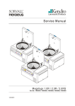
Needle rise, hook clearance, needle height and needle guard (on the PFAFF 2571 ME)
Requirement
With the needle bar positioned 2.0 mm after BDC (balance wheel position 202°) and the
stitch length set at "0.8"
1. the hook point must be at needle centre with a hook-to-needle clearance of 0.05 to 0.1 mm;
2. the top of the needle eye must be 0.8 to 1.0 mm below the hook point;
3. the needle guard 7 must touch the needle lightly.
7
12
6
1
8
4
2
3
9
10 11
5
0,8 - 1 mm
5
Fig. 1 - 07
12
Adjustment
● Set stitch length at "0.8".
● Loosen screws 1, 2, 3, 4 and 5 .
● Select parameter 605.
● Unscrew the needle plate.
● Turn the handwheel four times in the direction of rotation.
● Bring the handwheel into position 202° (= needle bar position 2.0mm after b.d.c.)
● Set the hook point on the middle of the needle. Take care that the needle is not
squeezed by needle guard 7.
● Adjust the needle height according to requirement 2, cf. chapter 1.05.05 Preliminary Adjustment of Needle Height.
● Move hook post according to requirement 1 and tighten screws 4 and 5.
● Move collar 8 into contact and tighten screw 1.
● Move collar 9 into contact and tighten screw 6
● Tighten screws 3 allowing for bevel gear wheel movement.
● Move collar 10 up against bevel gear wheel 11 and tighten screws 2
● Adjust needle guard 7 (screw 12) according to rule 3.
When changing a clamp take care that the
markings 13 and 14 are on one side.
13
14
13
Adjustment
1.05.08
Needle rise, hook clearance, needle height and needle guard (on the PFAFF 2574 ME )
0,8 - 1 mm
Requirement
With the needle bar positioned 2.0 mm after BDC on both hook (balance wheel position
202°) and the stitch length set at "0.8"
1. the hook point must be at needle centre with a hook-to-needle clearance of 0.05 to 0.1 mm;
2. the top of the needle eye must be 0.8 to 1.0 mm below the hook point;
3. the needle guard 9 must touch the needle lightly.
7
9
7
8
14
8
1
2
4
5
3
10
11
12 13
Fig. 1 - 08
● Loosen screws 1, 2, 3, 4, 5, 6 and 7.
● Loosen screws 8 slightly.
● Select parameter 605.
14
6
Adjustment
● Unscrew the needle plate.
● Turn the handwheel four times in the direction of rotation.
● Bring the handwheel into position 202° (= needle bar position 2.0mm after b.d.c.)
● Set both hook points to the centre of the needle, taking care to see that the needles are
not deflected by needle guard 9.
● Set the needle height in accordance with requirement 2, compare Chapter 1.05.05 Preadjusting the needle height.
● Adjust both hook posts in accordance with requirement 1 and tighten screws 8.
● Tighten screws 1 and 6.
● Taking the play of the bevel gear into consideration, tighten screws 3 and 5.
● Move adjustment ring 10 against bevel gear 12 and tighten screws 2.
● Move adjustment ring 12 against bevel gear 13 and tighten screws 4.
● Tighten screws 7 on both sides of the post.
● Adjust needle guard 9 (screw 14) on both hooks in accordance with requirement 3.
When the hook is changed, make sure that markings 15 and
16 are on one side.
15
16
15
Adjustment
1.05.09
Needle rise, Gripper distance, Needle height and Needle guard (on the PFAFF 2591 ME)
0,8 - 1 mm
Requirement
With the needle bar positioned 2.0 mm after BDC (balance wheel position 202°) and the
stitch length set at "0.8"
1. the hook point must be at needle centre with a hook-to-needle clearance of 0.05 to 0.1 mm;
2. the top of the needle eye must be 0.8 to 1.0 mm below the hook point;
3. the needle guard 6 must touch the needle lightly.
6
9
5
1
4
2
3
7
4
8
Fig. 1 - 08
● Set stitch length at "0.8".
● Loosen screws 1, 2, 3, and 4 as well as screw 5 on both sides of the post.
● Select parameter 605.
● Unscrew the needle plate.
● Turn the handwheel four times in the direction of rotation.
● Bring the handwheel into position 202° (= needle bar position 2.0mm after b.d.c.)
● Set the hook point on the middle of the needle. Take care that the needle is not
squeezed by needle guard 6.
● Adjust the needle height according to requirement 2, cf. chapter 1.05.05 Preliminary Adjustment of Needle Height.
● Move hook post according to requirement 1 and tighten screws 4.
16
Adjustment
● Tighten screws 2 allowing for bevel gear wheel movement.
● Move collar 7 up against bevel gear wheel 8 and tighten screws 1.
● Screws 5 remain loosened for further adjustments.
● Adjust needle guard 6 (screw 9) according to requirement 3.
When changing a clamp take care that the
markings 10 and 11 are on one side.
10
11
17
Adjustment
1.05.10
Needle position crosswise to sewing direction (on the PFAFF 2571 ME)
Requirement
As seen crosswise to the sewing direction, the needle must penetrate in the centre of
the needle hole.
2
2
1
3
2
4
2
Fig. 1 - 10
● Turn screws 1 (screws 2, on both sides of the post) according to the requirement.
Ensure that support plate 3 is parallel to hook post 4.
18
Adjustment
1.05.11
Needle position crosswise to sewing direction (on the PFAFF 2574)
Requirement
As seen crosswise to the sewing direction, the needles must penetrate in the centre of
the needle holes.
2
1
2
2
Fig. 1 -10
● Shift bearing plate 1 (screws 2, on both sides of the post) according to the requirement.
19
Adjustment
1.05.12
Needle position crosswise to sewing direction (on the PFAFF 2591 ME)
Requirement
As seen crosswise to the sewing direction, the needle must penetrate in the centre of
the needle hole.
4
3
4
1
4
4
2
Fig. 1 - 11
● Adjust feed wheel post 1 (screws 2, 3 and 4) according to the requirement.
20
Adjustment
1.05.13
Height and stroke of the bobbin case opener
Requirement
1. The top edges of the bobbin case opener 1 and bobbin case base 3 should be on one
level.
2. When the bobbin case opener 1 has deflected the bobbin case to its furthest point,
the catch of the bobbin case should be 0.3 - 0.5 mm from the back edge of the needle
plate recess.
3
1
1
2
0,3 - 0,5 mm
Fig. 1 - 12
● Adjust bobbin case opener 1 (screw 2) in accordance with requirement 1.
● Turn the balance wheel until the bobbin case opener has deflected the bobbin case
to its furthest point.
● Adjust bobbin case opener 1 (screw 2) in accordance with requirement 2.
21
Adjustment
1.05.14
Height of the feed wheel (on the 2571 ME)
0,8 mm
Requirement
1. When pressure is applied to the feed wheel 4, it should protrude from the needle plate
by tooth height (approx. 0.8 mm)
2. When no pressure is applied to the feed wheel 4 , it should have a vertical play of
approx. 0.3 mm.
0,3 mm
4
1
1
2
3
Fig. 1 - 14
● Swing out the roller presser.
● Loosen screws 1 and 2.
● Adjust drive wheel 3 according to requirement 1, taking care to see that the teeth of
drive wheel 3 and feed wheel 4 lock into each other properly.
(Machines of model A have no interlocking).
● Tighten screws 1.
● Adjust guide 5 according to requirement 2 and tighten screws 2.
22
Adjustment
Height of the feed wheel (on the 2574)
0,8 mm
Requirement
1. When pressure is applied to the feed wheel 4, it should protrude from the needle plate
by tooth height (approx. 0.8 mm)
2. When no pressure is applied to the feed wheel 4 , it should have a vertical play of
approx. 0.3 mm.
4
0,3 mm
1.05.15
1
1
2
3
Fig. 1 - 14
● Swing out the roller presser.
● Loosen screws 1 and 2 (two screws each).
● Adjust drive wheel 3 according to requirement 1, taking care to see that the teeth of
drive wheel 3 and feed wheel 4 lock into each other properly.
● Tighten screws 1.
● Adjust guide 5 according to requirement 2 and tighten screws 2.
23
Adjustment
1.05.16
Height of the feed wheel (on the 2591)
0,8 mm
Requirement
The feed wheel should protrude from the needle plate by tooth height (approx. 0.8 mm)
1
2
3
Fig. 1 - 16
● Swing out the roller presser.
● Loosen screws 1.
● Adjust eccentric 3 (fastening screw accessible through hole 2) according to the
requirement.
24
Adjustment
1.05.17
Roller-presser
Requirement
When the roller-presser 1 is resting on the feed wheel 6 it must
1. be parallel to the feed wheel 6 when viewed in the direction of sewing,
2. be in the middle of the (needle when viewed in the direction of sewing and
3. be as close as possible to the needle when viewed in transverse direction of sewing.
3
4
2
8
7
5
6
1
Fig. 1 - 16
● Raise the roller-presser 1.
● Place roller-presser bracket 2 (screws 3) flush to the bottom edge of presser bar 4.
● Always observe requirement 1 when carrying out the following adjustments.
● Move the roller-presser 1 ( screw 5 ) in accordance with requirement 2.
● Allow the roller-presser 1 to come to rest on the feed wheel 6.
● Move bracket 7 (screw 8) according to requirement 3.
When sewing very tight curves the roller-presser 1 should be moved toward
the operator slightly.
25
Adjustment
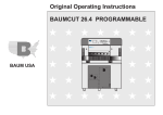
1.05.18
Clearance between roller presser and feed wheel
Requirement
1. With a resting roller-presser there should be a gap between the lift piece 1 and the
housing of about 3mm.
2. With a raised roller-presser the distance between roller-presser and feed wheel should
be 8mm.
4
3
6
1a
5
7
8
3 mm
8 mm
2
1
Fig. 1 - 17
● Set the roller-presser down on the needle plate.
● Decrease roller-presser pressure.
● Adjust lift piece 1 (screws 2) according to the requirement 1.
● Push magnet bracket 3 (screws 4) downwards as far as it will go.
● Raise the roller-presser and place an 8mm gauge under the roller-presser.
● With magnet plunger 5 extended, move lever 6 up against lift piece 1a and mount lever 7
(screws 8) on to magnet plunger 5.
● Check according to the requirement.
26
Adjustment
Knee lever
Requirement
1. When the knee lever is pressed the roller-presser should raise up 7mm
2. Before the roller-presser raises up, the knee lever should have a little bit of clearance.
7 mm
1.05.19
2
1
3
4
Fig. 1 - 18
● Turn screw 1 (nut 2) according to requirement 1 .
● Turn screw 3 (nut 4) according to requirement 2.
27
Adjustment
1.05.20
Tension release
Requirement
With the roller-presser raised the tension shims 3 should be about 0.5mm loosened from
each other.
1
2
0,5 mm
3
Fig. 1 - 19
● Raise roller-presser and calibrate lever 1 (screw 2) according to the requirement.
28
Adjustment
1.05.21
Thread check spring and thread regulator
Requirement
1. The movement of thread regulator 3 must be completed when the needle point enters
the material.
2. When the thread loop is at its largest while being passed around the hook, the check
thread spring 3 should rise slightly from the rest 1.
6
5
2
4
1
3
Fig. 1 - 20
● Position rest 1 (screw 2) in accordance with requirement 1.
● Turn sleeve 4 (screw 2) to adjust the tension of thread check spring 3.
● Position thread regulator 5 (screw 6) in accordance with requirement 2.
For technical reasons it may be necessary to deviate from the indicated spring
stroke or spring tension.
Move thread regulator 5 (screw 6) towards ("+") (= more thread) or ("-") (= less
thread).
29
Adjustment
1.05.22
Bobbin winder
Requirement
1. When the bobbin winder is engaged, the winding spindle must be driven reliably.
When it is disengaged, friction wheel 3 should not be touching drive wheel 1.
2. When it is switched off, the bobbin winder must click securely into its end position
(knife raised).
1
2
Fig. 1 - 22
● Adjust drive wheel 1 (screw 2) in accordance with the requirement.
30
3
Adjustment
1.05.23
Sewing foot pressure
Requirement
1. The material must be fed smoothly.
2. No pressure marks should be visible on the material.
1
Fig. 1 - 23
● Turn adjustment screw 1 in accordance with the requirement.
31
Adjustment
1.05.24
Lubrication
Requirement
After a running time of 10 seconds a fine line of oil should form on a strip of paper held
next to the hook.
1
2
Fig. 1 - 23
● Check whether oil has been filled in and that there is no air in the oil lines.
● Let the machine run for 2-3 min.
While the machine is running do not place hands in the needle or hook area!
Danger of injury from moving parts!
● With the machine running hold a strip of paper 1 on the hook and check the requirement.
● If necessary, adjust the oil flow on screw 2.
32
Adjustment
1.05.25
Re-engaging the slip-clutch
Clutch 1 is adjusted at the works. In the case of a thread jamming, clutch 1 will
disengage, in order to avoid damage to the hooks.
The following describes how to re-engage clutch 1.
1
Fig. 1 - 24
● Remedy jammed thread fault.
● Hold clutch 1 firmly, as shown in Fig. 1 - 19, and turn the balance wheel until clutch 1
re-engages.
33
Adjustment
1.06
Adjusting the edge trimmer -725/04
1.06.01
Position of the knife holder on model 2571
Requirement
When the thread trimmer is engaged and the adjusting wheel has been turned to its highest position
1. the knife holder 2 must be parallel to the post and
2. the top edge of the needle plate must be in the centre of the angular knife opening.
2
1
3
Fig. 1 - 26
● Turn the adjusting wheel 1 to its highest position and engage edge trimmer.
● Adjust knife holder 2 (screw 3) according to the requirements.
34
Adjustment
1.06.02
Position of the knife holder on model 2591
Requirement
When the thread trimmer is engaged, the centre of the angular knife opening must be level
with the top edge of the needle plate.
2
3
1
4
Fig. 1 - 26
● Switch off the machine and engage the edge trimmer.
● Loosen screw 1.
● By turning sccentric 2, position the knife in the centre of its adjustment range.
● Adjust knife holder 3 according to the requirement and tighten screw 1.
● Position locking ring 4 on the knife holder 3.
Depending on the material thickness, changes in the basic setting of eccentric 2
are possible.
35
Adjustment
1.06.03
Knife stroke on model 2571 ME
Requirement
The knife stroke can be adjusted over a range from 1.0 to 3.5 mm, allowing the best possible adaption to all materials used.
1
3
2
3,5
Fig. 1 - 28
● Turn eccentric 1 (screws 2) so that the marking of the desired cutting stroke is opposite
the marking on clamp collar 3.
36
Adjustment
1.06.04
Knife stroke on model 2591 ME
Requirement
The knife stroke can be adjusted over a range from 2.0 to 3.5 mm, allowing the best possible adaption to all materials used.
1
2
3
Fig. 1 - 29
● Adjust crank 1 (nut 2) in slotted lever 3 according to the requirement.
37
Adjustment
1.06.05
Cutting stroke on model 2571 ME
Requirement
When the edge trimmer is engaged and the needle is in the needle hole, the stroke of
knife 1 should be half in front of and half behind the needle, when the motor shaft is turned
by hand.
1
2
1/2
1/2
Fig. 1 - 30
● Switch off the machine and engage the edge trimmer.
● Adjust knife 1 (screw 2) according to the requirement.
38
Adjustment
1.06.06
Cutting stroke on model 2591 ME
Requirement
When the edge trimmer is engaged and the needle is in the needle hole, the stroke of
knife 3 should be half in front of and half behind the needle, when the motor shaft is turned
by hand.
3
1/2
1/2
1
2
Fig. 1 - 31
● Switch off the machine and engage the edge trimmer.
● Adjust knife holder 1 (screw 2) according to the requirement.
39
Adjustment
1.06.07
Knife position
Requirement
When the edge trimmer is engaged, the knife should rest lightly on the needle plate insert,
but no whistling sound should occur during trimming.
2
1
Fig. 1 - 32
PFAFF 2571 ME
● Adjust screw 1 (screw 2) according to the requirements.
● Carry out a cutting test and repeat adjustment if necessary.
PFAFF 2591 ME
● Adjust knife 3 (screw 4) according to the requirements.
● Carry out a cutting test and repeat adjustment if necessary.
40
3
4
Adjustment
1.07
Adjusting the thread trimmer -900/81
1.07.01
Resting position of the roller lever / radial position of the control cam
Requirement
1. When the thread trimmer attachment is at rest lever 7 should fit closely to plunger 5
and the roller on roller lever 4 should be 0.3mm away from control cam 1.
2. When thread lever at t.d.c. (handwheel position 53°) the control cam 1 should have
just bought roller lever 4 to rest.
3
6
0,3 mm
2 1
5
50 mm
9
8
7
4
Fig. 1 - 33
● Create a distance of 50 mm between the highest point of control cam 1 (screws 2) and
collar 3.
● Move collar 4 into contact along control curve 1 and tighten screws 5.
● Turn the handwheel in the direction of rotation until the highest point of control cam 1 is
opposite roller 6.
● Ensure that plunger 7 is at the leftmost position, move magnet 8 (two screws) according
to requirement 1.
● Turn control cam 1 (screws 2) according to requirement 2.
41
Adjustment
1.07.02
Position of the thread catcher holder
Requirement
1. There should be a minimum amount of play between toothed wheel 3 and toothed
segment 4.
2. Both in the neutral position and the foremost position of the catcher, the distance
between the toothed segment 4 and the outer edge of the thread catcher holder 1
should be the same (see arrow).
1
2
1
2
4
4
3
1
4
Fig. 1 - 33
● Adjust the thread catcher holder 1 (screws 2) according to the requirements.
If requirement 2 cannot be fulfilled, loosen screw 2 and move the toothed
segment 4 by one tooth.
42
Adjustment
1.07.03
Distance between thread catcher and needle plate
Requirement
During its swivel movement thread catcher 1 should not pass the edge of the needle
plate (see arrow in magnification).
1
2
2
1
Fig. 1 - 34
● Move thread catcher 1 (screws 2, two screws) parallel to the thread catcher holder in
accordance with the requirement.
43
Adjustment
1.07.04
Position of the thread catcher
Requirement
1. The bottom edge of the thread catcher 1 should be at a distance of 0.1 mm from the
positioning finger of the bobbin case 5.
2. When the thread trimmer is in its neutral position, the rear edge of thread catcher
should be positioned approx. 2.5 - 3 mm behind the edge of the knife.
5
1
3
5-
mm
2,
86-022
0,1 mm
5
3
1
4
2
Fig. 1 - 35
● Move thread catcher 1 (screws 2, two screws) in accordance with requirement 1.
● Turn thread catcher 1 (screw 3) in accordance with requirement 2.
Thread catcher 1 must be parallel to the surface of the thread catcher holder 4.
44
Adjustment
1.07.05
Knife position and knife pressure
Requirement
1. The knife 1 should be touching the needle plate.
2. The knife pressure should be set as low as possible but the cutting operation should
still be carried out reliably.
2
1
Fig. 1 - 36
● Move knife 1 (screws 2) in accordance with requirement 1 or swivel it in accordance
with requirement 2.
45
Adjustment
1.07.06
Bobbin thread retaining spring
Requirement
1. The bobbin thread clamp spring should be guided reliably in the thread groove of the
thread catcher 3.
2. The tension of the bobbin thread spring clamp should be as low as possible, but the bobbin thread should be held reliably after the cutting operation.
3
3
2
1
4
1
Fig. 1 - 37
● Adjust bobbin thread clamp spring 1 (screws 2) in accordance with requirement 1.
● Adjust the tension in accordance with requirement 2 by bending side 4 of the bobbin
thread clamp spring 1.
Control - requirement 1
● Switch off the machine and bring the take-up lever to its b.d.c.
● Engage and disengage the thread catcher 3 by hand and check requirement 1. Adjust if
necessary.
Control - requirement 2
● After the thread has been cut, sew a few stitches by turning the balance wheel, checking
whether the bobbin thread is drawn out of the bobbin thread clamp spring between the
1st and 3rd stitches. If necessary, correct the tension.
46
Adjustment
1.07.07
Manual cutting test
Requirement
1. When thread catcher 1 is on its forward stroke, it must not carry bobbin thread 3 forward too.
2. When thread catcher 1 is in its front position, bobbin thread 3 must be held reliably by
hook 4.
3. After the trimming action, both the needle thread and the bobbin thread must be
perfectly cut and bobbin thread 3 retained.
3
2
1
3
4
Fig. 1 - 38
● Sew a few stitches.
● Turn off the on/off switch.
● Carry out the cutting operation manually.
● Check requirement 1 and 2, and if necessary readjust thread catcher 1 in accordance
with Chapter 1.07.04 Position of the thread catcher.
● Check requirement 3, and if necessary readjust the bobbin thread retaining spring 2 in
accordance with Chapter 1.07.06 Bobbin thread retaining spring.
47
Adjustment
1.07.08
Linkage rod (only for the PFAFF 2574 ME)
Requirement
When the thread trimmer is in its resting position, the drive levers 1 must be parallel.
1
2
1
Fig. 1 - 40
● Adjust drive levers 1 (screws 2) in accordance with the requirement.
48
Adjustment
List of parameters for control P320 / P321
Setting range
Set value
1
101
Pedal controlled start backtack
(I = OFF, II = ON)
I - II
I
102
Reverse rotation (I = OFF, II = ON)
I - II
I
103
Placed stitch (I = OFF, II = ON)
I - II
I
104
Bobbin thread monitoring
(0 = Off, 1 = Counter)
0-1
1
105
Bobbin thread counter
0 - 99999
12000
106
Bobbin thread remaining counter
0 - 999
100
108
Display main processer software version
109
Display step motor processor software version
110
Display control panel software version
111
Display sewing drive component software
Description
Parameter
The operator has free access to the "100" parameters.
Parameters "200" - "800" can only be changed after entering a code number
and many only be changed by authorised personnel.
Group
1.08
version
2
112
Control panel key tone,
(I = OFF, II = ON)
I - II
II
113
Control panel key tone when moving from
one area to another,
(I = OFF, II = ON)
I - II
I
116
Display serial number of machine
-
-
201
Machine configuration
8 = 2571, 2591,
9 = 2571, 2591 with photo cell,
10 = reserved,
11 = reserved,
12 = 2574
13 = 2574 with photo cell
8 - 14
8
49
Parameter
Setting range
Set value
2
202
Roller-presser field discharge (OFF = I, ON = II)
I = roller-presser is lowered slowly.
Should be set for high foot pressure
II = roller-presser is lowered quickly.
Should be set for low foot pressure
I - II
I
203
Single stitch button assignment
1 = Single stitch, 2 = Needle up,
3 = Knee switch
1-3
1
204
Half stitch button assignment
1 = Half stitch, 2 = Needle up,
3 = Knee switch
1-3
1
206
Open thread tension on stop and lift rollerpresser
(I = OFF, II = ON)
I - II
I
207
Open thread tension after trimming and
lift roller-presser
(I = OFF, II = ON)
I - II
I
208
Function of "needle position change" key
I = needle raised without trimming
II = Switch to the next seam section with knee
switch
I - II
I
301
Thread carrier position t.d.c.
2571, 2591
0 - 127
124
2574
0 - 191
1
2571, 2591
0 - 127
16
2574
0 - 191
30
2571, 2591
0 - 127
16
2574
0 - 191
30
2571, 2591
0 - 127
93
2574
0 - 191
83
3
302
303
304
50
Description
Group
Adjustment
Needle position under b.d.c.
Thread trimmer magnet position on
Thread trimmer magnet position pulse
306
307
308
4
Set value
305
Setting range
Parameter
3
2571, 2591
0 - 127
113
2574
0 - 191
173
2571, 2591
0 - 127
93
2574
0 - 191
173
2571, 2591
0 - 127
7
2574
0 - 191
7
2571, 2591
0 - 127
30
2574
0 - 191
160
Description
Group
Adjustment
Thread trimmer magnet position off
Reverse rotation position
Placed stitch position
Thread tension ventilation position
401
Time delay roller-presser lift
0,01s - 1,5s
0,02s
402
Delayed start after lowering roller-presser
0,01s - 1,5s
0,15s
403
Set roller-presser lift
0,01s - 0,2s
0,03s
10 -50%
35%
2571, 2591
100 - 3500
3500
2574
100 - 2600
2600
502
Start backtack speed
100 - 1500
700
503
End backtack speed
100 - 1500
700
504
Soft start speed
100 - 3500
1500
505
Soft start stitch
0 - 15
0
601
Move roller-presser and feed wheel step motor
(must be increased for high foot pressure)
5
6
404
Thread trimmer magnet pulse
501
Maximum speed
51
Set value
8±2
2571, 2591
1 - 50
30
2574
1 - 50
20
Group
Parameter
Description
0 - 127
600
602
Inputs: 0123456789ABCDEF
0 = Needle mid point (E16)
1 = Needle mid point (E15)
2 = Intermittent coding (E14)
3 = Free (E13)
4 = Free (E12)
5 = Free (E11)
6 = Free (E10)
7 = Free (E9)
8 = Emergency button (E8)
9 = Free (E7)
A = Knee switch (E6)
B = Photo cell (E5)
C = Starting inhibitor (E4)
D = Single stitch button on
machine head (E3)
E = Half stitch button on
machine head (E2)
F = Reverse button on
machine head (E1)
603
Machine drive in home position see
set-up-instructions
604
Run cold start
605
Stitch process with step motors by handwheel
606
Display speed control unit value
701
P-section speed regulator
7
52
Setting range
Adjustment
702
I-section speed regulator
0 - 100
50
703
P-section position regulator
1 - 50
20
704
D-section position regulator
1 - 100
30
705
Time for position regulator
0 - 100
25
706
P-section position regulator for remainder brake
1 - 50
25
707
D-section position regulator for remainder brake
1 - 50
15
708
Maximum torque for remainder brake
0 - 100
0
709
Minimum machine speed
3 - 64
6
Set value
35
2574
1 - 26
26
2571, 2591
1 - 35
35
2574
1 - 40
40
712
Positioning speed
3 - 25
18
713
Acceleration ramp
1 - 50
35
714
Braking ramp
1 - 50
30
715
Reference position
2571, 2591
0 - 127
10
2574
0 - 191
35
716
Dead man time
0 - 255
40
717
Motor starting current
3 -10
8
718
Vibration filter
1 -10
6
719
Assign direction of rotation
0-1
0
720
Move positioner
1-2
2
801
Function group 100 access authorisation
(Operator level)
0-1
0
802
Function group 200 access authorisation
(Technician level)
0-1
1
803
Function group 300 access authorisation
(Sewing motor positions)
0-1
1
804
Function group 400 access authorisation (Times)
0-1
1
805
Function group 500 access authorisation
(Counter and revolution speed)
0-1
1
806
Function group 600 access authorisation
(Service)
0-1
1
807
Function group 700 access authorisation
(Sewing motor)
0-1
1
808
Function group 800 access authorisation
(Access authorisation)
0-1
1
809
Programming access authorisation
0-1
1
810
Input access code
0 - 9999
2500
700
710
711
800
Description
1 - 35
Parameter
2571, 2591
Group
Setting range
Adjustment
Maximum machine speed
Maximum motor speed
53
Adjustment
1.09
54
Error Messages and Description
Error
Description
E1
System error
E2
Sewing motor E002/BB/xxx
BB = 20: Deadman
02: Position forwards
03: Position in reverse
05: Position by shortest route
09: Write parameter
10: Speed
0A: Reset stitch counter
0B: Stop after xxx stitches
30: Timeout for increasing speed
31: Timeout from uncertain positioning
32: Timeout from deadman command
33: Timeout for deleting errors
34: Timeout for emergency stop
35: Timeout for writing parameters
36: Timeout for resetting stitch counter
37: Timeout for stop command after x stitches
38: Timeout for initialisation
39: Establishing contact when turned on
xxx = sewing motor control unit error byte (see Motor Errors)
E3
Section
E4
End of section
E5
Pedal or half stitch button or single stitch button (on machine head)
activated when machine turned on
E6
Communication error with the step motor processor
E7
End of ramp
E8
Needle drive end point not found
E9
Needle drive mid-point not found
E 10
Step motor processor error
E 11
Step motor step frequency too high
E 12
Sewing displacement error
E 13
Docu-seam system error
E 14
Incorrect program number (larger than 99)
E 15
Incorrect section number
E 16
Memory full
E 17
Incorrect stitch length
E 18
Unused
E 19
External control interface
E 20
Incorrect control
E 21
Power supply unit overloaded (24V)
E 22
Mains voltage
E 23
Power supply 24V too low
Adjustment
Error
Description
Error in SD-memory card reader
1.10
Error 27 - 1
No SD-memory card inserted
Error 27 - 2
Wrong card (does not match the machine)
Error 27 - 3
Card not inserted correctly
Error 27 - 4
Card with write protection
Error 27 - 5
Data error on SD-memory card
Error 27 - 6
Formatting failed
Error 27 - 7
File does not match the machine
Error 27 - 8
Incorrect file size
Error 27 - 9
Transfer error
Error 27 - 10
Data could not be deleted
Motor Errors
Error
Description
33
Invalid parameter value
35
Communication error
36
Init not ready
37
Command overrun
64
Mains off during initialisation
65
Excess current directly after mains on
66
Short circuit
68
Excess current during operation
70
Motor blocked
71
No incremental plug
74
Incremental transducer missing for transmission/reduction
173
Motor blocked in 1st stitch
175
Interior starting error
222
Dead man monitoring
55
Adjustment
1.11
Updating the machine software via internet
The machine software can be updated with PFAFF flash programming. For this purpose
the PFP boot program (from version 3.25 on) and the appropriate control software for the
machine type must be installed on a PC. The transfer of the data to the machine can be
carried out with a null modem cable (part no. 91-291 998-91) or with an SD-card. The
SD-card must be formatted in the FAT16 format and must not exceed a capacity of
2 GBytes.
The PFP boot program and the control software of the machine type can
be downloaded from the PFAFF-homepage using the following path:
www.pfaff-industrial.de/pfaff/de/partnerweb/downloadsoftware
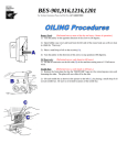
1.11.01
Updating with null modem cable
● After downloading the PFP tool and the control software, open the PFP program.
● Select the machine type and under control unit P321.
● The software version is displayed under report.
2591
P321
Coice:
Machinetype: 2591
Control unit: P321
Softwarenumber: 79-0011-0389/003
--------Coice:
Machinetype: 2591
Control unit: P321
Softwarenumber: 79-0011-0389/003
● Switch off the machine.
● Connect the PC (serial interface or appropriate USB-adapter) and the machine
control unit (RS232). To do so disconnect
the plug of the control panel.
While the machine software is
being updated, no setting up,
maintenance or adjustment
work may be carried out on the
machine!
1
2
Fig. 1 - 27
● Press the "OK" button.
56
● Depending on which software is to be
up-dated, hold down boot key 1 or 2 and
switch on the machine.
1 = for machine controller
2 = for stepping motors
Adjustment
The software update is carried out, the update progress is shown on the bar display of
the PFP boot program.
● During the up-dating procedure the machine must not be switched off.
● When the update has been completed, switch off the machine and end the PFP boot program.
● End the connection between the PC and the machine control unit and reconnect the control panel to the machine control unit.
● Switch on the machine.
A plausibility control is carried out and, if necessary, a cold start.
More information and assistance is at your disposal in the file "PFPHILFE.TXT",
which can be called up from the PFP boot program by pressing the "help" button.
1.11.02
Updating with SD card
● After downloading the PFP tool and the control software, open the PFP program.
● Select the machine type and under control unit SD-CARD.
● The software version is displayed under report.
2591
SD-CARD
Coice:
Machinetype: 2591
Control unit: prepare SD-CARD
Softwarenumber: 79-0011-0389/003
--------Coice:
Machinetype: 2591
Control unit: prepare SD-CARD
Softwarenumber: 79-0011-0389/003
● Under programming copy the software to the drive with the SD-card.
● With the machine switched off insert the SD-card into the control panel.
To update the machine software carry out the following steps:
While the machine software is being updated, no setting up, maintenance or
adjustment work may be carried out on the machine!
57
Adjustment
● witch on the machine, keeping the boot
key 1 pressed.
● Press the "TE" key.
The software update is carried out. During the updating process the diode in the
memory card slot flashes.
● During the updating process the machine
must not be switched off.
● When the update has been completed,
switch off the machine and remove the
SD-card.
1
Fig. 1 - 27
● Switch on the machine
● A plausibility control is carried out and, if
necessary, a cold start.
● To update the step motor software
please contact your PFAFF representative.
More information and assistance is at your disposal in the file "PFPHILFE.TXT",
which can be called up from the PFP boot program by pressing the "help"
button.
58
Circuit diagrams
2
Circuit diagrams
Reference list for the Circuit diagrams 91-191 559-95
A1
PFAFF P 320 / P 321ED Control Device
A2
BDF S3 Control Panel
A14
OTE (Sewing Head Auto Select)
C10
Capacitor for knife drive
DX355
Needle pendulum
H1
Sewing lamp
K10
Relay for knife drive
M1
Sewing motor
M2
Feed wheel step motor
M3
Roller-presser step motor
M4
Needle step motor
M10
Motor edge trimmer
Q1
Main switch
S1
Treadle speed control unit
S10
Switch for edge trimmer
S20
Knee switch
S24
Starting inhibitor button
S41
Hand operation front button
S42
Single stitch button (change needle position)
S43
Thread tension release (FSL)
S44
Automatic presser foot lift (PFA)
T10
Transformer knife drive
X1
Mains plug
X1A
RS232 – control panel interface 1
X1B
VSS OTE
X3
Incremental encoder (sewing motor)
X4A
Feed wheel step motor
X4B
Roller-presser step motor
X5
Inputs
X6A
Needle step motor
X6B
RS232 – interface
X8
Sewing motor
X11A
CAN interface
X11B
Treadle speed control unit
X13
Outputs
Y1
-910/.. PFA
Y2
-900/.. Thread trimmer
Y3
Thread tension release
59
Circuit diagrams
60
Version 18.02.11
91-191 559-95 Part 1
91-191 559-95 Part 2
Version 18.02.11
Circuit diagrams
61
Circuit diagrams
62
Version 18.02.11
91-191 559-95 Part 3
91-191 559-95 Part 4
Version 18.02.11
Circuit diagrams
63
Hans-Geiger-Str. 12 - IG Nord
D-67661 Kaiserslautern
Phone:
+49 - 6301 3205 - 0
Fax:
+49 - 6301 3205 1386
E-mail:
[email protected]
Printed in Germany
© PFAFF Industriesysteme und Maschinen AG 2009, PFAFF is the exclusive trademark of VSM Group AB.PFAFF Industriesysteme und Maschinen AG is an authorized licensee of the PFAFF trademark.
PFAFF Industriesysteme
und Maschinen AG