1
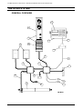
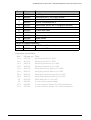
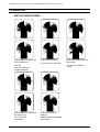
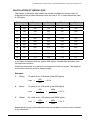
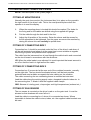
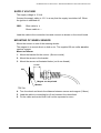
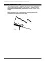
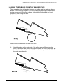
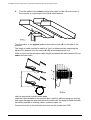
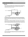
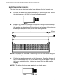
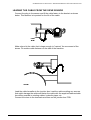
OPERATORS MANUAL &
FITTING INSTRUCTIONS
FOR THE
LH 865 CAPACITY INDICATOR
LH No. 020-865-UK Version 2.00
LH Technologies Denmark ApS
Mølhavevej 2
9440 Aabybro
Denmark
Tel. +45 9696 2500
Fax. +45 9696 2501
Internet: http://www.lh-agro.com/
LH 865 CAPACITY INDICATOR – OPERATORS MANUAL & FITTING INSTRUCTION
We have endeavoured to deliver a fault free product. To ensure optimal use of the
equipment we ask that great attention be paid when reading the manual. We are
more than happy to help should any queries arise, both when the product is used
for the first time and at any later date. Regarding responsibility for use of the
product we refer to our sales and delivery terms especially paragraph 7, which
follows:
7.
Product usage.
7.1
Any use of the product is at the sole risk of the buyer. The
buyer is therefore not entitled to any form for compensation
caused by, for example, any of the following:
Disturbance to/from any electronic services or products that
do not confirm to the standards for CE marking,
Missing or poor signal coverage or a succession hereof from
external transmitters/receivers, used by the buyer,
Functional faults, which apply to or from a PC-program or
PC-equipment, not delivered by the seller,
Faults that may arise from the buyers negligence to react to
warnings and fault messages from the product, or which can
be traced to negligence and/or absent constant control of
the work carried out in comparison to the planned job.
7.2
When implementing any new equipment the buyer must take great
care and pay attention. Any doubts as to correct operation/use
should result in contacting the sellers service department.
This manual may not be altered, copied or manipulated in any way. Unoriginal
manuals can lead to operational faults damaging machines or crops as a
consequence thereof. LH Agro can therefore not be held responsible for damages
incurred, which can be traced to the use of unoriginal or manipulated manuals.
Original manuals can be requisitioned at any time from LH Agro.
LH Technologies Denmark ApS
Mølhavevej 2
9440 Aabybro
Denmark
Tel. +45 9696 2500
Fax. +45 9696 2501
Internet: http://www.lh-agro.com/
2
LH AGRO
LH 865 CAPACITY INDICATOR – OPERATORS MANUAL & FITTING INSTRUCTION
Contents
THE LH 865 SYSTEM .........................................................................................................4
GENERAL OVERVIEW ...............................................................................................4
OPERATING........................................................................................................................6
DISPLAY INDICATIONS .............................................................................................6
CALCULATION OF GRAIN LOSS ..............................................................................7
RULE OF THUMB .......................................................................................................8
SETTING UP THE CAPACITY INDICATOR........................................................................9
FITTING INSTRUCTIONS FOR LH 865 ............................................................................10
FITTING AF MONITOR BOX ....................................................................................10
FITTING OF CONNECTING BOX 1..........................................................................10
FITTING OF CONNECTING BOX 2..........................................................................10
FITTING OF SUN SENSOR......................................................................................10
SUPPLY VOLTAGE ..................................................................................................11
MOUNTING OF WHEEL SENSOR ...........................................................................11
FITTING THE WALKER PADS..........................................................................................12
LEADING THE CABLES FROM THE WALKER PADS.............................................13
FITTING THE SIEVE SENSOR .........................................................................................15
POSITION .................................................................................................................15
SHORTENING THE SENSOR ..................................................................................16
LEADING THE CABLE FROM THE SIEVE SENSOR ..............................................17
NOTES ..............................................................................................................................18
LH AGRO
3
LH 865 CAPACITY INDICATOR – OPERATORS MANUAL & FITTING INSTRUCTION
THE LH 865 SYSTEM
GENERAL OVERVIEW
21
11
1
23
22
12
4
24
6
25
3
2
7
8
10
26
5
4
9
27
LH AGRO
LH 865 CAPACITY INDICATOR – OPERATORS MANUAL & FITTING INSTRUCTION
Pos.:
LH-part no.: Text:
1
908-865
LH 865 grain loss monitor with foot
2
906-865
Connection box 1 for LH 865 system
866-012
Connection box 2 for LH 865 system
900-013
Print for Connection box 2
4
907-012
Straw walker sensor set (2 integration sensors)
5
927-021
Sieve sensor
6
905-865
LH 865 main cable
7
900-708
Sun sensor
8
900-753
Power supply cable
9
900-982
Wheel sensor
10
198-312
Cable for sieve sensor
3
Can be purchased separately:
11
915-865
LH 865 box (without foot)
12
903-865
Foot for LH 865 box
Extension possibilities:
Pos.: LH-part no.: Text:
21 a
901-102
Mounting set for LH 1000.
21 b
901-122
Mounting set for LH 1200.
22 a
843-102
Mounting bracket for LH 1000
22 b
843-122
Mounting bracket for LH 1200
23 a
900-100
Multi plug monitor part for LH 1000
23 b
900-121
Multi plug monitor part for LH 1200
24 a
900-101
Multi plug implement part for LH 1000
24 b
900-120
Multi plug implement part for LH 1200
25
955-122
Multi cable (5m 5 x 0,5 mm2)
26
900-982
2 core sensor (area breaker)
27 a
930-983
3 core revolution sensor 5 m with accessories
27 b
931-983
3 core revolution sensor 10 m with accessories
LH AGRO
5
LH 865 CAPACITY INDICATOR – OPERATORS MANUAL & FITTING INSTRUCTION
OPERATING
DISPLAY INDICATIONS
Both needles in white field
at the same time.
No loss.
Loss over the sieves.
Too much air or blocking.
Too little air under the
sieves.
You can speed up.
(Higher capacity)
6
No or intermittent loss over
the sieves.
Both needles in red field at
the same time.
Loss over the straw
walkers.
Too much loss.
Slow down.
Straw walkers overloaded.
Slow down.
LH AGRO
LH 865 CAPACITY INDICATOR – OPERATORS MANUAL & FITTING INSTRUCTION
CALCULATION OF GRAIN LOSS
The figures in the below table states the number of seeds per current metre of
straw behind the combine harvester when the loss is 1% in a field where the yield
is 400 kg/ha.
Width of cut
Barley
Oats
Wheat
Rye
Cm
25 seeds=1 g
28 seeds=1 g
21 seeds=1 g
25 seeds=1 g
100
100
112
84
100
6’
180
180
201
161
180
8’
240
240
268
201
240
8½’
265
265
296
222
265
10’
300
300
336
252
300
12’
360
360
403
302
360
14’
420
420
470
352
420
15’
450
450
504
378
450
17’
510
510
571
428
510
18’
570
570
638
478
570
Foot
In the table we assume that the yield is 4000 kg/ha. Considerable deviation from
this requires correction.
Collect the lost seeds on a piece of canvas placed under the sieves. The length of
it in the drive direction must be known exactly.
Examples:
1.
Barley
12’ width of cut, 220 seeds (yield 4000 kg/ha).
Loss =
2.
Barley
Wheat
360
= 0,6%
12’ width of cut, 220 seeds (yield 4800 kg/ha).
Loss =
3.
220
220
360
x
4000
4800
= 0,5 %
8½’ width of cut, 200 seeds (yield 5000 kg/ha).
Loss =
200
265
x
4000
5000
= 0,6 %
Seeds that are lying on the field before the harvest shall of course not be included
in the calculation.
LH AGRO
7
LH 865 CAPACITY INDICATOR – OPERATORS MANUAL & FITTING INSTRUCTION
RULE OF THUMB
From the above table it can be concluded that per 1 cm width of cut there may be
1 seed per driven metre.
As the loss usually lays in a 1 metre wide track behind the harvester the lost seeds
cover app. 1 m2.
A normal hand is about 1/100 m2. Acceptable loss therefore will be 1/100 of the
loss stated in the table.
Example:
A combine harvester of 17’ is used in a barley field yielding as stated above.
From the table it appears that acceptable loss (1%) is 510 seeds per metre.
Under the palm of a hand the accepted volume of seeds then will be:
510
100
8
= 5,1 seeds
LH AGRO
LH 865 CAPACITY INDICATOR – OPERATORS MANUAL & FITTING INSTRUCTION
SETTING UP THE CAPACITY INDICATOR
Before putting the monitor into use, it is very important to realise, that not even the
best capacity indicator can prevent grain from being lost.
The purpose of the monitor is to inform the operator about the amount of grain
being lost.
Therefore the monitor must be adjusted as follows:
1.
Adjust the combine harvester as usual to an acceptable loss (without using
the capacity indicator).
NOTE! See the table calculation of grain loss on page 7
2.
After control of the loss, proceed at the same speed.
3.
Adjust the reading of the meters, under the driving, so that the needles are
in the middle of the green area. Use a coin or a screwdriver for the adjusting
screws for sieve and straw walker meters.
NOTE! The adjusting screws can only be turned 270 degrees. Do not use too
much force, or the instrument may be damaged.
OBS! Under very favourable harvest conditions it can occur, that almost no loss is
registered on one or both sensors. Under such conditions the reading of the
meters cannot be adjusted into the green area.
The sensitivity adjustment on the straw walker sensor(s) – NORM-MAX-MIN –shall
only be moved from the NORM position under very special conditions. Only in
cases (special years or crops) where adjustment on the instrument is impossible,
the sensor adjustment can be altered as follows:
NORM
=
normal sensitivity
MAX
=
maximum sensitivity (small seeds)
MIN
=
minimum sensitivity (big seeds)
NOTE! The sieve sensor can be moved in the three slots in the brackets, so that it
is always positioned correct in the loss stream.
To obtain the optimum profit by having a correct adjustment of the capacity
indicator, it is recommended to repeat the above setting up every time you change
field or crop.
After being correctly adjusted the capacity indicator informs the operator, not only
about the amount of loss but also whether the capacity of the combine is fully
utilized or not.
It is recommended to control if the reading of the monitor is in accordance with the
actual loss frequently. Especially when harvesting green and moist crops, as this
may cause the sensors to be coated with a layer of dirt.
This layer must be removed as often as required. Hand cleaner is good for this
purpose.
LH AGRO
9
LH 865 CAPACITY INDICATOR – OPERATORS MANUAL & FITTING INSTRUCTION
FITTING INSTRUCTIONS FOR LH 865
NOTE! See description of the system page 4
FITTING AF MONITOR BOX
Normally the grain loss monitor (the instrument box) is to place on the ground in
the right corner of the driver's cab. This is the most practical place when the
operator is to read the display.
1.
When the mounting place is located this should be marked. The holes for
the fixing and for the cables are drilled using the supplied drill gauge.
2.
Put the cable through the hole and fix the foot.
3.
Adjust the tilt position of the monitor. Raise the sleeve and the screws for
the tilt adjustment to be tightened. Can the upper screws not be reached by
raising the sleeve this can carefully be pulled down.
FITTING OF CONNECTING BOX 1
Connection box 1 should be mounted under the floor of the driver's cab where it
will be well protected and where it at the same time is most suitable as regards
connecting of power and possible extra equipment.
The cable from the instrument box is lead through the cable lead in and connected
on the circuit board in accordance with the directions.
NB! When the cable leads in are adjusted it is most important that exact amount is
cut off so that the lead in is tight around the cable.
FITTING OF CONNECTING BOX 2
Connection box 2 is mounted at the rear end of the combine harvester, normally
on the right side. The box should be situated where it will be best possible
protected and most suitable as regards the later cabling on the combine.
The cable connecting the two connecting boxes is mounted as instructed.
Lead the cable along the existing supply mains, alongside hydraulic tubes etc. to
the connecting box 1. Attach it with the supplied cable clamps.
OBS: Beware of rotating parts, sharp edges and high temperatures (exhaust etc.).
FITTING OF SUN SENSOR
The sun sensor is mounted on the driver's cab or on the grain tank. It must be
situated so that shadows will never fall on it.
Lead the cable to connecting box 1 where it is connected as shown. Where
impossible to fasten the cable to wires, tubes, etc. the supplied cable brackets can
be used.
10
LH AGRO
LH 865 CAPACITY INDICATOR – OPERATORS MANUAL & FITTING INSTRUCTION
SUPPLY VOLTAGE
The supply voltage is 12 Volt.
Connect the supply cable to 12 V in a way that the supply is switched off. When
the ignition is switched off.
OBS:
Blue cable to +
Brown cable to –
Lead the cable to the connection box and connect as shown on the circuit board.
MOUNTING OF WHEEL SENSOR
Mount the sensor on one of the steering wheels.
The magnet is to mount direct on hub or rim. The supplied 20 mm collar must be
used as support.
Mount as follows:
1. Mount the bracket for the censor. (Screw or weld).
2. Mount the sensor in the bracket.
3. Mount the sensor as illustrated below (cut 4 mm thread).
5-8 mm
M4
Magnet can be painted
Washer
4. Turn the wheel and check the distance between sensor and magnet (5-8mm).
5. Lead the cable to connecting box 2 and connect it as described.
6. Fix the cable and control that it will not be squeezed or worn.
LH AGRO
11
LH 865 CAPACITY INDICATOR – OPERATORS MANUAL & FITTING INSTRUCTION
FITTING THE WALKER PADS
The two walker pads must be fitted at the rear of the two outside straw walkers.
Stick the supplied adhesive template on the underside of the walkers with the
arrow pointing to the rear of the walkers and drill the holes as shown on the
template.
NOTE! Remember to take any reinforcements and walker extensions into
consideration when positioning the walker pads.
12
LH AGRO
LH 865 CAPACITY INDICATOR – OPERATORS MANUAL & FITTING INSTRUCTION
LEADING THE CABLES FROM THE WALKER PADS
There must be a loop in the cable between the walker and the machine side as
shown on the following diagram. This loop must be large enough to "capture" the
circular movement of the straw walkers, without affecting the cable too much
(pull/push) when fixing the cable:
Do as follows to determine a suitable loop size:
1.
Attach the cable on the underside of the walker approx. 20 cm from the
point at which the cable comes through the walker, as shown hereunder. Be
careful when attaching the cable fastener as this is important for the life of
the cable (see diagram):
20 cm
LH AGRO
13
LH 865 CAPACITY INDICATOR – OPERATORS MANUAL & FITTING INSTRUCTION
2.
Turn the walker to the lowest position and make a mark (A) on the side of
the machine at a right angle to the fitted cable fastener.
Turn the walker to the highest position and make a mark (B) on the side of the
machine.
The length of cable needed to make the "loop" is determined by measuring the
distance (L) between the two marks (A & B) and multiplying this by 3.
Make a loop from the calculated cable length and attach the cable fastener 20 mm
under the lower mark.
B
B
L
L
A
A
Use this procedure for both walker pads.
Lead the cable hereafter to the junction box. Lead the cable avoiding any sources
that might damage the cable and fasten the cable with the supplied fastener/cable
ties where possible to existing cables, hydraulic pipes, etc.
Connect the wires to the terminals as shown on the junction box PCB.
14
LH AGRO
LH 865 CAPACITY INDICATOR – OPERATORS MANUAL & FITTING INSTRUCTION
FITTING THE SIEVE SENSOR
POSITION
The sieve sensor must be fitted so that it can measure the grain loss behind the
sieves over the whole width of the sieves. The best position for normal grain types
is 120 mm behind the rear edge of the sieves and 50 mm under the sieves
(measured from the centre of the tube).
50 mm
120 mm
The supplied brackets have three slits, when fitting measure from the middle slit.
This allows the sensor to be moved closer to the sieves when harvesting a crop
where not much air is blown under the sieves, i.e. oil seed rape. If the crop being
harvested needs a lot of air to be blown under the sieves the sensor can be moved
further away.
On some machines it might not be possible to fit the sensor in the recommended
position due to, e.g. the adjustment handle. In such cases it may be necessary to
fit the sensor higher or lower than the height given in the above. The centre of the
sensor must not be higher than the sieves or lower than 100 mm under the sieves.
0 mm
100 mm
Once the correct position has been found the brackets can welded or bolted to the
sieves. The point at which the brackets are attached must be stable so that the
sensor does not shake.
LH AGRO
15
LH 865 CAPACITY INDICATOR – OPERATORS MANUAL & FITTING INSTRUCTION
SHORTENING THE SENSOR
The steel tube can be shortened to the length between the two brackets thus:
a.
Remove the rubber bung (opposite the plug) by loosening all nuts. Remove
the plastic spacer in the tube by loosening the allen screw.
b.
Measure the distance (x) between the brackets exactly; reduce this length
by 22 mm. This measurement (L) should be measured from in between the
two washers as shown below. Cut the tube with a hacksaw. As the tube can
be damaged easily avoid using a vice when cutting the tube.
L
22 mm
x
NOTE!
c.
Remember to remove all of the cuttings from the tube before fitting the
rubber bung.
Position the plastic spacer again so that it is approx. 5 mm from the end of
the bolt in the rubber bung. Re-fit the rubber bung so that approx. 5 mm of
the bung is outside the tube. Tighten the nuts so that the rubber swells
slightly.
NOTE!
The bolts in the bung must not touch the plastic spacer.
5 mm
16
LH AGRO
LH 865 CAPACITY INDICATOR – OPERATORS MANUAL & FITTING INSTRUCTION
LEADING THE CABLE FROM THE SIEVE SENSOR
Connect the plug to the sensor and fit the cable fasten to the bracket as shown
below. This fastener is important for the life of the cable.
Make a bend in the cable that is large enough to "capture" the movement of the
sieves. Fit another cable fastener on the side of the machine.
Lead the cable hereafter to the junction box. Lead the cable avoiding any sources
that might damage the cable and fasten the cable with the supplied fastener/cable
ties where possible to existing cables, hydraulic pipes, etc.
Connect the wires to the terminals as shown on the junction box PCB.
LH AGRO
17
LH 865 CAPACITY INDICATOR – OPERATORS MANUAL & FITTING INSTRUCTION
NOTES
18
LH AGRO