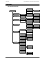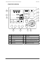
1
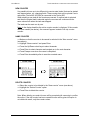
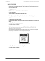
OPERATORS MANUAL FOR THE Teejet 500 SLURRY COMPUTER TeeJet. No. 021-510-UK Version 2.00a Mølhavevej 2 9440 Aabybro Denmark Tel. +45 9696 2500 Fax. +45 9696 2501 www.teejet.com TEEJET 500 SLURRY COMPUTER OPERATORS MANUAL We have endeavoured to deliver a fault free product. To ensure optimal use of the equipment we ask that great attention be paid when reading the manual. Please contact your local dealer if further support is needed. Regarding responsibility for use of the product we refer to our sales and delivery terms especially paragraph 7, which follows: 7. Product usage. 7.1 Any use of the product is at the sole risk of the buyer. The buyer is therefore not entitled to any form for compensation caused by, for example, any of the following: 7.2 Disturbance to/from any electronic services or products that do not confirm to the standards for CE marking, Missing or poor signal coverage or a succession hereof from external transmitters/receivers, used by the buyer, Functional faults, which apply to or from a PC-program or PC-equipment, not delivered by the seller, Faults that may arise from the buyers negligence to react to warnings and fault messages from the product, or which can be traced to negligence and/or absent constant control of the work carried out in comparison to the planned job. When implementing any new equipment the buyer must take great care and pay attention. Any doubts as to correct operation/use should result in contacting the sellers service department. This manual may not be altered, copied or manipulated in any way. Unoriginal manuals can lead to operational faults damaging machines or crops as a consequence thereof. TeeJet Technologies can therefore not be held responsible for damages incurred, which can be traced to the use of unoriginal or manipulated manuals. Original manuals can be requisitioned at any time from your dealer. With regards Mølhavevej 2 9440 Aabybro Denmark Tel. +45 96 96 25 00 Fax. +45 96 96 25 01 www.teejet.com 2 TEEJET 500 SLURRY COMPUTER OPERATORS MANUAL CONTENTS Contents INTRODUCTION ................................................................................................................... 5 OVERVIEW ............................................................................................................................ 6 PROGRAM OVERVIEW ............................................................................................... 6 COMPUTER OVERVIEW ............................................................................................. 7 START/STOP KEY (POS. 1) ...............................................................................................8 AUTO/MAN KEY (POS. 2) ...................................................................................................8 MENU KEY (POS. 3) ...........................................................................................................8 ARROW KEYS (POS. 4) ......................................................................................................8 ENTER KEY (POS. 5) ..........................................................................................................9 ESCAPE KEY (POS. 6) .......................................................................................................9 CLEAR KEY (POS. 7) ..........................................................................................................9 PROGRAM KEYS; THE USER SELECTABLE FUNCTION (POS. 8) .................................9 PROGRAM KEYS; STEP RATE/RATE +/- (POS. 9) ...........................................................9 THE USER SELECTABLE FUNCTION (POS. 10) ..............................................................9 APPLICATION RATE (POS. 11) ........................................................................................10 SPREADER ON/OFF (POS. 12) ........................................................................................10 OPERATION ........................................................................................................................ 11 THE USER SELECTABLE FUNCTIONS .................................................................... 11 WARNINGS ................................................................................................................. 11 SETTINGS ........................................................................................................................... 12 OPERATION SETTINGS ............................................................................................ 12 APPLICATION RATE .........................................................................................................12 WORKING WIDTH .............................................................................................................12 STEP RATE .......................................................................................................................12 WARNINGS .......................................................................................................................13 EMPTY TANK FUNCTION.................................................................................................13 MACHINE SETTINGS ................................................................................................. 14 IMPLEMENT SENSOR ......................................................................................................14 DISTRIBUTOR ...................................................................................................................14 TANK VOLUME .................................................................................................................15 DRIVE FACTOR ................................................................................................................15 RPM SENSOR ...................................................................................................................15 REGULATION TIME ..........................................................................................................15 MANUAL START ...............................................................................................................15 CALIBRATION ............................................................................................................ 16 FLOW METER CALIBRATION ..........................................................................................16 FORWARD SPEED CALIBRATION ..................................................................................17 INFO MENU ......................................................................................................................... 18 TRANSPORT MENU ........................................................................................................... 19 MANUALLY STARTING & STOPPING THE TRANSPORT MENU COUNTERS ...... 20 SHORTCUT TO TRIP COUNTERS ............................................................................ 20 COUNTERS ......................................................................................................................... 21 TRIP COUNTERS ....................................................................................................... 21 NEW COUNTER ................................................................................................................22 NAME COUNTER ..............................................................................................................22 DELETE COUNTER ..........................................................................................................22 3 CONTENTS TEEJET 500 SLURRY COMPUTER OPERATORS MANUAL PRINTING TASKS ...................................................................................................... 23 TOTAL COUNTER ...................................................................................................... 23 SAVE COUNTERS...................................................................................................... 24 SYSTEM .............................................................................................................................. 25 CONTRAST/LIGHT ..................................................................................................... 25 LANGUAGE................................................................................................................. 25 WEIGHT/VOLUME ...................................................................................................... 25 SPEED SIMULATE ..................................................................................................... 25 SOFTWARE INFO ...................................................................................................... 26 TEST ........................................................................................................................... 26 TEST INPUT ......................................................................................................................26 TEST OUTPUT ..................................................................................................................26 DISPLAY APPLICATION RATE PERCENT ............................................................... 27 DEADBAND................................................................................................................. 27 PC COMMUNICATION ............................................................................................... 27 OEM ............................................................................................................................ 28 TOTAL COUNTERS ..........................................................................................................28 UNITS ................................................................................................................................28 NOTES ................................................................................................................................. 29 4 TEEJET 500 SLURRY COMPUTER OPERATORS MANUAL INTRODUCTION INTRODUCTION Thank you for choosing a TeeJet Technologies product. Your new TeeJet 500 Slurry computer is an advanced, but easy to operate product that has been designed to serve you faithfully for many years. Using the computer is simple thanks to the menu based structure. Most settings have a descriptive text shown on the screen, which makes this operator’s manual, more or less redundant – think of this manual as a reference when encoding the various settings. We do however recommend using the manual when sitting in front of the TeeJet 500 Slurry computer before work commences to familiarise yourself with the computer and the how to operate it. All of the settings needed for accurate use are split up into “sub-sections”: Operation settings relate to the settings that change daily. Machine settings relate to the machine and need encoding as a rule only once. The Calibration menu allows you to perform the calibration procedures for correct and accurate operation. The Trip counter function allows for 10 different counter sets to be saved for future reference. The counter sets can be for the work carried out in the field or for transport to and from the field (via the Transport menu). Combining all of the above, plus the ability to apply slurry according to DGPS positions via a serial link with a “VRT” (Variable Rate Treatment) computer, make the TeeJet 500 Slurry computer one of the most versatile, simple to operate slurry spreader computers available on the market today. 5 OVERVIEW TEEJET 500 SLURRY COMPUTER OPERATORS MANUAL OVERVIEW PROGRAM OVERVIEW Application rate Working width Main menu Distributor outlets Step % Operation Settings Operation settings Machine settings Warnings Application rate Empty tank func. Amount left Max. speed Calibration Info Flow meter Speed Implement sensor Distributor speed Distributor Pump speed Tank volume PTO speed Drive factor Transport Trip Counters PTO Regulation time Pump Manuel start Distributor New counter Name counter Print Trip counters Total Save counters Contrast/Light Language System Rpm Sensors Delete counter Print 1 Print 1 – 10 Save HTML Save CSV Weight/Volume Speed simulate Software info Test Test inputs Display rate Pct. Test outputs Deadband PC communication OEM Units Total counter 6 TEEJET 500 SLURRY COMPUTER OPERATORS MANUAL OVERVIEW COMPUTER OVERVIEW 1 12 2 11 0.0 10 0.0 + − XX% XX% Aut/Man T 3 Menu 4 5 Save C 9 8 Pos. Description 7 6 Pos. Description 1 Start/Stop key (Power on/off) 7 Clear key 2 Auto/Man key 8 User selectable function 3 Menu key 9 Step +/- keys; Rate +/- keys 4 Arrow keys 10 The user selected function keys 5 Enter key 11 Application rate 6 Escape key 12 Spreader on/off status 7 OVERVIEW TEEJET 500 SLURRY COMPUTER OPERATORS MANUAL START/STOP KEY (POS. 1) Key Description This key is used to power up/down the Teejet 500 computer. Press this key to start the computer and press and hold for 3 sec. to power down. An info-box will appear to reconfirm the action. When the Teejet 500 computer is running, this key is used to start and stop slurry spreading. When the key is pressed the symbol on the screen (pos. 12) changes depending on the whether the spreader is spreading or not, see page 10. AUTO/MAN KEY (POS. 2) Key Aut/Man Description The AUTO/MAN key is used to change between automatic and manual slurry regulation. ”MAN” is shown in the top left-hand corner of the display when manual regulation is selected. The symbol for the program keys pos. 9 (see page 9) changes depending on the following: Manual regulation: Arrow up (rate increase) and arrow down (rate decrease). Automatic regulation: Step rate in percent with + and –. MENU KEY (POS. 3) Key Menu Description The computer alternates between the operating screen and the main menu each time this key is pressed. The key has a toggle function so if the operating screen is shown and the key is pressed the main menu will be displayed instead and visa versa. If the key is pressed whilst, e.g. encoding, the operating screen will be displayed. ARROW KEYS (POS. 4) Key Description The arrow keys are used to select and alter a setting. The UP and DOWN arrow keys are also used to move the cursor in the operating screen, which allows moving between the 2 selectable operating functions. 8 TEEJET 500 SLURRY COMPUTER OPERATORS MANUAL OVERVIEW ENTER KEY (POS. 5) Key Description The enter key is used to accept settings and to return to the previous screen. ESCAPE KEY (POS. 6) Key Esc Description Use this key to return to the previous menu without saving the value. CLEAR KEY (POS. 7) Key C Description The clear key is used to reset settings/counters and to clear warnings. PROGRAM KEYS; THE USER SELECTABLE FUNCTION (POS. 8) Key Description These 2 keys are used to page through the user selectable functions available in the TeeJet 500 Slurry computer. key 3 - 4 PROGRAM KEYS; STEP RATE/RATE +/- (POS. 9) Key key 1 - 2 Description These 2 keys are used primarily for step rate application in the TeeJet 500 Slurry computer. The size of the steps is encoded under “Operation settings”. The function of these keys changes when alternating between manual and automatic slurry regulation and the symbol above the key changes. The application rate can be increased (arrow up) or decreased (arrow down) when operating with manual slurry regulation. THE USER SELECTABLE FUNCTION (POS. 10) This function is called the user selectable function as the function displayed is selected with the program keys 3 & 4 (pos. 8). A description of the available functions can be seen on page 11. 9 OVERVIEW TEEJET 500 SLURRY COMPUTER OPERATORS MANUAL APPLICATION RATE (POS. 11) The present application rate shown as tons/ha or M3 depending on which rate type is displayed as described on page 25. SPREADER ON/OFF (POS. 12) Symbol Description When this symbol is displayed the spreader is not spreading. Area is not measured as the implement sensor is active. Spreading is started and stopped with the start/stop key (pos. 1). When this symbol is displayed the spreader is spreading. Area is measured. Spreading is started and stopped with the start/stop key (pos. 1). 10 TEEJET 500 SLURRY COMPUTER OPERATORS MANUAL OPERATION OPERATION THE USER SELECTABLE FUNCTIONS Symbol Description Area: The total measured area since the start of the task or since the last reset. See “Trip counter” on page 21. Distance: The driven distance since the last reset (see page 21). The measured distance is displayed in metres up to 9999 m. Hereafter the measure distance is displayed as kilometres (99.99, 999.9, 9999) “Km” instead of “m” is displayed in the symbol when the displayed distance changes to km. Distance measurement is started and stopped by the selected implement sensor so distance is only measured when spreading. Distance can be measured during transport by using the transport menu, see page 19. Forward speed: The present forward speed shown as kilometres per hour. Trip tons: The trip amount spread since the last reset. The procedure for resetting a counter can be seen on page 21 Tons or M3 left: The amount, in tons or M3, remaining in the tank. Distance left: The distance that can be covered with the current tank content. This calculated figure is based on the present volume in the tank, the actual application rate and the current working width WARNINGS Situations can arise that cause a warning to be given under operation. The various warnings can be cancelled by pressing the “C” key. The description and procedure for setting the different warnings can be seen on page 12. The reason for the given warning should be checked thoroughly before cancelling the warning! 11 SETTINGS TEEJET 500 SLURRY COMPUTER OPERATORS MANUAL SETTINGS OPERATION SETTINGS All setting related to daily operation are encoded under the “Operation settings” menu. A description of each menu item follows: APPLICATION RATE Encode the required application rate here in tons per ha or M3 per ha depending on which rate type has been selected as described on page 25. WORKING WIDTH Encode the working width of the used boom, injector, etc. in metres. Key Description Encode the number of outlets that are not used by pressing this key. Note! Select whether the slurry from the outlets that are not used is sent return to the tank or not under “Machine settings” (return on/off, see page 14). STEP RATE Encode the step rate value in percent. This step value is the same for both increasing and decreasing the application rate. The maximum value that can be encoded is 99%. 12 TEEJET 500 SLURRY COMPUTER OPERATORS MANUAL SETTINGS WARNINGS The following audible and visual warnings can be encoded: Key Description Warning on. Warning off. Appl. rate: Warning when the actual rate exceeds the encoded maximum allowed error percent, plus warning on/off. Amount left: Warning when the encoded amount remaining in the tank is reached, plus warning on/off. Max. speed: Warning when the encoded maximum forward speed is reached, plus warning on/off. Rpm distributor: Warning when the encoded minimums distributor speed is reached, plus warning on/off. Rpm pump: Warning when the encoded minimums pump speed is reached, plus warning on/off. Rpm PTO: Warning when the encoded minimums PTO speed is reached, plus warning on /off. We recommend switching off any warnings that are not used. EMPTY TANK FUNCTION It is possible, when using the Empty tank function, to automatically transfer the encoded tank volume into “Ton left”. Each time spreading is stopped, either via the start/stop button or via the selected implement sensor, a pop-up menu is shown from which it is possible to select if the tank is empty. The Empty tank menu is shown when turning at the headland. If the spreader is not empty simply start spreading again and the pop-up menu disappears automatically. When the tank is empty then the encoded tank volume can be transferred automatically to “Ton left” by pressing the ENTER key. The Empty tank pop-up menu can be removed (cancelled) by pressing the C key. Use this for, e.g. encoding different settings, etc. 13 SETTINGS TEEJET 500 SLURRY COMPUTER OPERATORS MANUAL MACHINE SETTINGS All settings that are related to the actual machine are encoded under the “Machine settings” menu. A description of each menu item follows: IMPLEMENT SENSOR This setting is used to select how spreading is started and stopped. The available selections are described in the following: Key Description Start/Stop key: Spreading is started and stopped by pressing the start/stop key. PTO sensor: Spreading is started and stopped when pulses/no pulses are received from a sensor fitted to the PTO axle. Spreading stops when no pulses are received and visa versa. Pump sensor: Spreading is started and stopped when pulses/no pulses are received from a sensor fitted to the pump. Spreading stops when no pulses are received and visa versa. Ext. External sensor: Spreading is started and stopped via signals from an externally fitted sensor. Spreading stops when the sensor is active (input = lo). DISTRIBUTOR The total number of outputs on the distributor plus whether the slurry from the closed outlets is returned to the tank (Returns = ON) or distributed between the other (open) outlets (Returns = OFF) is encoded here. This information is necessary to calculate the total tons spread (Ton +) and the present flow (Ton/min.) if the slurry is returned to the tank after passing through the flow meter from the given number of outputs. The number of outlets that are not used for spreading is encoded under “Operation settings”, which is described on page 12. Returns ON/OFF is changed by moving the cursor over the field and then pressing the ENTER key. 14 TEEJET 500 SLURRY COMPUTER OPERATORS MANUAL SETTINGS TANK VOLUME Encode the slurry spreader tank size in tons or M3 here. This setting is necessary if the “Empty tank” function is to be used (see page 13). DRIVE FACTOR The drive factor expresses the speed at which the regulation system works. If the regulation is too slow then increase the drive factor. If the regulation is too fast (rate jumps up and down) then decrease the drive factor. Standard setting = 25 (as a start figure). RPM SENSOR The number of pulses per revolution must be encoded for the following RPM sensors to ensure that the displayed RPM speed is correct: PTO: The number of pulses per revolution for the rpm sensor fitted to the tractors power take-off shaft (PTO). Pump: The number of pulses per revolution for the rpm sensor fitted to the slurry spreader pump. Distributor: The number of pulses per revolution for the rpm sensor fitted to the distributor. REGULATION TIME Encode the maximum number of seconds that the regulation unit may run when shutting the valve. MANUAL START This function allows spreading to start even if the machine is not moving forwards. This function can be used, e.g. in corners when an area may be missed due to tubes and pipes in the system needing to be filled with slurry. The main slurry valve can be opened using the selected implement sensor, i.e. the start/stop key, for the number of seconds encoded. 15 SETTINGS TEEJET 500 SLURRY COMPUTER OPERATORS MANUAL CALIBRATION The flow meter and the forward speed sensor must be calibrated for correct operation and this is done in the calibration menus. The procedure for these calibrations follows: FLOW METER CALIBRATION Automatic flow meter calibration: The TeeJet 500 Slurry computer has an automatic flow meter calibration function and the procedure for using this is as follows: Step/Key 1 Description If this is the first time that the flow meter is to be calibrated then encode 1000 as the flow figure using the arrow keys. Press this key (program key 1) and encode the amount of slurry in the tank. 2 3 Spread the contents of the tank taking care not to allow air to pass through the flow meter (do not empty the tank completely). Press this key (program key 2) and encode the amount of slurry remaining in the tank (Ton left). 4 Press this key (program key 4) and a new flow figure is calculated automatically by the TeeJet 500 Slurry computer. 5 Manual flow meter calibration: The flow figure can also be calculated manually and the procedure for this is as follows: 1. Fill the slurry tank completely so that the exact amount filled is known. 2. Reset or start a new task (see page 21). 3. Empty the tank completely (avoiding air in the flow meter). 4. Note the amount (Ton) spread under “Trip counter” (see page 21). 5. Place the value in the following formula: NEW FLOW FIGURE = 6. 16 Old flow figure x amount spread Amount displayed (TeeJet 500) Encode the calculated result as the new flow figure. TEEJET 500 SLURRY COMPUTER OPERATORS MANUAL SETTINGS FORWARD SPEED CALIBRATION The forward speed sensor can be selected and the calibration figure is encoded here. It is also possible to calibrate the forward speed sensor and the procedure for this follows: Key Description Using this key (program key 1) selects the radar as the forward speed sensor (via the 7-pin DIN/ISO socket). If the number of pulses per 100 m is known then this can be encoded directly. Using this key (program key 2) selects the wheel sensor fitted to the tractor as the forward speed sensor (via the 7-pin DIN/ISO socket). If the number of pulses per 100 m is known then this can be encoded directly. Using this key (program key 3) selects the wheel sensor fitted to the slurry spreader as the forward speed sensor. If the number of pulses per 100 m is known then this can be encoded directly. Automatic forward speed calibration: Step/Key Description 1 Measure a 100 metre stretch in the field and drive to the start mark. 2 Select the forward speed sensor as described above. 3 4 Press this key and drive the 100 metre stretch. Stop exactly at the stop mark. The TeeJet 500 Slurry computer counts pulses whilst the machine is driving. Press the ENTER key and the calibration procedure is finished. 17 INFO MENU TEEJET 500 SLURRY COMPUTER OPERATORS MANUAL INFO MENU The info. menu displays the following information (use the arrow up/down keys to page): Doserate: The required application rate. The displayed rate will either be the rate that has been encoded or the target rate if the TeeJet 500 Slurry computer is receiving rates via a serial link. PTO: The tractors PTO speed shown as revolutions per minute. Rpm distributor: The distributors speed shown as revolutions per minute. Rpm pump: The slurry spreaders pump speed shown as revolutions per minute. Ton (or M3)/min: Ton (or M3) per minute through the flow meter. Must not be confused with pump capacity. Time: The trip time since the start of the task or since the last reset (see page 21). Ha/hour: The present work efficiency. How large an area is being worked with the present speed and the present working width. Trip counter: The number of the active trip counter set or trip counter name (if encoded) 18 TEEJET 500 SLURRY COMPUTER OPERATORS MANUAL TRANSPORT MENU TRANSPORT MENU The transport menu is used during transport, e.g. from the slurry tank to the field and back again. The following is shown in the display when the transport menu is selected. 14.2 3625 0:45 Aut/Man Menu Esc C Symbol Description Speed: The present forward speed shown in kilometres per hour. Distance: The driven distance since the task was started or since the last reset. The distance counter is started and stopped with the program key 2. Time: The measured time since the task was started or since the last reset. Time measurement is started and stopped with the program key 1. 19 TRANSPORT MENU TEEJET 500 SLURRY COMPUTER OPERATORS MANUAL MANUALLY STARTING & STOPPING THE TRANSPORT MENU COUNTERS The distance and time counters are started and stopped manually in the transport menu and are independent of whether slurry is being spread or not These counters are started and stopped using the program keys 1 & 2. Key Description Time registering on. Time registering off. Distance measurement on. Distance measurement off. SHORTCUT TO TRIP COUNTERS Key Description Pressing the program key under this symbol (program key 4) in the transport menu will open the “Trip counter” menu. This function can be used if, i.e. a new counter set is to be started for transport. 20 TEEJET 500 SLURRY COMPUTER OPERATORS MANUAL DATA/DELETE COUNTERS The Counters menu is selected from the main menu and the following option are available: One of the options can now be selected by using the ARROW UP and ARROW DOWN keys to highlight and then press the ENTER key. To return to the main operating screen press the MENU key. TRIP COUNTERS Amount, Area, Distance and working time information is displayed in this screen and the following options are available for adjustment. The screen to the left is displayed when the “Trip” menu is selected. A description of each individual counter follows: Ton/M3: The total amount spread since the start of the task or since the last reset. Area (Ha): The measured area since the start of the task or since the last reset. The area measured is the effective area, so only the area that has been worked is counted. Distance (m): Distance in metres (effective distance) since the start of the task or since the last reset. Time: The total time used since the start of the task or since the last reset. 21 DATA/DELETE TEEJET 500 SLURRY COMPUTER OPERATORS MANUAL NEW COUNTER It is possible to have up to ten different trip counter sets (tasks) that can be started and stopped when, e.g. changing fields. These counter sets can be printed if an incab printer (TeeJet No. 905-244) is connected to the TeeJet 500. When starting a new task all the counters are zeroed. If another task is selected and then the original task is selected again the counters will continue with the same values from when the task was stopped. The tasks can be reset one by one. Note: In the display headline the active counter number is displayed. If the counter has been named (see below), the name will appear instead of the trip counter number. NAME COUNTER >> Make sure that the counter to be named is selected in the “New counter” menu (see above). >> Highlight “Name counter” and press Enter. >> Press the Up/Down select keys to select character. >> Press Enter to select character and navigate on to the next character. >> Press Escape once when the name is completed. >> Press Enter immediately after to save the encoded name. DELETE COUNTER >> Select the counter to be deleted in the “New counter” menu (see above). >> Highlight the “Delete Counter” option >> Press Enter to delete the counter. Note: When deleting a counter the user will be prompted with a warning to confirm the action. If the trip counter has been named the user will be given the option to not delete the name, only the counter values. 22 TEEJET 500 SLURRY COMPUTER OPERATORS MANUAL DATA/DELETE PRINTING TASKS The active counter set can be printed separately or all ten counter sets can be printed at once. The procedure is thus: 1. Select the main menu (press the MENU key) 2. Highlight “Counters” using the ARROW UP and DOWN keys. 3. Press the ENTER key. 4. Highlight “Print trip counters” using the ARROW UP and DOWN keys. 5. Press the ENTER key. 6. Encode the date that should be printed with the task. 7. Press either FUNCTION key 1 or 2 to print the active counter set. 8. Press either FUNCTION key 3 or 4 to print all counter sets. TOTAL COUNTER Total Amount, Area and time information is displayed in this screen. The counters can not be reset when this menu has been accessed via the “Counters” menu. In order to clear Total counters, the same menu can be accessed via the “OEM” menu (with password) and the clear-key can be used for clearing all counters. The user will be prompted with a warning to reconfirm the action. Ton/M3: The total amount spread or amount spread since the last reset. Area (Ha): The total measured area covered or since the last reset. The area measured is the effective area, so only the area that has been worked is counted. Time: The total time used or time since the last reset. 23 DATA/DELETE TEEJET 500 SLURRY COMPUTER OPERATORS MANUAL SAVE COUNTERS In this menu it is possible to save the Trip Counter and Total Counter values to a file. Saving options are: >> HTML file format. This file format can be viewed in an Internet browser. >> CSV file format. This file format can be viewed in Microsoft Excel. Note: By pressing the Info key, the information above will be displayed as a reminder. >> Select either of the file formats. An info-box will appear, informing that the counters will be saved in the chosen file format. >> Press “Enter” to accept and save, or >> Press “Escape” to cancel. The file will be saved under the name: CNTDATA.HTM or CNTDATA.CSV depending on the selected choice. If the CNTDATA.HTM/CNTDATA.CSV file already exists, an info-box will appear prompting for confirmation for over-writing the existing file. Figure: Overwrite counter data file >> Press “Enter” to over-write the existing file, or >> Press “Escape” to cancel. 24 TEEJET 500 SLURRY COMPUTER OPERATORS MANUAL NOTES SYSTEM The system menu is selected from the main menu (press the MENU key). Use the ARROW UP and ARROW DOWN keys to highlight “System” and press the ENTER key. CONTRAST/LIGHT Key Description Pressing this program key will make the screen lighter. Pressing this program key will make the screen darker. Pressing this program key will activate the auto-light function. The backlight is switched off until a key is pressed, the backlight will be switched on automatically. The display’s backlight is turned on and off with this program key. LANGUAGE The operating language of the TeeJet 500 Slurry computer is selected here. WEIGHT/VOLUME Encode whether the application rate is displayed as ton/ha or M3. If ton/ha is selected then the specific gravity of the slurry must also be encoded. Note: When running the program with US or UK units the Teejet 500 Slurry controller will power down if settings have changed, but only after exit of the “Weight/Volume” menu. This will be prompted with an info-box. SPEED SIMULATE It is possible to simulate a forward speed using this function. Simulating a forward speed can be used for, e.g. testing the system. The speed simulate function is used as follows: 1. Encode the required forward speed that is to be simulated. 2. Press program key 2 to activate the speed simulation function. Note: Speed simulation stops automatically when the first pulse from the speed sensor is received or manually by pressing the program key 2 in the speed simulate menu. 25 NOTES TEEJET 500 SLURRY COMPUTER OPERATORS MANUAL SOFTWARE INFO The current operating software version number for the TeeJet 500 Slurry computer can be seen. TEST TEST INPUT Test input can be used if a sensor is suspected defect Directly under each input description, to the right, is a counter that registers the number of time the input has been activated (the counter is reset automatically each time “Test input” is exited or by pressing the C key). On the left-hand side the actual status of the input is shown (Hi/Lo). All of the different inputs can been seen by pressing the ARROW UP and ARROW DOWN keys to page through the 3 screens. The different input descriptions relate to the following: Input Description Wheel Forward speed signal from the sensor fitted on the tractor (via the 7-pin DIN/ISO socket fitted in the tractor). Radar Forward speed signal from the radar fitted on the tractor (via the 7-pin DIN/ISO socket fitted in the tractor). Wheel implement Forward speed signal from the sensor fitted on the slurry spreader. Press the ARROW DOWN key to see the next inputs: PTO Rpm signal from the sensor fitted to the PTO shaft. Flow Signal from the flow meter. Press the ARROW DOWN key to see the next inputs: Rpm pump Rpm signal from the sensor fitted to the pump. Rpm distributor Rpm signal from the sensor fitted to the distributor. Implement Implement signal (area ON/OFF) from the implement sensor fitted to the tractor (via the 7-pin DIN/ISO socket fitted in the tractor). TEST OUTPUT Each individual output can be tested. Press the program key number for the following test: 26 Output Description Rate + Program key 1 opens the regulation unit. Rate - Program key 2 shuts the regulation unit. TEEJET 500 SLURRY COMPUTER OPERATORS MANUAL DATA/DELETE DISPLAY APPLICATION RATE PERCENT Normally when driving the application rate can be seen to move up and down, this is quite normal. To even out these variances a value can be encoded that represents how much, in percent of the required application rate, the rate displayed can vary from the required (encoded) rate. Example: • The encode rate = 20 t/ha. • The rate displayed varies from 19 to 21 t/ha. • The “Display doserate Percent” is encoded to 5%. • The displayed rate thereafter remains stable at 20 t/ha. DEADBAND Under normal working conditions the Teejet500 program will always try and regulate the distributed slurry in accordance to the current speed, working width and the requested application rate. The regulation constantly monitors the flow and will control the outputs accordingly. This means that the regulation will try and compensate for even the smallest difference between the wanted and the actual application rate. Sometimes this is not optimal since this puts unnecessary strain on the hydraulics that handles the regulation, compared to the effect it has on the actual output. Entering a Deadband percent value will make the regulation stop when the measured application rate is within this percent value of the requested application rate. Example: • The encode rate = 20 t/ha. • The “Deadband” is encoded to 5%. • The regulation (outputs) stops when the measured application rate is within 19 to 20 t/ha. PC COMMUNICATION The Teejet 500 controller is equipped with a serial connection capable of communicating with a PC. This is used by the Super-User customers to transfer files between the Teejet 500 Slurry controller and the PC. File transfers can be used for: • Transferring new languages. • Transferring counter data CNTDATA.HTM and CNTDATA.CSV files. The transfer of data is done with dedicated PC tools. In order to enable the Teejet 500 Slurry controller for PC communication, the controller must be left in this menu (see below). The PC tools will not be able to communicate with the controller if this menu is inactive. 27 NOTES TEEJET 500 SLURRY COMPUTER OPERATORS MANUAL “Memory left” displays the remaining memory of the Teejet 500 Slurry controller for storing data. Figure: PC communication Note: Dedicated PC program and cable are needed to transfer files between Teejet 500 and a PC, special kit can be ordered (Teejet no. 902-399). OEM TOTAL COUNTERS This menu displays a total counter for the amount spread, area covered and total time. To reset counters press the “C” key. An info-box will prompt for the user to reconfirm clearing the total counters. UNITS The Teejet 500 Slurry controller can work with three different sets of units: SI = Metric units US = North American units UK = British imperial units >> Highlight the desired Unit >> Press “Enter” to select the Unit. >> Selected Unit is displayed. Note: When the unit setting is changed the Teejet 500 Slurry controller will power down after exit of the “Units” menu. This will be prompted with an info-box. This is done in order to re-initialize counter settings. 28 TEEJET 500 SLURRY COMPUTER OPERATORS MANUAL DATA/DELETE NOTES OPERATION SETTINGS: Setting SI unit UK/US unit SI unit UK/US unit SI unit UK/US unit Application rate Working width Distributor outlets not used Step% Empty tank function WARNINGS: Setting Application rate Amount remaining Maximum speed Distributor min. RPM Pump min. RPM PTO min. RPM MACHINE SETTINGS: Setting Implement sensor No. of distributor outlets Return to tank Tank volume Drive factor PTO RPM sensor Pump RPM sensor Distributor RPM sensor Regulation time Manuel start 29 NOTES TEEJET 500 SLURRY COMPUTER OPERATORS MANUAL CALIBRATION Setting SI unit UK/US unit SI unit UK/US unit Flow meter Speed sensor Speed sensor Radar Speed sensor Tractor wheel Speed sensor Impl. wheel SYSTEM Setting Weight/volume Weight density Display Appl. Rate percent Deadband 30