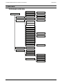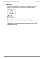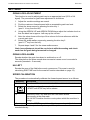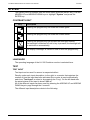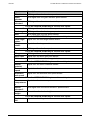
1
OPERATORS MANUAL FOR THE LH 500 COMBINE MONITOR LH. No. 020-522-UK Version 1.00 LH Technologies Denmark ApS Mølhavevej 2 9440 Aabybro Denmark Tel. +45 9696 2500 Fax. +45 9696 2501 Internet: http://www.lh-agro.com/ LH 500 COMBINE MONITOR OPERATORS MANUAL CONTENTS Contents INTRODUCTION .................................................................................................................5 OVERVIEW .........................................................................................................................7 PROGRAM OVERVIEW .............................................................................................7 COMPUTER OVERVIEW............................................................................................8 COMBINE INFO KEY (POS. 1)............................................................................................9 ZOOM KEY (POS. 2) ...........................................................................................................9 MENU KEY (POS. 3) ...........................................................................................................9 ARROW KEYS (POS. 4)......................................................................................................9 ENTER KEY (POS. 5)..........................................................................................................9 ESCAPE KEY (POS. 6) .....................................................................................................10 CLEAR KEY (POS. 7) ........................................................................................................10 FUNCTION KEYS (POS. 8) ...............................................................................................10 SIEVE LOSS INDICATOR BAR (POS. 9)..........................................................................10 GRAIN TANK LEVEL INDICATOR (POS 10) ....................................................................10 WALKER LOSS INDICATOR (POS 11).............................................................................11 REDUCED WORKING WIDTH INDICATOR (POS. 12) ....................................................11 HEADER RAISED INDICATOR (POS. 13) ........................................................................11 FORWARD SPEED INDICATOR (POS. 14)......................................................................11 OPERATION......................................................................................................................13 COMBINE INFORMATION SCREEN........................................................................13 THE USER SELECTABLE FUNCTIONS ..................................................................13 AREA FUNCTIONS ...........................................................................................................13 TIME FUNCTIONS.............................................................................................................14 REDUCED WORKING WIDTH FUNCTION ......................................................................14 WARNINGS...............................................................................................................15 SETTINGS.........................................................................................................................17 GRAIN LOSS ADJUSTMENT ...................................................................................17 GRAIN LOSS ALARM ...............................................................................................17 HA LEFT....................................................................................................................17 SPEED CALIBRATION .............................................................................................17 WORKING WIDTH ....................................................................................................18 HEADER HEIGHT ADJUSTMENT............................................................................18 WARNINGS...............................................................................................................18 DATA/DELETE ..................................................................................................................19 SHOWING THE TRIP AND TOTAL COUNTERS .....................................................19 RESETTING THE TRIP AND TOTAL COUNTERS ..................................................19 SYSTEM ............................................................................................................................21 CONTRAST/LIGHT ...................................................................................................21 LANGUAGE ..............................................................................................................21 TEST .........................................................................................................................21 TEST INPUT ......................................................................................................................21 TEST OUTPUT ..................................................................................................................23 SERVICE MENU .......................................................................................................23 LH AGRO 3 CONTENTS 4 LH 500 COMBINE MONITOR OPERATORS MANUAL LH AGRO LH 500 COMBINE MONITOR OPERATORS MANUAL INTRODUCTION INTRODUCTION Thank you for choosing an LH Agro product. Your new LH 500 Combine monitor is an advanced, but easy to operate product that has been designed to serve you faithfully for many years. Using the monitor is simple thanks to the menu based structure. Most settings have a descriptive text shown on the screen, which makes this operator’s manual, more or less redundant – think of this manual as a reference when encoding the various settings. We do however recommend using the manual when sitting in front of the LH 500 Combine monitor before work commences to familiarise yourself with the computer and the how to operate it. LH AGRO 5 INTRODUCTION LH 500 COMBINE MONITOR OPERATORS MANUAL We have endeavoured to deliver a fault free product. To ensure optimal use of the equipment we ask that great attention be paid when reading the manual. We are more than happy to help should any queries arise, both when the product is used for the first time and at any later date. Regarding responsibility for use of the product we refer to our sales and delivery terms especially paragraph 7, which follows: 7. Product usage. 7.1 Any use of the product is at the sole risk of the buyer. The buyer is therefore not entitled to any form for compensation caused by, for example, any of the following: 7.2 Disturbance to/from any electronic services or products that do not confirm to the standards for CE marking, Missing or poor signal coverage or a succession hereof from external transmitters/receivers, used by the buyer, Functional faults, which apply to or from a PC-program or PC-equipment, not delivered by the seller, Faults that may arise from the buyers negligence to react to warnings and fault messages from the product, or which can be traced to negligence and/or absent constant control of the work carried out in comparison to the planned job. When implementing any new equipment the buyer must take great care and pay attention. Any doubts as to correct operation/use should result in contacting the sellers service department. This manual may not be altered, copied or manipulated in any way. Unoriginal manuals can lead to operational faults damaging machines or crops as a consequence thereof. LH Technologies Denmark ApS can therefore not be held responsible for damages incurred, which can be traced to the use of unoriginal or manipulated manuals. Original manuals can be requisitioned at any time from your dealer. With regards LH Technologies Denmark ApS Mølhavevej 2 9440 Aabybro Denmark Tel. +45 96 96 25 00 Fax. +45 96 96 25 01 Internet: http://www.lh-agro.com/ 6 LH AGRO LH 500 COMBINE MONITOR OPERATORS MANUAL OVERVIEW OVERVIEW PROGRAM OVERVIEW Grain loss adj. Alarm on/off Grain loss alarm Main menu Hectare left Sound delay Encode Operate Speed Auto calibration Encode Working width Header height Chopper Thresher Fan Grain elevator Alarm on/off Return elevator 1 Return elevator 2 Minimum RPM Straw walker Feeder Reel Grain tank Data/Print Data System Contrast/Light Alarm on/off Language Test Test inputs Test outputs Service menu Service counter Program config. LH AGRO 7 OVERVIEW LH 500 COMBINE MONITOR OPERATORS MANUAL COMPUTER OVERVIEW 12 13 14 1 11 10.4 10 2 Km/h 9 3 ½ Menu 4 Esc 5 C 8 Pos. Description 8 7 6 Pos. Description 1 Combine info key 8 User selectable function keys 2 Zoom key 9 Sieve grain loss indicator bar 3 Menu key 10 Grain tank level indicator 4 Arrow keys 11 Walker grain loss indicator bar 5 Enter key 12 Reduced working width indicator 6 Escape key 13 Header raised indicator 7 Clear key 14 Forward speed LH AGRO LH 500 COMBINE MONITOR OPERATORS MANUAL OVERVIEW COMBINE INFO KEY (POS. 1) Key Description Pressing this key displays the combine information screen which is described on page 13. ZOOM KEY (POS. 2) Key Description Pressing the zoom key once will increase the size of the grain loss indicator bars (pos. 9 & 11) for improved readability. Pressing this key again will return to the normal operating screen. When the operating screen is “zoomed” the function keys (pos. 8) are not displayed. MENU KEY (POS. 3) Key Menu Description The computer alternates between the operating screen and the main menu each time this key is pressed. The key has a toggle function so if the operating screen is shown and the key is pressed the main menu will be displayed instead and visa versa. If the key is pressed whilst, e.g. encoding, the operating screen will be displayed. ARROW KEYS (POS. 4) Key Description The arrow keys are used to select and alter a setting. The UP and DOWN arrow keys are also used to move the cursor in the operating screen, which allows moving between the 2 selectable operating functions. ENTER KEY (POS. 5) Key Description The enter key is used to accept settings and to return to the previous screen. LH AGRO 9 OVERVIEW LH 500 COMBINE MONITOR OPERATORS MANUAL ESCAPE KEY (POS. 6) Key Esc Description Use this key to return to the previous menu without saving the value. CLEAR KEY (POS. 7) Key C Description The clear key is used to reset settings/counters and to clear warnings. FUNCTION KEYS (POS. 8) Key key 1 - 4 Description The function of these four keys is shown in the display directly above the key and will change depending on which mode the computer is in (soft-keys). A description of the main operating functions these keys represent can be seen on page 13 SIEVE LOSS INDICATOR BAR (POS. 9) The sieve loss indicator bar shows an indication of grain loss measured by the sensor over the sieves in percent of the calibrated range. The higher the black bar the greater the loss and the lower the black bar the lower the loss. Grain loss over the sieves normally means incorrect fan speed or possible blockages. Make a habit of starting with too much air on the sieves (higher fan speed) as it is easier to reduce the fan speed until the grain loss level is acceptable than it is to increase the fan speed until loss appears. Combine capacity is reduced when the fan speed is too low. GRAIN TANK LEVEL INDICATOR (POS 10) The grain tank level indicator shows, in four steps, how much grain is in the grain tank. 10 LH AGRO LH 500 COMBINE MONITOR OPERATORS MANUAL OVERVIEW WALKER LOSS INDICATOR (POS 11) The walker loss indicator bar shows an indication of grain loss measured by the sensors at the end of the straw walkers in percent of the calibrated range. The higher the black bar the greater the loss and the lower the black bar the lower the loss. Grain loss over the straw walker is normally a matter of the combine harvester being driven too fast. REDUCED WORKING WIDTH INDICATOR (POS. 12) Each time the “reduce working width” function is used (see page 14) an indication of this is shown on the display. HEADER RAISED INDICATOR (POS. 13) When the header is above the set height (see page 18) and area counting is stopped this symbol is shown in the display. FORWARD SPEED INDICATOR (POS. 14) The current forward speed shown in kilometres per hour with one decimal. LH AGRO 11 OVERVIEW 12 LH 500 COMBINE MONITOR OPERATORS MANUAL LH AGRO LH 500 COMBINE MONITOR OPERATORS MANUAL OPERATION OPERATION COMBINE INFORMATION SCREEN When the combine information key is pressed (pos. 1) the following information is displayed: Chopper speed Grain elevator speed Straw walker speed Thresher speed Return elevator 1 speed Feed auger speed Fan speed Return elevator 2 speed Reel speed All of the above speeds are shown as RPM. THE USER SELECTABLE FUNCTIONS Pressing one of the user selectable function keys (pos. 8). The available functions are described in the following: AREA FUNCTIONS Key Description Pressing the Area function key displays the following area functions: Ha/H: The current area being covered per hour. This is calculated from the current working width and present forward speed. Ha: The total measured area since the start of the task or since the last reset. See “Data/Delete” on page 19. Ha-left: The area remaining in the field. This is the encoded area left (see page 17) minus the area covered so far. Pressing any one of the above keys will show the function in the top right-hand side of the display. LH AGRO 13 OVERVIEW LH 500 COMBINE MONITOR OPERATORS MANUAL TIME FUNCTIONS Key Description Pressing the time function key displays the following functions: Start: Pressing this key starts the stopwatch. When the stopwatch is running the time can be seen in the top right-hand corner of the display. The function of this key changes to “Stop” when the stopwatch is running. To stop the stopwatch simply press the “Stop” key. End: Pressing this key displays the time remaining for the current field based on the current working width, present forward speed and the encoded HA Left. This is shown at the top right-hand corner of the display. REDUCED WORKING WIDTH FUNCTION Key Description Each press of this key cycles through the following and changes the reduced working width indicator (pos. 12): 3/4: The encoded working width is reduced by ¼. 1/2: The encoded working width is reduced by ½. 1/4: The encoded working width is reduced by ¾. Press the key once more and the full working width will be used. 14 LH AGRO LH 500 COMBINE MONITOR OPERATORS MANUAL OVERVIEW WARNINGS Situations can arise that cause a warning to be given during operation. An example of a warning given by the system can be seen in the following: The various warnings can be cancelled by pressing the “C” key. The description and procedure for setting the different warnings can be seen on page 18. The reason for the given warning should be checked thoroughly before cancelling the warning! LH AGRO 15 OVERVIEW 16 LH 500 COMBINE MONITOR OPERATORS MANUAL LH AGRO LH 500 COMBINE MONITOR OPERATORS MANUAL SETTINGS SETTINGS GRAIN LOSS ADJUSTMENT This function is used to adjust grain loss to an appropriate level (50% of full signal). The procedure for grain loss adjustment is as follows: 1. Adjust the combine settings as normal. 2. Find the maximum forward speed with an acceptable grain loss level. 3. Select the sieve sensor by pressing function key 1 (pos 8. 1st key from the left). 4. Using the ARROW UP and ARROW DOWN keys adjust the indicator level so that the black bar is approx. half way up the column. 5. Note the value shown at the top of the column for future reference with the current grain type. 6. Select the straw walker sensors by pressing function key 2 (pos 8. 2nd key from the left). 7. Repeat steps 4 and 5 for the straw walker sensor. Grain loss adjustment should be carried out whilst harvesting and check each time the grain being harvested is changed. GRAIN LOSS ALARM Encode whether the grain loss alarm is switched on or off. The delay before the alarm sound when excessive losses occur is encoded in seconds (standard = 5 seconds). HA LEFT Encode the area of the field before work commences. This area is used for calculating END TIME and for the area left function described on page 13). SPEED CALIBRATION The procedure to automatically calibrate the forward speed sensor is as follows: Step/Key 1 Description Measure a 100 metre stretch in the field and drive to the start mark. Press this key from the speed calibration menu. A START and STOP key will be shown. 2 3 Press the START key and drive the 100 metre stretch. Stop exactly at the stop mark. The LH 500 Combine monitor counts pulses whilst the machine is driving. Press the STOP key and the calibration procedure is finished. 4 If the calibration value (number of pulses per 100 m) is known then this can encoded directly. LH AGRO 17 SETTINGS LH 500 COMBINE MONITOR OPERATORS MANUAL WORKING WIDTH Encode the total header width in centimetres. HEADER HEIGHT ADJUSTMENT Raise the header to the height at which area counting should be stopped then press the RETURN key. The current output from the header height sensor is shown in the display during calibration. WARNINGS The following audible and visual warnings can be encoded: Key Description Warning on. Warning off. Chopper: Warning for minimum chopper speed, plus warning on/off. Thresher: Warning for minimum thresher speed, plus warning on/off. Fan: Warning for minimum fan speed, plus warning on/off. Grain elevator: Warning for minimum elevator speed, plus warning on/off. Return elevator 1: Warning for minimum elevator speed, plus warning on/off. Return elevator 2: Warning for minimum elevator speed, plus warning on/off. Straw walker: Warning for minimum walker speed, plus warning on/off. Feed auger: Warning for minimum auger speed, plus warning on/off. Reel: Warning for minimum reel speed, plus warning on/off. Grain tank: Warning on/off for grain tank level. We recommend switching off any warnings that are not used. 18 LH AGRO LH 500 COMBINE MONITOR OPERATORS MANUAL DATA/DELETE DATA/DELETE SHOWING THE TRIP AND TOTAL COUNTERS The following trip and total counters are shown when the DATA/DELETE menu item is selected from the main menu: Time: This trip counter shows the time spent harvesting since the last reset. Hectare (Ha): This trip counter shows the measured area harvested since the last reset. Time Σ: This total counter shows the total time spent harvesting since the last reset Hectare Σ: This total counter shows the total are harvested since the last reset The above counters only measure time & area when machine is harvesting. RESETTING THE TRIP AND TOTAL COUNTERS To reset the trip and total counters simply highlight the counter to be reset and press the C key. LH AGRO 19 DATA/DELETE 20 LH 500 COMBINE MONITOR OPERATORS MANUAL LH AGRO LH 500 COMBINE MONITOR OPERATORS MANUAL SYSTEM SYSTEM The system menu is selected from the main menu (press the MENU key). Use the ARROW UP and ARROW DOWN keys to highlight “System” and press the ENTER key. CONTRAST/LIGHT Key Description Pressing this program key will make the screen lighter. Pressing this program key will make the screen darker. Pressing this program key will activate the auto-light function. The backlight is switched off until a key is pressed, the backlight will be switched on automatically. The display’s backlight is turned on and off with this program key. LANGUAGE The operating language of the LH 500 Combine monitor is selected here. TEST TEST INPUT Test input can be used if a sensor is suspected defect Directly under each input description, to the right, is a counter that registers the number of time the input has been activated (the counter is reset automatically each time “Test input” is exited or by pressing the C key). On the left-hand side the actual status of the input is shown (Hi/Lo). All of the different inputs can been seen by pressing the ARROW UP and ARROW DOWN keys to page through the 6 screens. The different input descriptions relate to the following: LH AGRO 21 SYSTEM LH 500 SLURRY COMPUTER OPERATORS MANUAL Input Description Thresher RPM signal from the thresher speed sensor. Grain elevator RPM signal from the grain elevator speed sensor. Return elevator 1 RPM signal from the return elevator 1 speed sensor. Press the ARROW DOWN key to see the next inputs: Straw walker RPM signal from the straw walker speed sensor. Feed auger RPM signal from the feed auger speed sensor. Reel RPM signal from the reel speed sensor. Press the ARROW DOWN key to see the next inputs: Feed auger status Signal from the feed auger status sensor. Chopper status Signal from the chopper status sensor Fan speed RPM signal from the fan speed sensor. Press the ARROW DOWN key to see the next inputs: Chopper RPM signal from the chopper speed sensor. Sieve loss Signal from the sieve grain loss sensor. Walker loss Signals from the straw walker grain loss sensors. Press the ARROW DOWN key to see the next inputs: Return material Signal from the return materials sensor. Forward speed Signal from the forward speed sensor. Auto/man reel speed Signal from the auto/man reel speed sensor. Press the ARROW DOWN key to see the next inputs: Signal from the straw compartment sensor. Straw compartmen t Return elevator 2 RPM signal from the return elevator 2 speed sensor. Header height Current from the header height sensor. Press the ARROW DOWN key to see the next inputs: Grain tank full 22 Signal from the full grain tank sensor. LH AGRO LH 500 SLURRY COMPUTER OPERATORS MANUAL SYSTEM TEST OUTPUT Each individual output can be tested. Press the program key number for the following test: Output Description 1. Reel Speed + N/A 2. Reel Speed - N/A 3. Tank full The output used to activate an external grain tank full indicator (if fitted). 4. External alarm The output used to activate an external siren when an alarm is given (if fitted). SERVICE MENU The items in this menu are for service use only and are therefore noit described in this operators manual. LH AGRO 23 SYSTEM 24 LH 500 SLURRY COMPUTER OPERATORS MANUAL LH AGRO