1
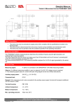
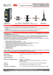
OWNERS MANUAL
MEASURING AMPLIFIER, 4 LIMIT VALUE RELAYS, PULSE TIMER
EVEREST 214
Safety Precautions:
•
•
•
•
•
Installation, initial start-up and maintenance may only be performed by trained personnel! All applicable European and
national regulations regarding installation of electrical equipment must be adhered to.
The device may only be connected to supply power which complies with the specifications included in the technical data
and on the serial plate!
The device must be disconnected from all sources of power during installation and maintenance work!
The device may only be operated under the conditions specified in the operating instructions!
Do not open the housing!
Functions Description:
Measuring amplifier for two sensors with 0/4 to 20 mA signal, 2 or 3-wire connection
•
µ-Processor controlled
•
24 V DC sensor supply power
•
Integrated pulse timer, 1 second to 24 hours, e.g. for MEMPRO ventilation control
•
2 scalable measurement inputs (measured value window)
•
Measurement input E1 or E2 can be individually assigned to each of the output relays, A1 through A4.
•
Adjustable delay time for each limit value relay
•
Adjustable hysteresis for each limit value relay
•
Adjustable filter time of up to 9.9 seconds
•
Selectable Hold-Function for Areation-Controling
•
Normally closed or normally open function can be selected for each limit value relay
Technical Data:
Power Supply:
Power consumption:
Ambient temperature:
Limit value contacts:
Output relay switching capacity:
Housing:
Terminals:
Measuring circuit:
Measuring accuracy:
Display resolution:
Measured value filter:
Reset hysteresis:
Sensor power supply:
Indicators:
Settings:
100V - 255V AC / 50 - 60Hz, oder 10 - 30V DC
1 - 5W
10…+45°C
3+1 floating contacts, 3 with common root, 1 floating contact can be selected as a
clock generator output (can be switched back and forth between NC and NO
function)
250V AC; 3A / 30V DC; 1A Caution: Contacts are not protected against overload –
use external protective device!
22.5 x 100 x 122 mm, IP 40, for Top-hat rail: 35 x 7.5 mm (DIN EN 50 022)
Caution: Contact protection per DIN EN 61010-1 is only assured when installed to
a closed housing with at least IP 54 protection.
Schraubanschluss, max. 1,5mm²
2 Inputs: 4 - 20mA (factory default) scalable 0 - 25mA
better than 1% ±0,5 Digit
1%
Adjustable from 0.1 to 3 seconds
Adjustable from 0 - 99%
24V DC max. 100mA and 5V DC max. 100mA
Measure Value:
2½-place LED 5x7-Dotmatrixdisplay
Switching status:
4x LED yellow = limit value relays
Inputs:
1x LED green = Input 1 and 1x LED blue = Input 2
Rotary switch/pushbutton on the front panel
BAMO IER GmbH Pirnaer Straße 24
68309 Mannheim
Tel. +49 (0)621 84224-0 Fax: +49 (0)621 84224-90 . e-Mail: [email protected] Internet: www.IER.de
SU3534 06/10
1
OWNERS MANUAL
MEASURING AMPLIFIER, 4 LIMIT VALUE RELAYS, PULSE TIMER
EVEREST 214
CE-Mark:
In accordance with low-voltage directive (73/23/ECC), EMC directive (89/336/ECC)
Maintenance:
The device is maintenance-free if used for its intended purpose.
Controls:
Button rotate:
The desired relay (1 through 4) or input (1 through 2) is selected in menu level 1.
The desired values are selected in menu levels 2 through 6.
In menu level 2 - 6 the selected Value ca changed += ritght turn -= left turn
Used to select submenus 1 through 6. Pushing the button in submenu 6
returns the display to menu 1.
If none of the controls are activated for 15 seconds, the device is automatically returned to
the measured value display (menu level 0).
Button push:
Note:
Output relays 1 through 4:
Yellow LED lights up = relay pulled in = contact closed
Limit value:
Setting range from 2 to 100% relative to the selected mA Min-Max range. The limit value can not be set less than or
equal to the actual hysteresis value.
Default setting: A1 = 80%, A2 = 60% A3 = 40% A4* = 20%
Delay time:
Adjustable from 0.1 to 9.9 seconds
Limit value violation wait for delay time to elapse the relay is then switched.
Default setting: 0.1 seconds
Hysteresis:
Setting range: 1 to 99%. The hysteresis value can not be set greater than or equal to the actual limit value.
The output relay is not switched back until the measured value is fallen short of by the selected percentage value.
Default setting: 1%
NC-NO selection:
NO = normally open = contact is open as long as the measured value is less than the selected threshold value
NC = normally closed = contact is closed as long as the measured value is less than the selected threshold value
Default setting: NO
Note: All relays are open in the event of power failure or device malfunction.
Assigning input E1 or E2 to the limit value relay:
The measured value from input E1 or E2 can be assigned individually to each relay output (A1 through A4).
Default setting: E1
Overranging display:
Measuring signal > mA max. value digital display = Measuring signal < mA min. value digital display = BAMO IER GmbH Pirnaer Straße 24
68309 Mannheim
Tel. +49 (0)621 84224-0 Fax: +49 (0)621 84224-90 . e-Mail: [email protected] Internet: www.IER.de
SU3534 06/10
2
OWNERS MANUAL
MEASURING AMPLIFIER, 4 LIMIT VALUE RELAYS, PULSE TIMER
EVEREST 214
Pulse Timer:
The pulse timer is switched on as soon as on and off-time is set to a value of greater than 0.
*Setting values for limit value relay 4 are rendered inactive as a result.
ON-Time
The contact at relay 4 remains closed as long as the selected on-time has not yet elapsed.
Setting range: 1 second to 24 hours
Available setting values:
0*, 1, 2, 5, 10, 30s
No decimal point is illuminated
Example 10 seconds
1, 2, 5, 10, 30min
in the upper middle lane 1 point is blinking
Example 10 minutes
1, 2, 3, 6, 12, 24h
in the upper middle lane 2 points are blinking
Example 12 hours
Default settuing: 0
OFF-Time
The contact at relay 4 remains open as long as the selected off-time has not yet elapsed.
Setting values same as above
Default setting: 0
Note:
After power failure, the device is rebooted and the program starts with on-time.
If on or off-time is changed during operation, the new on or off-time becomes immediately effective.
Scaling Eingang 1 und 2:
mA-Min-value:
Setting range: 0 to 24 mA
Default setting: = 4 mA
mA max. value:
Setting range: 1 to 25 mA
Default setting: = 20 mA
The percentage display can be assigned to a range of the mA measuring signal in the Scaling menu.
25
I/mA
20
Menu Measuring Window Max
100%
15
Input
Signal
Display
10
5
Example:
Measuring signal 5 mA = display of 0%
Measuring signal 18 mA = display of 100%
Settings required to this end:
Menu: Scaling E1 / mA min. = 5
Menu: Scaling E1 / mA max. = 18
0%
Menu Measuring Window Min
0
BAMO IER GmbH Pirnaer Straße 24
68309 Mannheim
Tel. +49 (0)621 84224-0 Fax: +49 (0)621 84224-90 . e-Mail: [email protected] Internet: www.IER.de
SU3534 06/10
3
OWNERS MANUAL
MEASURING AMPLIFIER, 4 LIMIT VALUE RELAYS, PULSE TIMER
EVEREST 214
Filter time:
Filter for attenuating measured value fluctuations and interference
Integration time: adjustable from 0.1 to 9.9 seconds
Default setting: 0.1 seconds
Hold function:
For every Inpute threre can be activate a hold-function. With this feature it is possible to hold the measure value
during the contace of Relay 4 is closed.
Available setting values:
of: hold-function disabled
on: hold-function enabled
The hold-function is not working if one of the timer settings set to 0.
Reset to default settings:
Switch supply power on.
Within 3 seconds (i.e. during the test routine), press and hold the pushbutton for approximately 5 seconds:
The display counts up: 1, 2, 3, 4 ... 99, ST....
All settings are returned to their default values.
Switching on supply power:
After supply power has been switched on, the device starts a test routine during which all LEDs and the digital
display are activated (lamp test). After approximately 1 second, the software version is briefly displayed.
The display is then switched to menu level 0 and the measured value display E1/E2.
Blockdiagramm:
Everest 214
14
16
Power
100 - 250V AC
or 10 - 30V DC
Power Supply
galvanic
isolated
24V / 100mA
4
5V / 100mA
7
0V
2
9
8
10
A1
12
A3
Signalprocessing
Display
13
A4
TX
RX
6
5
E1
1
E2
3
100 Ohm
A2
100 Ohm
11
15
BAMO IER GmbH Pirnaer Straße 24
68309 Mannheim
Tel. +49 (0)621 84224-0 Fax: +49 (0)621 84224-90 . e-Mail: [email protected] Internet: www.IER.de
SU3534 06/10
4
OWNERS MANUAL
MEASURING AMPLIFIER, 4 LIMIT VALUE RELAYS, PULSE TIMER EVEREST 214
Menu:
0
1
2
3
4
5
Measuring Value E1 (%)
Measuring Value E2 (%)
E1
E1
E2
E2
A1
A1
A2
A2
A3
A3
A4
A4
LED On
Switch Push
LED blinking
Selection Relay 1
Selection Relay 2
Selection Relay 3
Selection Relay 4
Selection Pulse Timer
Selection Input 1
Selection Input 2
E1
E1
E1
E1
E1
E1
E1
E2
E2
E2
E2
E2
E2
E2
A1
A1
A1
A1
A1
A1
A1
A2
A2
A2
A2
A2
A2
A2
A3
A3
A3
A3
A3
A3
A3
A4
A4
A4
A4
A4
A4
A4
Limit Value (%)
Limit Value (%)
Limit Value (%)
Limit Value (%)
ON-Time
Measure window min (mA)
Measure window min (mA)
E1
E1
E1
E1
E1
E1
E1
E2
E2
E2
E2
E2
E2
E2
A1
A1
A1
A1
A1
A1
A1
A2
A2
A2
A2
A2
A2
A2
A3
A3
A3
A3
A3
A3
A3
A4
A4
A4
A4
A4
A4
A4
Delay Time (s)
Delay Time (s)
Delay Time (s)
Delay Time (s)
OFF-Time
Measure window max (mA)
Measure window max (mA)
E1
E1
E1
E1
E1
E1
E1
E2
E2
E2
E2
E2
E2
E2
A1
A1
A1
A1
A1
A1
A1
A2
A2
A2
A2
A2
A2
A2
A3
A3
A3
A3
A3
A3
A3
A4
A4
A4
A4
A4
A4
A4
back to
Ebene 1
Hysteresis (%)
Hysteresis (%)
Hysteresis (%)
Hysteresis (%)
Filter Time (s)
Filter Time (s)
E1
E1
E1
E1
E1
E1
E2
E2
E2
E2
E2
E2
A1
A1
A1
A1
A1
A1
A2
A2
A2
A2
A2
A2
A3
A3
A3
A3
A3
A3
A4
A4
A4
A4
A4
A4
NO/NC Selection
NO/NC Selection
NO/NC Selection
NO/NC Selection
Hold Function
Hold Function
E1
E1
E1
E1
E1
E1
E2
E2
E2
E2
E2
E2
A1
A1
A1
A1
A1
A1
A2
A2
A2
A2
A2
A2
A3
A3
A3
A3
A3
A3
A4
A4
A4
A4
A4
Normally Open
Normally Open
Normally Closed
6
LED off
Switch Turn
Normally Open
Normally Closed
Normally Closed
Assign E1 or E2
Assign E1 or E2
Assign E1 or E2
E1
E1
E1
E1
E2
E2
E2
E2
A1
A1
A1
A1
A2
A2
A2
A2
A3
A3
A3
A3
A4
back to
Level 1
Relay 1
A4
back to
Level 1
Relay 2
A4
back to
Level 1
back to
Level 1
Normally Closed
Assign E1 or E2
A4
A4
Normally Open
back to
Level 1
Relay 4
oder
Pulse Timer
Input 1
back to
Level 1
Input 2
Relay 3
BAMO IER GmbH Pirnaer Straße 24
68309 Mannheim
Tel. +49 (0)621 84224-0 Fax: +49 (0)621 84224-90 . e-Mail: [email protected] Internet: www.IER.de
SU3534 05/11
5
OWNERS MANUAL
MEASURING AMPLIFIER, 4 LIMIT VALUE RELAYS, PULSE TIMER EVEREST 214
Elektrischer Anschluss:
Sensor 1
4-wire connection
external Power Supply
internal Current Source
L
Sensor 2
in 2-wire connection
Sensor 1
in 2-wire connection
24V DC
24V DC
N
L
4 - 20mA
Sensor 2 (e.g. Turbicube)
4-wire connection
Power Supply from Everest
internal Current Sink
N
24V DC
24V DC
4 - 20mA
4 - 20mA
4 - 20mA
Fuse
Fuse
16
14
1
2
E1
Power
Supply
3
0V
4
16
E2
100
Ohm
14
2
E1
Power
Supply
100
Ohm
1
3
0V
4
E2
100
Ohm
100
Ohm
+24V
+24V
Everest 214
Everest 214
Interface for
Datalogger/Digital Sensor
A1
9
10
A2
11
A3
12
A4
13
15
RX
5
TX
6
+5V
OC
7
8
Control and
Indication Decive
Interface for
Datalogger/Digital Sensor
A1
9
10
A2
11
A3
12
A4
13
15
Control and
Indication Decive
Sample schematic for sensors with 2, 3 or 4-wire connection
BAMO IER GmbH Pirnaer Straße 24
68309 Mannheim
Tel. +49 (0)621 84224-0 Fax: +49 (0)621 84224-90 . e-Mail: [email protected] Internet: www.IER.de
SU3534 05/11
6
RX
5
TX
6
+5V
OC
7
8