1
2.
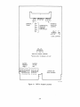
Connect the female Berg connector on the BC26L-25 cable to J 1 on the M8020 module t
and plug the module into a dual LSI-II bus slot of the backplane.
CAUTION
Insert and remove modules slowly and carefully to
avoid snagging module components on the card
guides.
3.
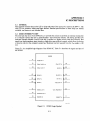
Connect the H3259t turn-around connector to the EIA connection on the BC26L-25 cable.
The jumper WI on the H3259 turn-around connector must be removed.
4.
Perform resistance checks from backplane pin AA2 (+ 5 Y) to ground and from AD2 (+ 12
Y) to ground to ensure that there are no shorts on the M8020 module or backplane.
5.
Turn system power on.
6.
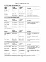
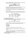
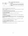
Check the voltages to ensure that they are within the specified tolerances (Table 2-4). If
voltages are not within specified tolerances, replace the associated regulator (H780 P.S.)
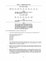
Table 2-4
Voltage Requirements
Voltage
Max.
Min.
Backplane Pin
+5V
+I2Y
+5.25
12.75
+4.75
+ 11.25
AA2
AD2
2.4.1 Verification of Hardware Operation
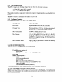
The M8020 module is now ready to be tested by running the CYDPY* diagnostic. Additional information on the DPVII diagnostics is contained in Appendix A. Proceed as follows.
NOTE
The • represents the revision level of the diagnostic.
1.
Load and run CVDPV·. Three consecutive error-free passes of this test is the minimum requirement for a successful run. If this cannot be achieved, check the following.
Board seating
Jumper connections
Cable connection
Test connector
If a successful run is still unachievable, corrective maintenance is required.
2.
Load and run the DEC/XII System Exerciser configured to test the number of DPYlis in
the system.
Each DEC/XII CXDPV module will test up to eight consecutively addressed DPYlls.
CXDPY uses a software switch register. Refer to the DEC/Xii Cross-Reference (ASF055e-MC) for switch register utilization.
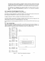
t If a BC26L-25 cable and H3259 tum-around connector are not available, an on-board test connector (H3260) can be ordered separately. See Paragraph 2.5.
2-7