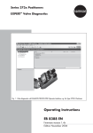
1
Series 3730
Electropneumatic Positioner
Type 3730-3
ESD Version
®
With HART communication
Fig. 1 · ESD mode in SAMSON TROVIS-VIEW 3 software
Mounting and
Operating Instructions
EB 8388-1 EN
Firmware version 1.4x
Edition November 2006
Contents
Contents
1
1.1
1.2
1.3
1.3.1
1.3.2
1.3.3
Description. . . . . . . . . . .
General . . . . . . . . . . . .
ESD functions . . . . . . . . .
Presetting the positioner. . . . .
Converting TROVIS-VIEW 3. . .
Unlocking the positioner . . . .
Printing the diagnostic/ESD log .
2
2.1
2.1.1
2.2
2.2.1
2.3
2.4
2.5
ESD functions . . . . . . . . . . . . . . . . . . . . . . . . . . . . . 8
Changing ESD parameters and starting the partial stroke test . . . . . . 12
On-site operation . . . . . . . . . . . . . . . . . . . . . . . . . . . 13
Analyzing measured data . . . . . . . . . . . . . . . . . . . . . . . 13
Condensed state/Fault alarm output . . . . . . . . . . . . . . . . . . 14
Measured data . . . . . . . . . . . . . . . . . . . . . . . . . . . . 15
Resetting ESD . . . . . . . . . . . . . . . . . . . . . . . . . . . . . 15
List of ESD parameters. . . . . . . . . . . . . . . . . . . . . . . . . 16
3
EXPERT test functions . . . . . . . . . . . . . . . . . . . . . . . . . 19
4
Notes on applications. . . . . . . . . . . . . . . . . . . . . . . . . 20
2
.
.
.
.
.
.
.
.
.
.
.
.
.
.
.
.
.
.
.
.
.
.
.
.
.
.
.
.
.
.
.
.
.
.
.
.
.
.
.
.
.
.
.
.
.
.
.
.
.
.
.
.
.
.
.
.
.
.
.
.
.
.
.
.
.
.
.
.
.
.
.
.
.
.
.
.
.
.
.
.
.
.
.
.
.
.
.
.
.
.
.
.
.
.
.
.
.
.
.
.
.
.
.
.
.
.
.
.
.
.
.
.
.
.
.
.
.
.
.
.
.
.
.
.
.
.
.
.
.
.
.
.
.
.
.
.
.
.
.
.
3
3
4
5
5
6
7
+
EB 8388-1 EN
Description
1
Description
The Type 3730-3 Positioner in ESD version
is based on the Type 3730-3 Positioner with
HART® Communication.
These mounting and operating instructions,
EB 8388-1 EN, supplement EB 8384-3 EN
and focus on the ESD functions.
Technical data, attachment, electrical and
pneumatic connections as well as operation
and the standard EXPERT valve diagnostics
are dealt with in Mounting and Operating
Instructions EB 8384-3 EN.
Note!
The optional external position sensor cannot
be used with the Type 3730-3 Positioner in
ESD version.
Extended EXPERT+ valve diagnostics are described in EB 8388 EN. By default, all
positioners in ESD version include the
EXPERT+ valve diagnostic functions.
Note!
Positioners delivered not mounted on an actuator are configured with the default settings, which means that the ESD functions
are not activated.
After mounting the positioner on a safety
shut-off valve and starting it up, switch the
positioner to ESD mode to allow it to perform the safety functions (for required settings and instructions, see section 2 and
EB 8384-3 EN).
1.1
General
Note!
When the ESD function is active, the
positioner keeps the attached valve to a set
position, e.g. open. The valve does not perform any control tasks anymore.
In AUTO operating mode, the positioner
can be used to control the attached valve.
ESD (Emergency ShutDown) is a positioner
function with extended firmware and partial
stroke testing for the predictive, status-oriented detection of malfunctions in pneumatic
shut-off valves in safety instrumented systems
(SIS).
As a result, the probability of failure on demand (PFD) can be reduced and maintenance intervals can be extended.
All testing and diagnostic functions are completely integrated into the positioner. The
measured data and test results are collected
and stored in the positioner.
Partial stroke tests can be started and cancelled either manually at any time (on site or
using an engineering tool) or automatically
according to a certain schedule.
A test status is determined at the end of a
partial stroke test, which allows operators to
directly see whether the test has been completed successfully or not. When the test has
not been completed successfully, possible
causes of the fault are given. Apart from being indicated on the positioner’s display or
in the engineering tool used, the test status is
also issued at the fault alarm output.
EB 8388-1 EN
3
Description
Operation
Partial stroke test
The positioner can be operated on site using
the rotary pushbutton (see section 2.1.1
“On-site operation“). Alarms are indicated
on the LCD and issued over the fault alarm
output (condensed status).
The partial stroke test integrated into the
positioner can prevent a normally open
valve or a valve in its end position from
seizing up or getting jammed.
The TROVIS-VIEW 3 software allows for
convenient operation when communicating
through the SAMSON SSP interface protocol. Thanks to DD and the FDT/DTM concept, the ESD functions can easily be integrated into the process control system or asset management system.
The instructions concerning operation in the
following sections refer to operation with
TROVIS-VIEW 3.
Note! All parameter settings entered in the
user interface need to be downloaded to the
positioner to become effective.
1.2
ESD functions
ESD mode
In ESD mode, the safety shut-off valve is
moved to a specific set point within its working range. The valve does not perform any
control tasks anymore. The valve is fully
closed in case of an emergency.
In its basic setting, the positioner behaves
similar to a solenoid valve, which keeps the
attached valve to a set position, e.g. open.
For test purposes, the partial stroke test can
either be started manually (ESD Man) or
triggered automatically according to schedule (ESD Auto).
4
EB 8388-1 EN
As the course of the partial stroke test is
plotted, the dynamic control response can
also be analyzed.
During the test, the valve is moved out of the
end position or from a start value either in
steps or in a ramp function until it reaches a
defined final value. Then, the valve is moved
back again to its initial position.
The partial stroke test is performed, for example between 10 and 15 % of the rated
travel, starting from the end position while
the plant is running, yet without disrupting
plant operation. The start and stop values
for the partial stroke test can be configured
by the user.
The following test cancellation conditions
provide additional protection against the
valve slamming shut and moving past the final value:
4 Valve position x
4 Drive signal y
4 Maximum test time is exceeded
4 Tolerance range exceeded
The course of the controlled variable x, reference variable w, setpoint deviation e, and
drive signal y parameters is saved in the
positioner, assigned to the operating hours
counter.
The dead time, T63, T98, overshooting, rise
time, and response time parameters of a
step response test are analyzed separately
Description
for the increasing and decreasing characteristic.
1.3
The analyses of the last three partial stroke
tests are saved in the positioner with the associated time stamp.
1.3.1 Converting TROVIS-VIEW 3
The EXPERT+ test functions Data logger and
Hysteresis test to detect friction changes are
also available in ESD mode (see section 3
and EB 8388 EN).
Note!
The valve position is used as the valve travel
condition by the data logger of positioners
in ESD version.
Presetting the positioner
The TROVIS-VIEW 3 version must match the
software version of the positioner.
When establishing communication or exchanging data between the PC and the
positioner, the firmware version is checked
automatically and the appropriate
TROVIS-VIEW 3 module is loaded.
To adapt the TROVIS-VIEW 3 version before
transmitting data proceed as follows:
1. In the File menu, select Convert.
A window listing all available firmware
versions is opened.
2. Select “Version 1.xx-1.xx ESD”.
3. Confirm selection with OK.
TROVIS-VIEW 3 switches to the user interface for the positioner in ESD version.
EB 8388-1 EN
5
Description
1.3.2 Unlocking the positioner
To prevent unauthorized access, the
positioner settings cannot be changed unless
the valid ESD code has been entered.
The positioner needs to be unlocked separately for on-site operation and operation
through TROVIS-VIEW depending on the
operating mode.
Entering the code in TROVIS-VIEW 3
1. In the Device menu, select ESD enabling
code.
TROVIS-VIEW 3 establishes a connection with the positioner.
2. Enter the code in the Value field.
The ESD code can be found on page 21.
Remove the code or make it unreadable to
prevent unauthorized use.
Entering the code on the positioner
Default: OFF
Turn
→ Code 3
Press
.
→ ON
Turn
Press
→ ESD code
Turn
Press
6
. Display shows: 0
. Display shows: ON,
EB 8388-1 EN
3. Confirm selection with OK.
Description
1.3.3 Printing the diagnostic/ESD
log
The Print command allows you to print out a
diagnostic log of individual tests or the entire diagnosis.
the context-sensitive menu to print the diagnostic log.
The printout contains the contents of the
folder and its subfolders.
The diagnostic log includes a title page and
a list of all the data points including all their
values and properties.
The title page contains all key information
for clear identification of the printed log (device type, file name, time and date of creation, time and date of the last change and
TROVIS-VIEW version).
Select Print in the File menu to add further
information.
1. In the File menu, select Print Options to
choose the scope of the diagnostic log.
After installing/updating the
TROVIS-VIEW software, customer data
(Customer data in the Edit menu) and
summary (table of contents) are listed in
the diagnostic log by default.
Check the check boxes for the Comments
and Graphics options to add these options to the diagnostic log.
2. Right-click the [Diagnosis] folder or the
required subfolder and select Print from
EB 8388-1 EN
7
ESD functions
2
ESD functions
TROVIS-VIEW 3: [Diagnosis > Emergency
Shut Down]
In TROVIS-VIEW 3, the functions of the
positioner in ESD mode are listed in the
[Diagnosis] folder under Emergency Shut
Down. They include:
Activating/deactivating ESD mode and
starting the partial stroke test
Setting the parameters for partial stroke
testing
Defining the cancellation conditions for
partial stroke testing
4
4
4
Note!
Instructions on how to change parameters
and start the partial stroke test can be found
in section 2.1 “Changing ESD parameters
and starting the partial stroke test“.
ESD mode
ESD mode is active if the Target mode parameter in the [Positioner] folder under Operating mode is set to “Emergency Shut
Down“ and Desired ESD mode parameter in
the [Diagnosis] folder under Emergency Shut
Down is set to “On“.
8
EB 8388-1 EN
In ESD mode, the safety shut-off valve is
specifically moved to the set point of the
valve working range (parameter: Required
manual reference variable w).
The positioner behaves similar to a solenoid
valve, which keeps the attached valve to a
set position, e.g. open. The valve does not
perform any control tasks anymore.
The current valve position is indicated under
Manual reference variable w.
The ESD operating mode parameter sets the
conditions for starting the partial stroke test:
Test started manually (ESD Man)
ESD operating mode parameter = ESD Man
Partial stroke testing begins when triggered
by the Start step response parameter. Otherwise, the valve remains in the position defined by the Required manual reference
variable w parameter.
Changes to the parameters can only be
made in ESD Man mode.
ESD functions
Test started automatically according to
schedule (ESD Auto)
ESD operating mode parameter = “ESD
Auto“
Partial stroke tests are conducted at regular
intervals. The Time until the next automatic
ESD test parameter indicates when the next
test is scheduled (countdown).
Partial stroke test
The course of the partial stroke test depends
on the parameters listed under Settings in
TROVIS-VIEW 3. Depending on the parameter settings, the partial stroke test is conducted either in steps or in a ramp function
of the valve position (see Fig. 2).
After being triggered, the test does not start
until the Settling time before test start (t1) has
elapsed. This waiting period ensures that the
valve has reached the position defined by
the Step start parameter (pos. 2, see Fig. 2)
before the test starts.
Starting from the Step start position (pos. 2),
the valve moves to the defined end position
(Step end parameter, pos. 3). The valve remains in this position for the time defined by
the Delay time after step (t2) before performing a second step change in the opposite direction from Step end (pos. 3) to Step start
(pos. 2).
After the Delay time after step (t2) has
elapsed, the valve is moved back to its initial
position (= Required manual reference variable w, pos. 1)
The Step tolerance limit (range: 0.1 to
10.0 %) sets the permissible tolerance limit
for the step’s start and end values.
The Scan rate (range: 0.2 to 30.0 s) defines
the interval at which the measured values
are recorded during the test. The positioner
stores a maximum of 100 measured values
per measured variable (valve position x, reference variable w, setpoint deviation e,
drive signal y and the time when they were
recorded). After 100 measured values per
EB 8388-1 EN
9
ESD functions
2. Ramp function, Fig. 2 right
The ramp function is active when the Activation of the ramp function parameter is set to
"On".
measured variable have been stored, the
logging is stopped. However, the test is still
completed. The Measured data storage out
of memory alarm is generated. The Recommended sampling time, which should not be
shorter, if at all possible, is calculated from
the Duration of the test.
Note!
A step before the partial stroke test can be
prevented by allocating the value of the
manual reference variable w to the Step
start parameter.
The Display section in TROVIS-VIEW 3
shows the Progress flag in percent.
1. Step response function, Fig. 2 left
The step response function is activated when
the Activation of the ramp function parameter is set to "Off".
The valve is moved in steps to the Step end
position (pos. 3) during the first half of the
test and to the Step start position (pos. 2)
during the second half of the test.
w
Step response
[%]
The valve is moved to the Step end (pos. 3)
and Step start (pos. 2) positions with fixed
velocities (v1 and v2) set by the Ramp time
(falling) and Ramp time (rising) parameters.
w
Pos. 1
Pos. 1
Pos. 2
Pos. 2
Pos. 3
Pos. 3
Ramp function
[%]
v1
v2
t
t1
t2
Valve positions:
Pos. 1 = Required manual
reference variable w
Pos. 2 = Step start
Pos. 3 = Step end
t2
[s]
t
t1
Times:
t1 = Settling time before test start
t2 = Delay time after step
t2
Velocities:
100
%
Ramp time (falling) s
100
%
v2 =
Ramp time (rising) s
v1 =
Fig. 2 · Courses of the partial stroke tests with step response (left) and ramp function (right)
10
EB 8388-1 EN
t2
[s]
ESD functions
The ramp time specifies the time required by
the valve to move through the travel range
100 to 0 % (falling) and 0 to 100 % (rising).
4
Note!
Times for the Ramp time (falling/rising) are
determined during initialization of the
positioner. These times are not to be exceeded when setting the parameters for the
partial stroke test with ramp function.
Cancellation conditions
To ensure that the running process is not disrupted and that the shut-off valve does not
slam shut unintentionally, it is advisable to
define conditions that cause the positioner to
cancel an active partial stroke test. The
positioner issues an alarm when a test has
been cancelled (see section 2.2).
Possible cancellation conditions are:
Max. test duration: The test is cancelled
when the maximum permissible test duration (range: 30.0 to 3000.0 s) is exceeded.
x control value: The test is cancelled
when the value falls below the adjusted
valve position (range: –10 to 110 %).
4
4
4
The condition is only active when Activation x control is set to “On“.
y control value: The test is cancelled
when the value falls below the adjusted
drive signal (range: 0 to 9999 1/s).
The condition is only active when Activation y control is set to “On“.
Monitoring the drive signal y only makes
sense when the partial stroke test is performed as a ramp function because the
y cancellation condition is always met
with the step response function.
A suitable y control value can be determined using the last performed partial
stroke test. After the test is completed, the
lowest drive signal value recorded by the
test is displayed under the Minimum
value y control (in TROVIS-VIEW 3 under Display). This value should be used
as a reference value with a 15 % tolerance: y control value ≈ 0.85 x Minimum
value y control.
ESD tolerance band: The test is cancelled
when the deviation of the valve position
(in relation to the step height) exceeds
the adjusted value (range: 0.1 to
100.0 %).
EB 8388-1 EN
11
ESD functions
The condition is only active when Activation tolerance band control is set to
"On".
During the course of the test, the following
parameters are changed as specified:
Lower x-range value (Code 8): 0 %
Upper x-range value (Code 9): 100 %
w-ramp OPEN/CLOSED (Codes 21/22):
variable
The data can be reset in the [Status messages] folder under Reset.
4
4
4
2.1
Changing ESD parameters
and starting the partial
stroke test
To change ESD parameters using
TROVIS-VIEW 3, proceed as follows:
1. Enter ESD code (see section 1.3.2).
If the positioner is not operated and no
data are modified by an operating
program (DTM or TROVIS-VIEW 3) for
15 minutes, the positioner is locked
again. To make additional changes, the
ESD code needs to be entered again.
2. In the [Positioner] folder under Operating mode, set the Target mode parameter to “Emergency Shut Down“.
3. In the [Emergency Shut Down] folder, set
the ESD operating mode parameter to
“On“.
4. In the [Emergency Shut Down] folder, select the ESD operating mode parameter
to “ESD Man“.
The positioner alternately displays
“ESd”, the Manual reference variable w,
and “MAN“.
12
EB 8388-1 EN
5. Set the parameters in the [Emergency
Shut Down] folder as desired.
The further course of action depends on
whether the test is to be started manually
(–> Test started manually) or performed automatically at certain intervals according to
schedule (–> Test started automatically according to schedule).
Test started manually
6. Right-click the Start step response parameter and select Execute from the context-sensitive menu.
7. The test will start after the “Warning.
During test start the control valve departs
from its current position at full travel! Execute test?“ message has been confirmed.
The positioner displays “tEst d4“.
Test started automatically according to
schedule
6. Set the Auto test time parameter to the
desired interval at which the partial
stroke test is to be repeated.
If Auto test time is set to “0”, the test is
not performed.
7. In ESD operating mode, select “ESD
Auto“.
The test is performed at the Auto test
time interval. The first test is started
when the interval has elapsed for the
first time.
After switching the operating mode and
returning to ESD Auto mode, the Auto
test time interval starts again.
The Time until the next automatic ESD
ESD functions
test parameter indicates the time that remains until the next test is started.
The positioner alternately displays
“ESd”, the Manual reference variable w,
and “MAN“.
2. In operating mode ESD, select ESD Man
mode, holding down the rotary
pushbutton until the countdown has
elapsed. The test will start.
At the end of the test, the Status of ESD test
indicates whether the partial stroke test has
been completed successfully or not (see section 2.2 “Analyzing measured data“).
Note! Section 2.5 lists the available ESD parameters.
2.1.1 On-site operation
Note!
Parameters can only be changed in
positioners in ESD version after entering the
enabling ESD code (Code 3). You can only
change the reading direction (Code 2) if the
ESD code has not been entered.
The described settings can be adjusted directly on the positioner on site:
Entering the ESD code using Code 3
Selecting the ESD Man/ESD Auto operating mode using Code 0
4
4
2.2
Analyzing measured data
TROVIS-VIEW 3: [Diagnosis > Emergency
Shut Down > Analysis of measured data]
Analyses of the last three partial stroke tests
completed are saved in the positioner with a
time stamp.
If the test has not been completed successfully, the reason why the test was cancelled
is indicated under “Maintenance alarm“.
The positioner indicates “ESd tEst FAIL“. Possible reasons for cancellation depending on
the defined cancellation conditions are:
x cancellation: The valve position fell below the x control value.
4
The following modifications can only be performed when the positioner is in ESD Man
operating mode:
4 Setting the reference variable Manual w
using Code 1
4 Setting the ESD parameters using
Code 49 (see section 2.5)
Starting the partial stroke test:
1. Select operating mode ESD using
Code 0.
EB 8388-1 EN
13
ESD functions
4 y cancellation: The drive signal fell below
the y control value.
4 Tolerance band exceeded: The deviation
4
of the valve position exceeded the ESD
tolerance band.
Max. test time exceeded: The test was
not completed within the specified period
of time.
Further error messages include:
4 Test manually cancelled: The test has
been manually cancelled.
4 Measured data storage out of memory:
4
4
The scan rate has been selected too low.
After 100 measured data per measured
variable have been recorded, the logging stops. However, the test is continued.
Aborted by solenoid valve: The test was
cancelled by the solenoid valve being
triggered.
Supply pressure/friction: An insufficient
supply pressure or excessive friction occurred during the test.
When a partial stroke test has been completed successfully, analyzed parameters
are displayed separately for the increasing
and the decreasing characteristic:
4 Overshoot (relative to step change, [%])
4 Dead time [s]
4 T63 [s]
4 T98 [s]
4 Rise time [s]
4 Settling time [s]
14
EB 8388-1 EN
2.2.1 Condensed state/Fault alarm
output
The Fault alarm output parameter allows
you to define which type of alarm is issued
by the hardware fault alarm output (normal
error message and/or ESD status).
Normal error message:
EXPERT/EXPERT+ condensed state (see
EB 8384-3 EN, Code 32 and 33)
ESD status: ESD function status
Normal error message and ESD status:
ESD function status plus EXPERT/
EXPERT+ condensed state
If a set ESD status (partial stroke test not successful) is to be included in the condensed
state, go to the [Positioner] folder under [Error control > Classification report > Extended > Emergency Shut Down] and assign
a classification. The following classifications
(also see section 6.3 in EB 8384-3 EN, and
section 4 in EB 8388 EN) are available:
4
4
4
4 Maintenance alarm
4 Maintenance required
4 Maintenance demanded
4 No message [default]
When the default value “No message” is
set, the ESD status is not included in the condensed state.
Note!
The Fault alarm output parameter must be
set to “ESD status” or “Normal error message and ESD status” to allow the ESD status to be indicated at the fault alarm output.
ESD functions
2.3
Measured data
2.4
Resetting ESD
TROVIS-VIEW 3: [Diagnosis > Emergency
Shut Down > Measured data]
TROVIS-VIEW 3: [Diagnosis > Emergency
Shut Down > Reset ESD]
The following parameters are measured during the partial stroke test:
Valve position x
Reference variable w
Setpoint deviation e
Drive signal y
Time
Using the Reset ESD parameter, the parameters of the ESD functions and the data logger are reset to their default values.
Any recorded measured values, error
messages, and data logger data are deleted.
These parameters are saved in a FIFO memory with a capacity of 100 measured values.
The last 100 measured values of the parameters determined during the partial stroke test
are listed in the [Measured data] folder.
Note! After resetting the parameter, the
positioner is in the MAN operating mode.
The ESD mode needs to be reactivated.
4
4
4
4
4
EB 8388-1 EN
15
ESD functions
2.5
List of ESD parameters
The ESD parameters can be found in the positioner under Code 49.
Code Parameters – display,
No. Values [default settings]
Note!
0
The positioner settings cannot be changed unless the ESD code has been entered under
Code 3, see section 1.3.2.
Modifications in Codes 1 and 49 can only be made when the positioner is in ESD Man
operating mode.
Operating mode
MAN – AUtO – SAFE – ESd (–> ESd
Man/ESd Auto) – ESC, [MAN]
3
AUtO:
MAN:
SAFE:
ESd Man:
Automatic operation
Manual operation
Fail-safe position
Manual ESD mode
Starting the partial stroke test manually,
see section 2.1.1
ESd Auto: Automatic ESD mode
0 to 100 [0] % of the nominal range
Adjust the manual set point with the rotary pushbutton.
The current travel/angle is displayed in % when the
positioner is initialized. Otherwise the sensor position in
relation to the central axis is indicated in degrees °.
Unlocking the positioner,
configuration
The positioner settings cannot be changed on site unless
the ESD code has been entered.
Manual w
1
Description
OFF – ON – ESC, [OFF]
49
ESD parameters
d0 Time until the next automatic
ESD test
Time remaining until the next ESD test is started.
Display only.
d1 Auto test time
1 to 56280 h, [1 h]
Desired time for repeating an ESD test
d2 Step start
0.0 to 100.0 %, [95.0 %]
Start value for step response
d3 Step end
0.0 to 100.0 %, [90.0 %]
End value for step response
d4 Activation of the ramp function
On – Off, [Off]
Activates or deactivates the ramp function.
d5 Ramp time (rising)
Ramp time for 0 to 100 % (rising) of the ramp function.
A suitable value is determined during initialization; if
possible, make sure the ramp time does not fall below
this value.
0 to 1000 s, [value determined
during initialization, minimum
value: 15 s]
16
EB 8388-1 EN
ESD functions
Code Parameters – display,
No. Values [default settings]
49
d6 Ramp time (falling)
0 to 1000 s, [value determined
during initialization, minimum
value: 15 s]
d7 Settling time before test start
1 to 240 s, [10 s]
d8 Delay time after step
1.0 to 240.0 s, [2.0 s]
d9 Scan rate
Description
Ramp time for 100 to 0 % (falling) of the ramp function.
A suitable value is determined during initialization; if
possible, make sure the ramp time does not fall below
this value.
Delay time before test is started to ensure that the valve
can be moved to the step start position safely (t1, Fig. 2)
Delay time between the first and the second step change
(t2, Fig. 2)
Scan rate of step response measurement
0.2 to 30.0 s, [0.2 s]
E0 Activation x control
Activates or deactivates x monitoring
On – Off, [Off]
E1 x control value
–10.0 to 110.0 %, [0.0 %]
The test is cancelled when the valve position falls below
this value.
E2 Activation y control
Activates or deactivates y monitoring
On – Off, [Off]
E3 y control value
0 to 9999 1/s, [0 1/s]
E4 Minimum value y control
Display only.
Activation only makes sense when the partial stroke test
is performed as a ramp function.
The test is cancelled when the drive signal falls below
this value.
Indicates the smallest value that y assumed during the
last ESD test
This parameter can be used to determine the limit value
for y monitoring (y control value).
E5 Activation tolerance band
control
On – Off, [Off]
Activates or deactivates ESD tolerance band monitoring
E6 ESD tolerance band
The test is cancelled when the deviation of the valve position exceeds this percentage.
0.1 to 100.0 %, [5.0 %]
E7 Max. test duration
30.0 to 3000.0 s, [120.0 s]
Maximum test duration; the test is cancelled in any case
when this period has elapsed.
E8 – unassigned –
E9 Reset ESD
All ESD parameters are reset to their default values. All
measured data are deleted.
EB 8388-1 EN
17
ESD functions
Code Parameters – display,
No. Values [default settings]
49
Description
ESD error codes (display only)
F0 No test available
No test available or test cancelled manually
F1 Test OK
18
F2 x cancellation
Test cancelled by the x cancellation function
F3 y cancellation
Test cancelled by the y cancellation function
F4 Tolerance band exceeded
The test has been cancelled. x values outside the tolerance band occurred
F5 Max. test time exceeded
Test not completed within the maximum test
duration and therefore cancelled
F6 Test manually cancelled
Test cancelled by the operator
F7 Measured data storage out of
memory
Storage for measured values out of memory. After 100
measured values per measured variable, the logging is
stopped. However, the test is still continued.
F8 Aborted by solenoid valve
Test cancelled by the solenoid valve being triggered
F9 Supply pressure/ friction
Test cancelled due to insufficient supply pressure or
excessive friction
EB 8388-1 EN
+
EXPERT test functions
3
EXPERT+ test functions
4 Model parameter under [Identification >
By default, all positioners in ESD version include the EXPERT+ valve diagnostic functions. However, the positioner’s operating
mode determines which diagnostic functions
are available.
4
Presetting actuator and valve data
4
To use the integrated EXPERT+ functions,
certain details on the actuator and valve
used need to be entered, including:
Positioner > Actuator]
Options: single acting, double acting
Default: single acting
Booster parameter under [Identification >
Positioner > Actuator]
Options: not present, present
Default: not present
Stuffing box parameter under [Identification > Positioner > Valve]
Options: self-adjusting, adjustable packing, bellows seal
Default: self-adjusting
If actuator and valve correspond to the default values, no further settings need to be
entered.
Operating mode
(Code 0)
AUtO
MAN
+
EXPERT functions
Test requirements
As in EB 8388 EN
ESD mode
ESD Man
ESD Auto
Data logger/ Statistical
information Auto
For test description,
see EB 8388 EN, section 2.1
TROVIS-VIEW 3: [Diagnosis > Statistical information
AUTO > Data logger]
Note! The valve position is used as the valve
travel condition by the data logger of
positioners in ESD version.
Drive signal y Hysteresis/
Statistical information Auto
For test description and requirements, see
EB 8388 EN, section 2.5.2
TROVIS-VIEW 3: [Diagnosis > Statistical information
AUTO > Drive signal diagram > Hysteresis]
Actuator and valve data need to be preset, see
above
Data logger/ Statistical
information Auto
For test description,
see EB 8388 EN, section 2.1
TROVIS-VIEW 3: [Diagnosis > Statistical information
AUTO > Data logger]
Note! The valve position is used as the valve
travel condition by the data logger of
positioners in ESD version.
EB 8388-1 EN
19
Notes on applications
4
Notes on applications
Safety-related
control
Usually, shut-off valves in a safety-instrumented system are equipped with a solenoid
valve for emergency shutdown.
IN
Control system
OUT
OUT
HART
Several setups are possible when integrating
the Type 3730-3 Positioner in ESD version
into the automation system:
4–20 mA
24 Volt
4–20 mA
P
PT
1A
82
12
81
In Fig. 3, the positioner replaces the solenoid valve.
The safety function is triggered by the
safety-related control; accordingly, the solenoid valve and the limit switch are connected to it.
To read the additional diagnostic
information and define set points, it is advisable to integrate the positioner into the control system and the asset management system.
11
42
Tank
41
Fig. 3 · Positioner replaces solenoid valve
Safety-related
control
IN
Control system
OUT
HART®
HART
As shown in Fig. 4, no solenoid valve is required since the positioner, similar to the solenoid valve, is certified for safe shutdown.
When the energy supply fails, the pneumatic
output is safely vented.
In this setup, the positioner’s 4 to 20 mA
signal is applied to the safety-related programmable logic controller. The HART® protocol is used for connection to the asset
management system.
4–20 mA
®
4–20 mA
P
PT
1A
12
42
11
41
Tank
Fig. 4 · Positioner for emergency shutdown
20
EB 8388-1 EN
®
Notes on applications
Fig. 5 shows a special application. In this
setup, the solenoid valve integrated into the
positioner (terminals 81, 82) is used together with an existing external solenoid
valve to trigger the data logger.
+81
–82
11
12
24 V
4–20 mA
HART
+
–
®
Supply air
Fig. 5 · Positioner with external solenoid valve
ESD code
1732
EB 8388-1 EN
21
22
EB 8388-1 EN
EB 8388-1 EN
23
EB 8388-1 EN
2007-01
SAMSON AG · MESS- UND REGELTECHNIK
Weismüllerstraße 3 · 60314 Frankfurt am Main · Germany
Phone: +49 69 4009-0 · Fax: +49 69 4009-1507
Internet: http://www.samson.de