1
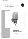
Electric Actuators
Linear Actuator
Type SAM -01 to SAM -52
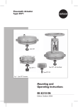
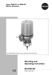
Fig. 1 ⋅ Type SAM -20 Linear Actuator, rated travel 30 mm, nominal thrust 6 kN
Mounting and
Operating Instructions
EB 8330 EN
Edition April 1999
Contents
Safety instructions . . . . . . . . . . . . . . . . . . . . . . . . . . . . . . . . . . . . . . . . . . . . . . . 3
1
Principle of operation . . . . . . . . . . . . . . . . . . . . . . . . . . . . . . . . . . . . . . . . . . . . . 4
1.1
1.2
1.3
1.3.1
Application
Versions
Function
Electrical equipment
2
Technical data . . . . . . . . . . . . . . . . . . . . . . . . . . . . . . . . . . . . . . . . . . . . . . . . . . 8
3
Dimensions . . . . . . . . . . . . . . . . . . . . . . . . . . . . . . . . . . . . . . . . . . . . . . . . . . . 11
4
Installation . . . . . . . . . . . . . . . . . . . . . . . . . . . . . . . . . . . . . . . . . . . . . . . . . . . 12
4.1
4.2
4.3
4.4
Installation requirements
Mounting position
Attaching the actuator to a control valve
Manual operation
5
5
5
6
12
12
12
14
5
Electrical connection . . . . . . . . . . . . . . . . . . . . . . . . . . . . . . . . . . . . . . . . . . . . . 15
5.1
5.2
5.3
Removing the cover
Establishing the connection
Start-up
6
Connection examples . . . . . . . . . . . . . . . . . . . . . . . . . . . . . . . . . . . . . . . . . . . . 19
Connection example 1(three-way valve)
Connection example 2 (globe valve)
16
17
17
19
20
7
Adjustment and calibration. . . . . . . . . . . . . . . . . . . . . . . . . . . . . . . . . . . . . . . . 21
7.1
7.2
7.3
7.4
7.5
Travel
Potentiometer
Electronic position transmitter
Limit switch WE-S3
Signal switch WE-S4 to WE-S6
21
21
22
24
24
8
Additional electrical equipment . . . . . . . . . . . . . . . . . . . . . . . . . . . . . . . . . . . . . 26
8.1
8.1.1
Heating
Retrofitting the heating resistor
9
Positioners. . . . . . . . . . . . . . . . . . . . . . . . . . . . . . . . . . . . . . . . . . . . . . . . . . . . 27
9.1
9.1.1
9.1.2
9.2
9.3
9.4
Electrical connection
Connecting the control line
Feedback signal
Corrections with potentiometer "A" and "B"
Reversing
Sequential mode
10
Maintenance and service . . . . . . . . . . . . . . . . . . . . . . . . . . . . . . . . . . . . . . . . . 29
10.1
Circuit diagram Type SAM - ... with positioner (maximum equipment)
26
26
27
28
28
28
29
29
30
•
Safety instructions
The actuators described below are part of a power plant installation for industrial applications.
They are designed in accordance with the generally applicable technical regulations.
The connection and start-up of the linear actuators requires expert knowledge on the installation
of power systems and equipment (according to DIN VDE 0100), on accident prevention regulations and the special start-up conditions for linear actuators.
These measures require qualified personnel.
According to these Mounting and Operating Instructions, qualified personnel is referred to as
individuals who are able to judge the work they are assigned to and recognize possible dangers
due to their specialized training, their knowledge and experience as well as their knowledge of
the applicable standards, e. g.
– training/instruction or authorization to activate/deactivate, isolate, ground, and mark devices/systems according to the safety engineering standards,
– training or instruction in accordance with the safety engineering standards regarding maintenance and application of suitable safety equipment,
– first aid training.
Symbols in these Mounting and Operating Instructions
Please observe the following special symbols
used in these Mounting and Operating Instructions.
!
NOTE!
Here, you will find supplementary details, information and tips.
Certain safety related information or instructions are brought to your attention.
!
CAUTION!
Indicates a potentially hazardous situation which, if not avoided, may
cause property damage!
WARNING!
Indicates a potentially hazardous situation which, if not avoided, could result in property damage or even personal injury !
Electrical or live parts are unprotected and
freely accessible. Risk of death!
!
DANGER!
Electrical power or live parts are
freely accessible.
If instructions as per these Mounting
and Operating Instructions are not
followed, death or serious injury and
property damage may result!
!
DANGER!
During installation and operation, suitable power supply systems must be used
to ensure that hazardous voltages are prevented from energizing the device in
standard operating mode or in case of a faulty system or system parts.
Otherwise, personal injury and/or property damage may result.
Any hazards which could be caused by the process medium, the signal pressure
and moving parts of the control valve are to be prevented by means of appropriate measure.
The proper and safe operation of this device depends on the proper shipping
and appropriate storage including attachments and installation as well as careful operation and maintenance.
You are required to ensure the following:
– Only qualified individuals must be assigned to work on this device.
– These individuals are required to read and have understood the Mounting and
Operating Instructions supplied with this product as well as the product information.
– These Mounting and Operating Instructions must always be available. Make
sure that the respective individuals strictly observe the instructions listed for
any work to be performed.
– Where applicable, tools and measuring instruments must be used properly
and in accordance with their intended purpose. If required, use your own protective gear.
– Work on this device or near this device must not be performed by unqualified
personnel.
1.
Principle of operation
The Type SAM ... Electric Linear Actuators are
equipped with reversible a.c. or three-phase
a.c. motors. The rotary motion of the motor is
transferred to the actuator stem via a gear unit
and the corresponding transfer elements
where it is converted into a linear "On-Off"
motion.
In case the electrical power fails, you can
operate the actuator manually.
Special features
– Nominal thrust from 2 to 25 kN
– Rated travel 15, 30, 60 or 120 mm
– Speed of response 13.5 to 50 mm/min
– A.c. motor 230 V~, 50 Hz
or
three-phase a.c. motor 400 V~, 50 Hz
– Degree of protection IP 65
1.1
Application
The linear actuators operate the final control
elements which require a linear travel motion
from 15 to 120 mm and a positioning force in
the range of 2 to 25 kN.
The shut-off force of the actuators is adjusted
permanently. The travel, however, can be
modified at a later date.
1.2
– One heating resistor to prevent the formation of condensation water underneath the
cover when the humidity is high and the ambient temperatures fluctuate considerably.
At an inside temperature of >60 °C, the
heating resistor deactivates the heating via
a temperature relay; it reactivates the heating at a temperature of <40 °C.
– One electronic positioner for the analog
control 0 (2) to 10 V / 0 (4) to 20 mA (only
for 230 V, 50 Hz AC motors).
Versions
The electrical components are located separately from the gear underneath the sealed
cover where they are protected from dust and
can be easily accessed when the cover is
removed.
The basic version of the device comprises:
– Two torque switches DE-S1 and DE-S2.
They switch off the motor when the force adjusted in the actuator is counterbalanced by
a corresponding force. Thus, they protect
the final control element from damage, and
the actuator from overload.
– One travel switch WE-S3 for limitation of
the travel in the opening direction.
– Two travel switches WE-S4 and WE-S5 for
indicating intermediate and positions of the
final control element.
1.3
Function
The rotary motion of the motor is transferred
to the gear wheel with a female thread via the
gearing.
The piston rod with the matching male thread
engages the female thread. An anti-rotation
device secures the rod and prevents it from rotating.
The piston rod performs a linear motion,
either pulling or pushing, when the female
threaded gear wheel is turned via the motor
gear.
The following components can be installed
optionally:
– A fourth travel switch WE-S6 for indicating
certain control element positions.
– One or two potentiometers or one electronic
position transmitter ESR for analog remote
transmission of the final control element’s
position.
"#
1.3.1 Electrical equipment
The electrical equipment is located underneath the removable housing cover.
In addition to the torque switches DE-S1 and
DE-S2 as well as three travel switches WE-S3,
S4 and S5, the actuator can be equipped with
the following switching elements and measuring instruments:
– One travel switch WE-S6
– Two potentiometers POT R1 and POT R2
– One electronic position transmitter ESR
– One positioner
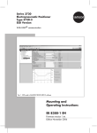
The axial movement of the actuator stem is
transferred via adjusting lever and slider to
the driving lever. The driving lever then produces a proportional rotary motion via gear
wheel as a measure for the two R1 and R2
potentiometers or the ESR positioner. The cam
discs located on the axis of the gear wheel
operate the switches WE-S3, WE-S4, WE-S5
and WE-S6 .
Fig. 2 ⋅ Function of switches and potentiometers,
travel transmission
!
- DE-S1, DE-S2, WE-S3
DE-S1 switches off the motor depending on
the torque when the actuator stem extends
(final control element "CLOSED") .
DE-S2 switches off the motor depending on
the torque when the actuator stem retracts
(final control element "OPEN"), provided that
the final control element can be subjected to
load in "ON" position.
NOTE!
The switching points of DE-S1 and DE-S2 are
factory default and cannot be modified.
WE-S3 switches off the motor depending on
the travel when the actuator stem retracts
(final control element "ON"), provided that
the actuator stem has completed its travel as
indicated in the ordering text.
- WE-S4, WE-S5, WE-S6
The travel switches WE-S4, WE-S5 and sometimes WE-S6 are not adjusted. If required,
they can be adjusted/retrofitted as limit or
signal switch (see section "7 Adjustment and
calibration").
- POT R1, POT R2, ESR
The actuators can be equipped with two
potentiometers POT R1 and POT R2
or
- with the Types SAM -20 to SAM -52 - with a
position transmitter ESR that has an output
signal of 4 (0) to 20 mA.
Both versions enable the analog remote transmission of the valve travel.
The potentiometers and the electronic position
transmitter are adjusted to the required travel.
They can be readjusted (see section "7 Adjustment and calibration").
"#
- Positioner
In combination with three-phase synchronous
a.c. or brake motors for 230 V, 50 Hz, a positioner may already be installed as factory
default (see section "9 Positioner").
Input signals:
− 4 (0) to 20 mA
or
− 0 to 10 V
When the actual value deviates from the set
point, a manipulated variable is generated to
control the actuator.
Fig. 4 ⋅ Positioner
Fig. 3 ⋅ Switches and potentiometers
$
%&
2
Technical data
Table 1 ⋅ Mechanical data
Type
SAM ...
Nominal thrust
kN
Rated travel
mm
Speed of
response
mm/min
Transit time at rated travel
Adjusted travel
s
-01
-10
-11
-12
-13
-20
-21
-22
-23
2
2
3.5
4.5
6
6
8
12
15
30
15
17 ⋅ 25 ⋅ 50
17
34
13.5 ⋅ 25 ⋅ 50
13.5
22 ⋅ 40
120
106 ⋅ 72 ⋅ 36
106
53
133 ⋅ 72 ⋅ 36
133
82 ⋅ 45
67 ⋅ 36 ⋅ 18
67 ⋅ 40
22.5
mm
Transit time
s
15
53 ⋅ 36 ⋅ 18
60
Mounting position
Actuator stem
53
26
Arbitrary, however, motor not vertically suspended.
No mechanical limit stops, anti-rotation device: tongue and groove
Handwheel
Side-mounted handwheel
Connecting thread
M 30 x 1.5
Degree of protection
IP 65 according to DIN 40050
−20 to +60 oC
Perm. ambient temperature
Table 2 ⋅ Electrical data
Electrical connection
Connected load
Inside terminal strip or terminal strip in terminal box, attached to
actuator or as compact switch
Single-phase a.c. 230 V, 50 Hz ⋅ Three-phase a.c. 400 V, 50 Hz
Operating mode acc. to VDE 0530
Part 1, section 4
Duty cycling S4 -30 % ED-600 c/h
Power consumption
Type SAM ... Actuator
Speed of response [mm/min.]
Nominal Motor 230 V~/50 Hz
current [A] Motor 400 V~/50 Hz
Motor type
Temperature monitor
-01
-10
-11
-12
-13
-20
-30
-21
-31
15
17 ⋅ 25
50
17 ⋅ 34
13.5 ⋅ 25
0.029
0.16
0.18
0.16 ⋅ 0.18
0.1 ⋅ 0.225
0.015
0.11
0.08
0.11 ⋅ 0.08
0.062 ⋅ 0.11
Synchronous motor
Not required, only on request
%&
Mechanical data
-30
-31
-32
-33
-40
-41
-42
-50
-51
-52
6
8
12
15
15
20
25
15
20
25
60
13.5 ⋅ 25
50
120
13.5
22 ⋅ 40
266 ⋅ 144
72
25 ⋅ 50
25 ⋅ 50
144 ⋅ 72
288 ⋅ 144
30
60
133 ⋅ 72
36
72 ⋅ 36
144 ⋅ 92
Arbitrary, however, motor not vertically suspended
No mechanical limit stops, anti-rotation device:
tongue and groove
Side-mounted handwheel
M 60 x 1.5
M 100 x 1.5
IP 65 according to DIN 40050
−20 to +60 oC
Electrical data
Inside terminal strip or terminal strip in terminal box, attached to
actuator or as compact switch
Single-phase a.c. 230 V, 50 Hz ⋅ Three-phase a.c. 400 V, 50 Hz
Duty cycling S4 -30 % ED-600 c/h
-22
-32
1)
-23
-33
-23
-33
-20
-30
-21
-31
-22
-32
-23
-33
-40
-50
-41
-51
-42
-52
13.5
22
50
40
25 ⋅ 50
0.145
0.225
0.7
0.7
0.66 ⋅ 0.93
0.85
0.11
0.29
0.29
0.4 ⋅ 0.7
Synchronous motor
Asynchronous motor 1)
Not required, only on request
Bimetallic-element switch
Actuators attached to a positioner require a brake motor
'
%&
Table 2 ⋅ Electrical equipment
Switching and signalling equipment
Torque switches DE- ...
Switch DE-S ...
Two switches S1 and S2 ⋅ Max. 250 V AC
Travel switches WE-...
Switch WE-S ...
Load
One switch S3 in opening or closing direction
Two switches S4 and S5 to signal intermediate or final positions
Switch S6 as signal switch (optional) 1)
cos ϕ = 1: max. 5 A ⋅ cos ϕ = 0.8: max. 3 A ⋅ Lightbulbs: max. 2 A
Potentiometer R
Potentiometer R ...
Load
One or two potentiometers R1 and R2 : 110 Ω, 200 Ω, 1 kΩ
Max. 1.5 W ⋅ Slider current max. 30 mA
Electronic position transmitter ESR 2)
Connection
Four-wire/three-wire connection
Two-wire connection
18 to 30 V DC
18 to 30 V DC
Max. load RL
50 ⋅ (UH − 2.5) Ω
50 ⋅ (UH − 12) Ω
Output signal
0 to 20 mA or 4 to 20 mA
Supply voltage UH
Current consumption
4 to 20 mA
Max. 30 mA
Electronic positioner 3)
Input and output signals
Heating resistor
1)
2)
3)
4 (0) to 20 mA or 0 to 10 V
With temperature monitor ⋅ 24/110/230 V DC/AC ⋅ 15 W
Only for Type SAM-20 to -50: Provided S6 is connected, only one potentiometer (R1) can be
connected in plug-type connections.
Only for Type SAM-20 to -52, optionally with potentiometer R1/R2 or position transmitter ESR
Only for brake motors or synchronous motors for 230 V, 50 Hz; for three-phase a.c. motors, external
reversing contactors are required.
3
(#
Dimensions
Table 3 ⋅ Dimensions in mm and weights
Type
Rated travel
SAM -01 . . . -13 SAM -20 ... -23 SAM -30 ... -33 SAM -40 ... -42 SAM -50 ... -52
mm
30
30
262 (277) 1)
H
60
60
300 (323) 1)
120
377 (417) 1)
H1
34
34
54
54
92
H2 max.
90
90
165
165
315
H3
160 (175) 1)
∅D
145
∅ D1
16
16
22
40
40
M 30 x 1.5
M 30 x 1.5
M 60 x 1.5
M 60 x 1.5
M 100 x 2
15
19
∅ D2
Thread
∅P
t
Weight approx. in kg
1)
175 (198) 1)
187 (227) 1)
184
216
74
130
~ 40
~ 60
5
6
7
Values in parentheses for linear actuators attached to positioners
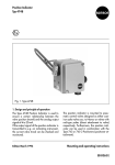
min. H31)
ØD
t
~15
Dimensional drawing
H3
H1
ØD2 H2
ØD1
ØP
1)
Rated travel
H
Minimum clearance to ensure that the cover can still be
removed after the actuator has been installed.
Fig. 5 ⋅ Dimensions of linear actuators Type SAM-01 to SAM-52
)
4
4.1
Installation
Installation requirements
Prior to installation, make sure that the following requirements are met:
– Proper voltages and control signals required to operate the actuator are available.
– Electrical lines are de-energized.
– Pipelines are depressurized and cold.
Choose the attachment position of the linear
actuator so as to ensure the following:
– The actuator can be easily accessed.
– There is sufficient space to remove the cover
(see "3 Dimensions").
– The actuator is protected against excessive
heat radiation.
– The ambient temperature is in the range
from -20 to +60 °C.
If installed outdoors, the actuator must be protected with an additional cover, e.g. against
humidity (rain, snow), heat (direct sunlight),
cold (frost), excessive draft, dust, etc.
When ambient temperatures are subjected to
strong fluctuations and if the humidity is high,
we recommend installing a heating resistor to
minimize the formation of condensate in the
housing (see "8.1 Heating").
If installed in an environment with a high pollutant concentration, (e.g. in areas with a high
traffic volume, industrial areas, near coastal
regions), the external actuator parts must be
made of non-corrosive material and be
coated with a special finish.
4.2
Mounting position
The mounting position is arbitrary, however,
the linear actuator must not be vertically suspended.
When mounted with the actuator stem in horizontal position, the yoke must be mounted
such that its two rods are positioned vertically
one on top of the other.
A
A–A
Yes!
No!
A
Fig. 6 ⋅ Mounting position with horizontal actuator stem
4.3
Attaching the actuator to a
control valve
On delivery, the actuator stem is extended to
the lower final position.
Prior to assembly, check the following:
– Does the technical data of the linear actuator match the application requirements?
– Is the valve complete (yoke on the actuator
or on the valve)?
– Are the coupling parts aligned?
– Is the linear actuator ready - with ring nut
and coupling parts for attachment to the
valve?
)
– If required, are additional accessories already installed in the actuator?
– Does the operating voltage to be connected
match that of the actuator?
– Does the data on the name plate match the
motor data?
– Does the adjusted travel of the actuator or
the travel to be adjusted also match the
valve travel?
8
7
1
9
2
3
4
6
5
1
2
3
4
5
Actuator stem
Coupling
Coupling nut
Lock nut
Plug stem
6
7
8
9
Travel indicator scale
Ring nut
Actuator
Yoke
Procedure
– Insert plug stem (5) into the valve as far as it
will go.
– Move actuator stem (1) to mid-position (see
"4.4 Manual operation").
– Place actuator (8) on the valve bonnet and
secure with ring nut (7) (allow to fall over the
stem when placing).
– Push plug stem (5) up, connect coupling nut
(3) and actuator stem (1) via the coupling
halves (2) and tighten with screws.
– Move actuator stem (1) to the final position
by turning the handwheel clockwise.
– Align travel indicator scale (6) with the tip of
the coupling (2) and screw tight.
– Tighten the plug stem (5) with the lock nut
(4) against the coupling nut (3).
!
CAUTION!
Do not press valve plug or final control
element onto the seat and turn.
This could cause the final control element and the actuator to be damaged.
The linear actuator can be attached similarly
to other final control elements, e. g. butterfly
valves with attached pedestal.
Fig. 7 ⋅ Assembly (detail)
)
4.4
Manual operation
In case the energy supply fails, or when installing and adjusting the actuator, the actuator stem can be "retracted or extended" manually
!
Actuator stem
retracts
CAUTION!
Do not operate the handwheel when
the motor is in motion.
Do not override the adjusted travel
range with the handwheel. Observe
the rated travel, otherwise the actuator could be damaged. This applies
especially to an uninstalled actuator.
Use the disengaging stem to unlock the motor
and actuator stem and move the stem using
the side-mounted handwheel.
– If the actuator is installed vertically, push
down the disengaging stem in the direction
of the extending actuator stem.
– Turn the handwheel alternately counterclockwise/clockwise, until it engages noticeably.
– If the direction of rotation is clockwise, the
actuator stem extends.
If the direction of rotation is counterclockwise, the actuator stem retracts.
The linear actuator then switches automatically back to motor operation as soon as you
release the disengaging stem.
Fig. 8 ⋅ Manual operation
Actuator stem
extends
5
Electrical connection
!
DANGER!
The connection and start-up of the linear actuators requires expert knowledge
on the installation of power systems and equipment (according to DIN VDE
0100), on accident prevention regulations and the special start-up conditions for
linear actuators.
This type of work must be performed by qualified personnel only (see p. 3
"Safety instructions").
– Be sure to disconnect the voltage prior to connecting the actuator to the power
supply. Ensure that the voltage cannot be switched on again accidentally!
– When installing the local lines and establishing the connection, you are required to observe the DIN-/VDE regulations as well as the regulations of your
local energy supplier.
– Be sure to check that the mains supply voltage and the system frequency
match the data on the name plate of the linear actuator as well as the actuator’s name plate.
– The cross section of line must be sized in accordance with the respective
power consumption of the linear actuator and the required line length.
Minimum cross section of lines: 1.5 mm2 or according to the local regulations.
Cross sections of lines that are not large enough are often the cause of supposed "malfunctions".
– Fuse of the system: max. 6 A
– Upstream controllers or switching devices must be sized sufficiently. If required, install a coupling relay between them.
– Isolation of the system’s power supply; to isolate and disconnect the power
supply line from the actuator for maintenance and calibration purposes, the
proper stop controls must be used which guarantee an all-pole disconnection
(except earth) when switched off. These stop controls must be lockable when
switched off and guarded against being switched on unintentionally.
– Use appropriate power supply systems which ensure that no hazardous voltages may reach the device in standard operation or in case of fault.
If you do not observe these safety regulations, death, severe physical injury or
considerable property damage may occur.
5.1
!
Removing the cover
WARNING!
Before you remove the cover and
when you perform any maintenance
or calibration work, you must first disconnect the power supply.
Protect the actuator against being
switched on again unintentionally!
– Unscrew cap nut.
– Remove seal ring.
– Hold the cover and slightly turn while removing.
Fig. 9 ⋅ Type SAM-20 Actuator, cover removed
!
DANGER!
Linear actuators with the cover removed may only be operated for short periods, e.g. for
test runs or essential calibration work on electric components such as potentiometers,
limit switches or position electronics. During these activities, hazardous energized, uninsulated, moving and rotating parts are easily accessible. If the calibration is performed
improperly or without the required caution, death, severe physical injury or property
damage may result.
This type of work may only be carried out by qualified personnel (see p. 3 "Safety instructions").
The operation of the actuator with the cover removed for a purpose other than the one
described above, is prohibited.
!
5.2
Establishing the connection
!
NOTE!
For the electrical connection, refer to the circuit
diagram displayed inside the lid!
If you adjust the travel to a value exceeding the given values, the actuator
may be damaged!
When installing electric lines, you are required to
observe the regulations governing power plant
installations!
Especially with 24-V-actuators, you should make
sure that the line cross sections are sufficiently
sized and that there is enough reserve capacity
left in the transformer.
– Route and secure the lines in the actuator
such that they are protected from moving or
rotating parts and cannot be damaged
when removing or replacing the cover.
WARNING!
The actuators must only be adjusted
electrically or manually within the
given travel.
A.C. motors
L ^= clamp 3
N ^= clamp 1
The actuator stem extends from the actuator
and moves to "CLOSED" position (closes).
N =^ clamp 1
L =^ clamp 2
The actuator stem retracts into the actuator
and moves to "OPEN" position (opens).
Three-phase a.c. drive motors
External reversing contactors should be used.
L1 ^= clamp 1; L2 ^= clamp 2; L3 ^= clamp 3
!
Fig. 10 ⋅ Terminal blocks for electrical connection
5.4
Start-up
The following applies for a first working simulation:
– Use handwheel to move actuator stem towards the center of the travel.
– Connect grounding contactor to grounding
contactor clamp .
– Connect supply voltage.
WARNING!
With the wrong direction of rotation,
even correctly wired torque switches
cannot switch off the motor. When
"testing" the operating direction, use
short-term commands only.
Switch on the supply voltage, thus issuing the
short-term command "OPEN/CLOSED" .
– Check, whether the actuator stem moves in
the right direction.
– If the actuator stem does not move in the
right direction, switch motor connections 2
and 3, and repeat test.
$
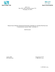
Connection diagram Types SAM-01 to -52
Switches and potentiometers
If a fourth WE S6 is installed:
Only 1 potentiometer POT R1 is possible for plugtype connection!
The travel switch S3 must be adjusted so that it limits the
travel of the final control element in the operating direction by switching off the motor (see section "7.4 Limit
switch WE-S3").
Do not exceed the travel adjusted at the linear actuator!
ESR
+ _
E
3~
HZ
DE
S1
DE
S2
WE
S3
WE
S4
WE
S5
WE
S6
25 26
1 2 3
+ _ S
E
A
25 26 27 28
Pot
R1
1~
Pot
R2
C
7 8
1 2 3
10 11 12 13 14 15 16 17 18 19 20 21 22 23 24 25 26 27
With brake
Without temperature
monitor TW
+ _
2)
TW
1~
TW
TW
1~
C
1 2 3
1 2 3
TW
TW
3~
HZ
Heating resistor
DE-S ... Torque limit switches
3~
4 5
1 2 3
4 5
1 2 3
4 5
1 2 3
~ ~
3~
4 5
1 2 3
with brake
WE-S ...Travel limit switches
ESR
Electronic position transmitter
25 (3.3 kΩ) is connected upstream at a speed of response of 50 mm/min.
Fig. 11 ⋅ Connection diagram of the Type SAM-01 to Type SAM-52 Linear Actuators
TW
C
Motor with temperature monitor TW
with brake
without brake
without brake
2) Resistor Type SRH
+ _
~ ~
1~
C
4 5
28 29 30 31 32 33
4 5
6
*#
Connection examples
Connection example 1 (three-way valve)
• Operation with single-phase alternating current (three-step control)
• Final switch-off via switch DE-S1 (limitation in closing direction "CLOSED") and DE-S2 (limitation in opening direction "OPEN"), load-dependent
NOTE!
If you want to operate the actuator with only two torque switches DE-S1 and DE-S2, the associated valve must be designed to accept the forces of the actuator.
Refer to the documentation for the valve. If required, contact your manufacturer!
Connecting the actuator
– Connect the grounding conductor of the
connecting line (green/yellow wire) to the
grounding conductor clamp
.
– N of connecting line to clamp 1.
– Control line extending actuator stem
"CLOSED" to clamp 11.
– Control line retracting actuator stem
"OPEN" to clamp 14.
– Insert jumpers; from clamp 10 to clamp 3
and from clamp 13 to clamp 2.
HZ
DE
S1
DE
S2
WE
S3
1~
C
1 2 3
N
Testing the actuator
– Use a three-step controller to control the actuator.
– Use an isolated screw driver to operate the
switching rolls of the switch and check
whether the switch actually does deactivate
the motor:
With extending actuator stem ->
upper switch DE-S1,
With retracting actuator stem ->
lower switch DE-S2,
– If required, switch the motor supply jumpers
on the clamps 2 and 3.
HZ
Heating resistor
DE-S1 Torque limit switch
S1, position "CLOSED"
DE-S2 Torque limit switch
S2, position "OPEN"
WE-S3 Travel limit switch S3,
position "OPEN"
R
7 8
10 11 12 13 14 15 16 17 18
Signal
"CLOSED"
"OPEN"
Fig. 12 ⋅ Circuit diagram, connection example 1
'
*#
Connection example 2 (globe valve)
• Operation with single-phase alternating current (three-step control)
• Final switch-off, actuator stem extending from the actuator (direction "CLOSED"), load-dependent via switch DE-S1
• Final switch-off, actuator stem retracting in the actuator (direction "OPEN"), load-dependent
via switch DE-S2 connected in series with switch WE-S3
Connecting the actuator
– Connect the grounding conductor of the
connecting line (green/yellow wire) to the
grounding conductor clamp
.
– N of connecting line to clamp 1.
– Control line extending actuator stem
"CLOSED" to clamp 11.
– Control line retracting actuator stem
"OPEN" to clamp 14.
– Insert jumpers; from clamp 10 to clamp 3,
from clamp16 to clamp 2, and from clamp
13 to clamp 17.
HZ
DE
S1
DE
S2
WE
S3
1~
C
1 2 3
N
R
7 8
10 11 12 13 14 15 16 17 18
Signal
"CLOSED" "OPEN"
Fig. 13 ⋅ Circuit diagram, connection example 2
Testing the actuator
– Use a three-step controller to control the actuator.
– Use an isolated screw driver to operate the
switching rolls of the switch and check
whether the switch actually does deactivate
the motor:
With extending actuator stem ->
upper switch DE-S1,
With retracting actuator stem ->
lower switch DE-S2 and
switch WE-S3.
– If required, switch the motor supply jumpers
on the clamps 2 and 3.
HZ
Heating resistor
DE-S1 Torque limit switch
S1, position "CLOSED"
DE-S2 Torque limit switch
S2, position "OPEN"
WE-S3 Travel limit switch S3,
position "OPEN"
7
7.1
&+#&,
Adjustment and calibration
Travel
On delivery, the linear actuator is adjusted
and calibrated to the travel indicated in the
ordering text. If required, you can change or
readjust the factory adjusted travel.
The slotted lever connected to the actuator
stem is equipped with travel "markers". The
scale inside indicates the adjustable travel
values.
To adjust the travel, the actuator stem must be
extended all the way to final position so that
the two adjustment levers are in parallel (final
control element "CLOSED"/travel indicator at
the bottom mark).
Procedure
– Use a wrench to loosen flat nut from the
slider.
– Move slider between the two slotted levers,
thus setting the desired travel according to
the marks.
– Secure slider with the flat nut again.
– Move position marks on the yoke to the new
final positions.
Fig. 14 ⋅ Travel adjustment
7.2
Adjusting the potentiometer
Depending on the version, the actuator can
be equipped with one or two potentiometers
(POT R1 and POT R2), see Fig.15.
When the actuator stem is in "OPEN"/
"CLOSED" position, the potentiometers POT
R1 and POT R2 must each be in final position.
NOTE!
The travel is infinitely variable, however, in
accordance with the data indicated on the
name plate, i.e. positions between the marks
can also be set.
After changing the travel, the limit switch WES3 must also be readjusted (see "7.4 Limit
switch WE-S3").
Fig. 15 ⋅ Potentiometer R1/R2
&+#&,
You can readjust the two potentiometers:
– Use handwheel to move the linear actuator
to the final position "actuator stem extended" ("CLOSED") until DE-S1 switches.
Adjusting lever and driving lever must be in
parallel in their tilted position.
– Use an appropriate screwdriver to move the
slider of the potentiometers to final position.
For this, turn the potentiometer shaft
counterclockwise until the stop can be just
felt.
– Move actuator by the adjusted travel to the
final position "actuator stem retracted"
("OPEN"). The potentiometers are then rotated into the other final position.
– Use a measuring instrument (ohmmeter) to
monitor the potentiometer movement and
check whether the entire potentiometer
range is being covered.
NOTE!
If the potentiometers reach the end stop when
reaching final position, the sliding clutch between potentiometer and pinion reacts and
prevents damage. However, a distinct reproducibility of the measuring results is not given
anymore.
In this case, a correspondingly higher travel
must be adjusted via the slider and the adjusting lever (see section "7.1 Adjusting the
travel").
For actuators with installed electric positioner,
R1 is internally linked to the controller. Its resistance value is therefore not transmitted to
the outside for indication.
7.3
Electr. position transmitter
Type SAM-20 to -52 Linear Actuators can be
equipped with an electronic position transmitter ESR in place of the two R1/R2 potentiometers.
The transmitter’s output signal indicates via
output current in the range from 4 (0) to
20 mA the position of the final control element. Therefore, it is especially suited for
remote transmission of the position.
Operating mode
The position transmitter can be operated in
two modes.
Use the mode selector switch to select "Normal mode" or "Reverse mode" .
N
R
1
2
Controls
1 Operating mode
2 Span
Fig. 16 ⋅ Electronic position transmitter, adjusters
for operating mode and span
NOTE!
The adjuster for the operating mode must always be in the final position of "Normal/Reverse", otherwise lower and upper
range value cannot be adjusted.
&+#&,
Normal mode
Rising characteristic when rotating the drive
gear wheel clockwise.
Reverse mode
Rising characteristic when rotating the drive
gear wheel counterclockwise.
Falling characteristic when rotating the drive
gear wheel counterclockwise.
Falling characteristic when rotating the drive
gear wheel clockwise.
NOTE!
With reverse final control elements, the position of the extended actuator stem corresponds to the final position "OPEN".
Normal mode
N
mA
20
Adjusting the 0 or 4 mA output signal
Move actuator in the position in which the output current is to be 0 or 4 mA.
0/4
0˚
80˚
270˚ 340˚
Reverse mode
Turn black adjustment wheel against the white
drive gear wheel to adjust the output current
to
– 3.98 to 4.02 mA for two-wire connection
– 0.01 to 0.02 mA for three-wire connection
R
NOTE!
In three-wire connections, there is no polarity
reversal at zero crossing. The device indicates
0 mA over a range of 8 degrees. Therefore,
you should select a value as small as possible,
however, other than zero (e. g. +0.01 mA).
mA
20
0/4
0˚
80˚
340˚
Span adjustment upon delivery
Maximum span
Minimum span
Span infinitely adjustable in this range
Fig. 17 ⋅ Span, range of adjustment
Adjusting the 20 mA output signal
– Move the actuator to the position in which
the output current is to be 20 mA.
– Set the output current to 20 ± 0.02 mA
using the span adjuster (see Fig. 16).
– Check the output signal adjustment for 0/4
mA, repeat adjustment if required.
&+#&,
7.4
Limit switch WE-S 3
- Type SAM-20 to SAM-52 Linear Actuators "Readjust" the cam disc associated with WES3 so that the actuator switches off after
reaching the required travel.
– Actuator stem in "OPEN" position (final position).
– Loosen knurled nut slightly, so that the cam
disc can be moved.
7.5
Signal switches
WE-S4 to WE-S6
- Type SAM-20 to SAM-52 Linear Actuators You can freely adjust the travel switches WES4, WE-S5 and WE-S6 to indicate certain
control element positions.
NOTE!
When the knurled nut is loose, the cam discs
may come loose unintentionally, thus changing the respective switching position.
– Adjust cam disc for WE-S3 in opening direction such that the switch deactivates the
actuator (check with gauge).
– Retain the position of the cam disc; retighten
knurled nut manually.
– Check the switching position in a test run.
Fig. 19 ⋅ Switches WE-S4 and WE-S5;
Switch S6 not installed
– Activate the required position for each
switch.
– Loosen knurled nut.
– Adjust the associated cam disc of each
switch accordingly (check switching point
with gauge).
– Retain the position of the cam disc; retighten
knurled nut manually.
– Check switching positions in a test run.
Fig. 18 ⋅ Switch WE-S 3 in the background with
associated cam disc
- Type SAM-01 to SAM-11 Linear Actuators The travel limit switches WE-S3 and WE-S6
are mounted on the lateral mounting plate.
They are operated via the operating cams located at the top end of the actuator stem.
Depending on the movement of the actuator
stem "OPEN"/"CLOSED", the associated
limit switch deactivates the actuator travel.
You can adjust the switching position at random by moving the respective switch axially
over the oblong hole, retighten.
"OPEN"
S3
Actuator stem
&+#&,
WE-S3
– Move actuator stem to final position manually ("OPEN") - actuator stem retracted -.
First, the switch WE-S3 must be above from
the operating cam.
WE-S6
– Move actuator stem to final position manually ("CLOSED") - actuator stem retracted -.
First, the switch WE-S6 must be below the
operating cam.
For both cases ...
– Loosen the mounting screws of the respective switch from the back side so that the
switch may be operated.
– Push the switch up/down until the operating
cams switch off the actuator - depending on
the travel - (check with a gauge).
– Retighten mounting screws.
Check switching position in a test run.
S6
"CLOSED"
Fig. 20 ⋅ Operating cams WE-S3/WE-S6
&&
-"#
8
8.1
Additional electr. equipment
Heating
We recommend the installation of a heating
resistor to prevent condensate from forming
underneath the cover, for instance, in applications with strongly fluctuating ambient temperatures, high humidity and in outdoor applications.
The heating resistor "R" is controlled via a
thermostatic switch "TW" (bimetallic-element
switch). A continuous-operation voltage is required for operation (indicate when ordering).
The switch-off temperature is approximately
+60°C, the re-start temperature +40°C.
– Secure heating resistor to the position intended for this purpose (see Fig. 22) using
the two self-cutting screws supplied with the
resistor.
– Secure temperature monitor in the respective bore hole of the mounting bracket (nut
width across flats 7).
– Connect the flexible lead end of the temperature monitor and the heating resistor to
clamps 7 and 8.
– Route and mount lines in the actuator such
that they are protected from moving or rotating parts and are not damaged when the
cover is removed or replaced.
TW
R
7 8
Fig. 21 ⋅ Heating resistor R and thermostatic switch TW,
circuit diagram
For power supply, connect the heating resistor
with thermostatic switch to clamps 7 and 8.
8.1.1 Retrofitting the heating resistor
You can install and connect a heating resistor
at a later date.
– Remove cover
!
Fig. 22 ⋅ Heating resistor(bottom), thermostatic switch
in the background (top)
9
Positioner
In a.c. brake motors for 230 V, 50 Hz, positioners can be installed as three-step controllers.
NOTE!
Under "normal" conditions, positioners are
combined with a.c. brake motors.
Three-phase a.c. motors require external reversing-contactor switches that must be interlocked with the travel and torque switches.
With these motors, start-up must be carried
out with special care, because in the event of
an incorrect phase sequence and, hence, a
wrong direction of rotation, the limit switches
have no effect either. They would interrupt the
"wrong" contactor.
Property damage may occur if the above precautions are not observed.
The positioner is located on the printed circuit
board above the motor, final controlling element and terminal strip (see Fig. 23).
When the cover is removed, the components
for connection, adjustment and readjustment
can be easily accessed.
The positioner controls the actuator via a loadindependent d.c. current or voltage signal as
reference variable. The respective rated travel is
assigned to the reference variable.
The controlled variable (actual value) and the reference variable (set point) in the range of 0 to 10
V or 0 to 20 mA are compared with each other.
If the actual value deviates from the set point,
a manipulated variable is generated to control the actuator until set point and actual
value match.
For signal feedback (actual value), POT R1 (1
kΩ−Poti) of the actuator is used.
NOTE!
The actuator is adjusted as factory default to
the given control range and travel.
9.1
Electrical connection with
positioner
See also section "10.1 Circuit diagram Type
SAM ... with positioner".
!
Fig. 23 ⋅ Location of the positioner
DANGER!
Observe the safety regulations governing handling of electrical systems
as described in section "5 Electrical
connection"!
– Connect grounding conductor of the supply
line to the grounding conductor clamp
.
– Directly grounded conductor "N" of the
supply voltage to clamp 1.
– Permanent phase "L" (operating voltage) to
clamp 54 of the positioner’s circuit board.
$
9.1.1 Connecting the control line
For the connection of the lines, refer to section
"5.2 Establishing the connection ".
NOTE!
To keep the influence of the disturbing pulse
as small as possible, the control signal (set
point) must be routed to the actuator via separate line with tin-plated copper braiding as
screening!
Control voltage 0 (2) to 10 V:
(−) Clamp 57
(+) Clamp 56
Control current 0 (4) to 20 mA:
(−) Clamp 57
(+) Clamp 59
10 V (20 mA) ^= Actuator stem up ("OPEN")
2 V (4 mA) ^= Actuator stem down ("CLOSED")
9.1.2 Feedback signal
You can measure the actual value either as:
– Voltage 0 (2) to 10 V
(−) Clamp 58
(+) Clamp 61 or
– Current 0 (4) to 20 mA:
(−) Clamp 58
(+) Clamp 60
The output signal always corresponds to the
input signal at a tolerance of approx. 200 mV
or 0.2 mA compared to the input.
The feedback signal is in the same direction,
i.e. an increasing input signal (set point) also
causes an increasing feedback signal.
The feedback signal must not be adjusted and
is not electrically isolated from the input.
Fig. 24 ⋅ Potentiometer "A" and "B",
Poti "B" on left, Poti "A" on right;
reversing plug in background
9.2
Corrections with potentiometers "A" and "B"
An LED simplifies the adjustment of the final
points.
– Potentiometer "A" for upper set point mark:
Turn clockwise, travel becomes shorter.
– Potentiometer "B" for lower set point mark:
Turn clockwise, travel becomes longer.
The red LED signalizes: actuator in final position, no manipulated variable is generated,
the set point has been reached.
9.3
Reversing
By turning the reversing plug (see Fig. 24), the
direction of rotation is reversed by 180 degrees, i. e. the motor’s direction of travel is
reversed with regard to the set point.
– Disconnect actuator from the supply voltage.
– Remove reversing plug, turn by 180 degrees and plug back in.
– Reconnect actuator to supply voltage .
– If required, correct with Poti "A" or "B".
9.4
Sequential mode
You can also operate the positioner in sequential mode. The lowest range is 2 V or 4 mA.
The position of the sequence within the range
of 0 to 10 V or 4 to 20 mA is arbitrary. Use
the trimming potentiometers "A" and "B" to
adjust the respective final value.
&.
10
!
Maintenance and service
WARNING!
Before you remove the cover and
prior to any maintenance and adjustments, disconnect the supply voltage
to the actuator.
Ensure that the actuator cannot be
switched on again accidentally!
The gearing and the actuator stem must be relubricated after approx. 200,000 double
strokes. We recommend the following lubricants:
– Standard and tropics version:
Klüber Microlube GL 261
– Oxygen version:
BARRIERTA L55/3 OX.
Do not attempt to repair the linear actuator on
site. Defective actuators must be sent together
with a fault report including the product number to SAMSON AG.
The upper range value must be adjusted first.
Use the potentiometer "A" to adjust the upper
range sequential mark. Use the potentiometer
"B" to adjust the lower range sequential mark.
'
&.
10.1 Circuit diagram Type SAM -... with positioner (maximum equipment)
Two-wire connection
ESR
+ – –
25 26
Four-/three-wire
connection
+ –
–
25 26 27 28
HZ
DE
S1
DE
S2
WE
S3
WE
S4
WE
S5
WE
S6
Output
mA
24 V−
Supply
1~
POT
R1
C
POT
R2
R
1 2 3
4 5
7 8
10 11 12 13 14 15 16 17 18 19 20 21 22 23 24 25 26 27 28 29 30 31 32 33
Mp/N
yellow
gray
red
brown
violet
blue
- The circuit diagram shows the maximum equipment.
- Input 0 (4) to 20 mA or 0 (2) to 10 V is determined by the manufacturer as per order.
- Auxiliary power connection (230 V) to clamps 54 (L) and 55 (Mp/N).
- Electronic position transmitter ESR only for Type SAM-20 to Type SAM-52.
Fig. 25 ⋅ Circuit diagram, Type SAM-01 to SAM-52 Electric Linear Actuators with positioner
&.
Positioner (positioning electronics)
possible RC variants
on demand
RC
RC
Reversing by turning
the plug
RC
Potentiometer plug
RC
54 53 52 51
yellow
gray
red
brown
violet
blue
L1
55 56 57 58 59 60 61
+ – – +
Input
V mA
Output
mA
Output
V
DE
WE
POT
HZ
ESR
Torque switches
Travel switches
S3 for travel limitation
S4 to S6 for reporting intermediate positions
Potentiometer
Heating resistor with temperature monitor
Electronic position transmitter (Type SAM-20 to 52 only)
EB 8330 EN
S /CD 07.99
SAMSON AG ⋅ MESS- UND REGELTECHNIK
Weismüllerstraße 3 ⋅ D-60314 Frankfurt am Main
Telefon (0 69) 4 00 90 ⋅ Telefax (0 69) 4 00 95 07
Internet: http://www.samson.de