1
Electropneumatic Positioner
Type 3730-0
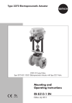
Fig. 1 · Type 3730-0
Mounting and
Operating Instructions
EB 8384-0 EN
Edition February 2005
Contents
Contents
Page
1
1.1
Design and principle of operation . . . . . . . . . . . . . . . . . . . 4
Technical data . . . . . . . . . . . . . . . . . . . . . . . . . . . . . 6
2
2.1
2.1.1
2.1.2
2.2
2.3
2.4
Attachment to the control valve – Mounting parts and accessories . . . . 7
Direct attachment . . . . . . . . . . . . . . . . . . . . . . . . . . . 10
Type 3277-5 Actuator. . . . . . . . . . . . . . . . . . . . . . . . . 10
Type 3277 Actuator . . . . . . . . . . . . . . . . . . . . . . . . . . 12
Attachment according to IEC 60534-6 . . . . . . . . . . . . . . . . . 14
Reversing amplifier for double-acting actuators . . . . . . . . . . . . . 16
Attachment to Type 3510 Micro-flow Valve. . . . . . . . . . . . . . . 18
3
3.1
3.1.1
3.1.2
3.2
Connections . . . . .
Pneumatic connections
Signal pressure gauges
Supply pressure . . . .
Electrical connections .
4
4.1
Operation . . . . . . . . . . . . . . . . . . . . . . . . . . . . . . 23
Operator controls . . . . . . . . . . . . . . . . . . . . . . . . . . . 23
5
5.1
5.2
5.3
5.4
5.5
5.6
5.7
5.8
5.9
5.10
5.11
5.12
5.13
Start-up and settings . . . . . .
Default switch positions . . . . .
Fail-safe position . . . . . . . .
Volume restriction Q . . . . . .
Presetting the travel . . . . . . .
Direction of action. . . . . . . .
Connecting the positioner . . . .
Limiting the output signal pressure
Presetting zero . . . . . . . . .
Gain factor . . . . . . . . . . .
Reference variable . . . . . . .
Adjusting zero . . . . . . . . .
Adapting the travel . . . . . . .
Activate the tight-closing function
6
Maintenance . . . . . . . . . . . . . . . . . . . . . . . . . . . . . 28
7
Servicing explosion-protected devices . . . . . . . . . . . . . . . . . 28
8
Dimensions in mm . . . . . . . . . . . . . . . . . . . . . . . . . . 29
2
EB 8384-0 EN
.
.
.
.
.
.
.
.
.
.
.
.
.
.
.
.
.
.
.
.
.
.
.
.
.
.
.
.
.
.
.
.
.
.
.
.
.
.
.
.
.
.
.
.
.
.
.
.
.
.
.
.
.
.
.
.
.
.
.
.
.
.
.
.
.
.
.
.
.
.
.
.
.
.
.
.
.
.
.
.
.
.
.
.
.
.
.
.
.
.
.
.
.
.
.
.
.
.
.
.
.
.
.
.
.
.
.
.
.
.
.
.
.
.
.
.
.
.
.
.
.
.
.
.
.
.
.
.
.
.
.
.
.
.
.
.
.
.
.
.
.
.
.
.
.
.
.
.
.
.
.
.
.
.
.
.
.
.
.
.
.
.
.
.
.
.
.
.
.
.
.
.
.
.
.
.
.
.
.
.
.
.
.
.
.
.
.
.
.
.
.
.
.
.
.
.
.
.
.
.
.
.
.
.
.
.
.
.
.
.
.
.
.
.
.
.
.
.
.
.
.
.
.
.
.
.
.
.
.
.
.
.
.
.
.
.
.
.
.
.
.
.
.
.
.
.
.
.
.
.
.
.
.
.
.
.
.
.
.
.
.
.
.
.
.
.
.
.
.
.
.
.
.
.
.
.
.
.
.
.
.
.
.
.
.
.
.
.
.
.
.
.
.
.
.
.
.
.
.
.
.
.
.
.
.
.
.
.
.
.
.
.
.
.
.
.
.
.
.
.
.
.
.
.
.
.
.
.
.
.
.
.
.
.
.
.
.
.
.
.
.
.
.
.
.
.
.
.
.
.
.
.
.
.
.
.
.
.
.
.
.
.
.
.
.
.
.
.
.
.
.
.
.
.
.
.
.
.
.
.
.
.
.
.
.
.
20
20
20
20
21
24
24
24
24
24
25
25
25
25
25
26
26
27
27
Safety instructions
General safety instructions
4 The positioner may only be assembled, started up or operated by trained
4
4
4
4
and experienced personnel familiar with the product.
According to these mounting and operating instructions, trained personnel is
referred to as individuals who are able to judge the work they are assigned
to and recognize possible dangers due to their specialized training, their
knowledge and experience as well as their knowledge of the relevant
standards.
Explosion-protected versions of this positioner may only be operated by
personnel who have undergone special training or instructions or who are
authorized to work on explosion-protected devices in hazardous areas.
Refer to section 7 on Servicing explosion-protected versions.
Any hazards that could be caused by the process medium, the operating
pressure, the signal pressure or by moving parts of the control valve are to
be prevented by means of the appropriate measures.
If inadmissible motions or forces are produced in the actuator as a result of
the supply pressure level, it must be restricted by means of a suitable supply
pressure reducing station.
Proper shipping and appropriate storage are assumed.
4 Note! The device with a CE marking fulfils the requirements of the Directives
94/9/EC (ATEX) and 89/336/EEC (EMC).
The declaration of conformity can be viewed and downloaded on the
Internet at http://www.samson.de.
Positioner versions
Explosion
protection
Type 3730 -0
Without
II 2 G EEx ia IIC T6 / II 2 D IP 65 T 80 °C acc. to ATEX
II 3 G EEx nA/nL IIC T6 / II 3 D IP 65 T 80 °C acc. to ATEX
X
0
1
8
EB 8384-0 EN
3
Design and principle of operation
1
Design and
operation
principle
of
The electropneumatic positioner is mounted
to pneumatic control valves and is used to
assign the valve position (controlled variable x) to the control signal (reference variable w). The DC control signal received from
a control unit is compared to the travel of
the control valve and issues a signal pressure (output variable y).
The output signal pressure supplied by the
booster can be limited over the DIP switch
S5.
The volume restriction Q (10) and the switch
S6 are used to optimize the positioner by
adapting it to the actuator size and changing the gain factor.
The positioner is designed depending on the
corresponding accessories for direct attachment to Type 3277 Actuators or for attachment to actuators according to IEC 60534-6
(NAMUR).
The positioner basically consists of a travel
sensor system which is proportional to resistance, an analog i/p converter with downstream air capacity booster, and an analog
controller electronics.
The position of the valve is transmitted as
linear travel motion via pick-up lever and
travel sensor (2) to an analog PD controller
(3). The PD controller compares this actual
position to the 4 to 20 mA DC control signal
received from a control unit. In case of a
system deviation, the operation of the i/p
converter (6) is changed so that the actuator
(1) is filled or vented via the downstream air
capacity booster (7). This causes the valve
plug to move to the position determined by
the reference variable.
The pneumatic air capacity booster (7) and
the pressure regulator (8) are provided with
supply air. An intermediate flow regulator
(9) with fixed settings is used to purge the
positioner and also guarantees trouble-free
operation of the pneumatic booster.
4
EB 8384-0 EN
Tight-closing function:
The pneumatic actuator is completely filled
with air or vented as soon as the reference
variable falls below or exceeds a preset
value.
Fail-safe action “Actuator stem extends”
(AIR TO OPEN):
Deactivation when switching point of
4.32 ± 0.16 mA is not reached:
The actuator is vented and a globe valve is
closed tightly by the force of the actuator
springs.
In the case of a three-way valve, port B is
closed in mixing valves and port A is closed
in diverting valves.
Design and principle of operation
Fail-safe action “Actuator stem retracts”
(AIR TO CLOSE)
Activation when switching point of
19.68 ± 0.16 mA is exceeded:
The actuator is filled with air and a globe
valve is closed tightly by the signal pressure.
In three-way valves, port B (mixing service)
is closed and port A (diverting service) is
closed.
1
2
3
4
6
7
8
9
10
Control valve
Travel sensor
PD controller
DIP switches
i/p converter
Air capacity booster
Pressure regulator
Flow regulator
Volume restriction
4
3
w
x
2
6
9
8
Q
7
10
y
1
x
Fig. 2 · Functional diagram
EB 8384-0 EN
5
Design and principle of operation
1.1
Technical data
Positioner
Nominal travel,
adjustable
Direct attachment to Type 3277: 5.3 to 30 mm,
Attachment acc. to IEC 60534-6: 5.3 to 200 mm
Travel range
Adjustable within the rated travel, max. ratio 1:5
Reference variable w
Signal range 4 to 20 mA, split-range range 4 to 12 mA/12 to 20 mA, selectable at
DIP switches. 2-wire device, reverse polarity protection, static destruction limit 100 mA.
Minimum current
> 3.6 mA
Load impedance
Version without explosion protection: ≤6 V (corresponding to 300 Ω at 20 mA),
explosion-protected version: ≤6 V
Supply air
Supply pressure from 1.4 to 6 bar (20 to 90 psi),
Air quality acc. to ISO 8573-1: Max. particle size and density: Class 4
Oil content: Class 3, pressure dew point: Class 3 or at least 10 K below the lowest ambient temperature to be expected
Signal pressure (output)
0 bar up to supply pressure, can be limited to approx. 2.4 bar over DIP switch
Characteristic
Linear;
Hysteresis
≤1 %
Sensitivity
≤0.1 %
Direction of action
Selectable over DIP switch
Air consumption, st. state
Independent of supply pressure approx. 120 ln/h
Air delivery
Actuator pressurized
Actuator vented
At ∆p =6 bar: ≥ 8.5 mn3/h, at ∆p = 1.4 bar: 3.0 mn3/h
at ∆p =6 bar: ≤14.0 mn3/h, at ∆p = 1.4 bar: 4.5 mn3/h
Deviation from terminal-based conformity ≤1 %
KVmax(20 °C) = 0.09
KVmax(20 °C) = 0.15
Permissible ambient
temperature
–20 to +80 °C, with metal cable gland –40 to +80 °C
The limits specified in the EC Type Examination Certificate additionally apply for
explosion-protected devices.
Influences
Temperature: ≤0.15 %/10 K
Supply air: None
Vibration: ≤0.25 % up to 2000 Hz and 4 g acc. to IEC 770
Electromagnetic
compatibility
Complying with requirements specified in EN 61000-6-2, EN 61000-6-3 and NAMUR
Recommendation NE 21
Explosion protection
II 2 G EEx ia IIC T6 / II 2 D IP 65 T 80 °C or
II 3 G EEx nA/nL IIC T6 / II 3 D IP 65 T 80 °C
Degree of protection
IP 65
Materials
Die-cast aluminum GD AlSi12 acc. to DIN 1725 ( 3.2582), chromated and plastic
coated; External parts: Stainless steel 1.4571 and 1.4301
Weight
Approx. 1 kg
6
EB 8384-0 EN
Attachment to the control valve – Mounting parts and accessories
2
The travel that can be implemented at the
valve is restricted by the pin position used
and additionally by the selected fail-safe action and the actuator spring compression required.
Attachment to the control
valve – Mounting parts and
accessories
The positioner can be attached either directly to a SAMSON Type 3277 Actuator or
according to IEC 60534-6 (NAMUR) to control valves with cast yokes or rod-type yoke.
The positioner is standard equipped with the
lever M (pin position 35).
For attachment to the various actuators, corresponding mounting parts and accessories
are required. These are listed with their order numbers in Tables 1 to 4.
Note!
If the standard mounted lever M (pin position 35) is replaced, the newly mounted lever must be moved once all the way as far
as it will go in both directions to adapt it to
the internal measuring lever.
On attaching the positioner, it is important
to observe the assignment between lever
and pin position according to the travels
listed in the travel tables.
Travel table for direct attachment to Type 3277 Actuator
Type
3277-5
and
3277
Actuators
Actuator size
cm2
Rated travel
mm
Adjustment range at positioner
Min.
Travel
Max.
Required
lever
Assigned
pin position
120
7.5
5.3
20
M
25
120/240/350
15
5.3
35.4
M
35
700
30
9.5
50
M
50
Required
lever
Assigned
pin position
Travel table for attachment according to IEC 60534-6 (NAMUR)
SAMSON valves
Type 3271
Actuator
Other valves/actuators
cm2
Rated travel mm
60 and 120 with
Type 3510 Valve
7.5
5.3
17.6
S
17
120
7.5
5.3
17.6
M
25
Min.
Travel
Max.
120/240/350
15
7.5
35.4
M
35
700/1400/2800
15 and 30/30
10
50
M
50
1400/2800
60
14
70.8
L
70
1400/2800
60
20
100
L
100
2800
120
40
200
XL
200
EB 8384-0 EN
7
Attachment to the control valve – Mounting parts and accessories
Table 1
Direct attachment to Type 3277-5 Actuator
Mounting parts For actuators with 120
Accessories
for the
actuator
cm2
Order no.
effective diaphragm area, see Fig. 3
1400-7452
Switchover plate (old) for Actuator Type 3277-5xxxxxx.00 (old)
1400-6819
Switchover plate new for Actuator Type3277-5xxxxxx.01 (new)
1400-6822
Connecting plate for additional attachment of a solenoid valve G 1/8
Connecting plate (old) for Actuator Type 3277-5xxxxxx.00 (old) 1/8 NPT
1400-6820
1400-6821
Connecting plate new for Actuator Type 3277-5xxxxxx.01 (new)
1400-6823
Note: Only new switchover and connecting plates can be used with new actuators (Index 01).
Old and new plates are not interchangeable.
Accessories
for the
positioner
Table 2
Connecting plate (6)
G ¼: 1400-7461
¼ NPT: 1400-7462
or pressure gauge bracket (7)
G ¼: 1400-7458
¼ NPT: 1400-7459
Pressure gauge mounting kit (8) (output and
supply)
Stainless steel/Brass:
1400-6950
Stainless steel/St. steel:
1400-6951
Direct attachment to Type 3277 Actuator
Mounting parts for actuators with 240, 350 and 700 cm2, see Fig. 4
Accessories
8
1400-7453
Required piping with screw fittings for "Actuator
stem retracts" or when the top diaphragm
chamber is filled with air
cm2
240
350
700
Connection block with seals and screw
G 1/4: 1400-8811
¼ NPT: 1400-8812
Pressure gauge mounting kit (output and supply)
Stainless steel/Brass:
1400-6950
Stainl. steel/St. steel:
1400-6951
EB 8384-0 EN
Steel
1400-6444
1400-6446
1400-6448
Stainl. steel
1400-6445
1400-6447
1400-6449
Attachment to the control valve – Mounting parts and accessories
Table 3
Attachment to NAMUR ribs or control valves with rod-type yokes (rod diameter Ø 35 mm or smaller)
according to IEC 60534-6, see Fig. 5
Travel in mm Lever
For actuators
7.5
S
Type 3271-5 Actuator with 60/120 cm2 on Type 3510
Valve, see Fig. 7
Order no.
1400-7457
5 to 50
Without (lever M on
basic model)
Actuators from other manufacturers and Type 3271 with 120
to 700 cm2
1400-7454
14 to 100
L
Actuators from other manufacturers and Type 3271 with
1400 cm2
1400-7455
40 to 200
XL
Actuators from other manufacturers and Type 3271 with
2800 cm2, 120 mm travel
1400-7456
30 or 60
L
Type 3271 Actuator with 2800 cm2 and 30 or 60 mm travel
1400-7466
Mounting brackets for Emerson and Masoneilan linear actuators
In addition, a mounting kit acc. to IEC 60534-6 is required depending on the travel. See row above.
Accessories
Table 4
Connecting plate
G ¼: 1400-7461
¼ NPT: 1400-7462
or pressure gauge bracket (7)
G ¼: 1400-7458
¼ NPT: 1400-7459
Pressure gauge mounting kit (output/supply)
St. steel/Brass: 1400-6950
1400-6951
St. steel/St. steel:
General accessories
Pneumatic reversing amplifier for double-acting
actuators
Cable gland M20 x 1.5
Accessories
1400-6771
G¼
¼ NPT
Nickel-plated brass
1890-4875
Adapter M 20 x 1.5 to ½ NPT, aluminum
Cover plate with list of parameters
and operating instructions
1079-1118
1079-1119
0310-2149
German/English (standard)
English/Spanish
English/French
1990-3528
1990-5769
1990-5768
EB 8384-0 EN
9
Attachment to the control valve – Mounting parts and accessories
2.1
Direct attachment
2.1.1 Type 3277-5 Actuator
Refer to Table 1 on page 8 for the required
mounting parts as well as the accessories
with their order numbers.
Note the travel table on page 7!
Actuator with 120 cm2
Depending on the type of positioner attachment, the signal pressure is routed either left
or right of the yoke through a bore to the
actuator diaphragm. Depending on the
fail-safe action of the actuator "Actuator
stem extends" or "Actuator stem retracts"
(valve closes or opens if the supply air fails),
the switchover plate (9) must first be attached to the actuator yoke. Align the
switchover plate with the corresponding
symbol for left or right attachment according
to the marking (view looking onto the
switchover plate).
1. Mount connecting plate (6) or pressure
gauge bracket (7) with pressure gauges
onto the positioner, making sure both
seal rings (6.1) are seated properly.
2. Remove vent plug (4) on the back of the
positioner and close the signal pressure
output "Output 38" on the connecting
plate (6) or on the pressure gauge
bracket (7) with the stopper (5) included
in the accessories.
3. Place follower clamp (3) on the actuator
stem, align and screw tight so that the
mounting screw is located in the groove
of the actuator stem.
10
EB 8384-0 EN
4. Mount cover plate (10) with narrow side
of the cut-out opening (Fig. 3, on the
left) pointing towards the signal pressure
connection. Make sure that the bonded
gasket (14) points towards the actuator
yoke.
5. 15 mm travel: Keep the follower pin (2)
at lever M (1) on the back of the
positioner in the pin position 35 (delivered state).
7.5 mm travel: Remove the follower pin
(2) from the pin position 35, reposition it
in the bore for pin position 25 and
screw tight.
6. Insert formed seal (15) in the groove of
the positioner casing.
7. Place positioner on the cover plate (10)
in such a manner that the follower pin
(2) rests on the top of the follower clamp
(3). Adjust the lever (1) correspondingly
and open the positioner cover to hold
the positioner shaft in position at the cap
or the switch. The lever (1) must rest on
the follower clamp with spring force.
Mount the positioner on the cover plate
(10) using the two fixing screws. During
the installation make sure that the seal
ring (10.1) is inserted in the bore of the
intermediate plate.
8. Mount cover (11) on the other side.
Make sure that the vent plug points
downwards when the control valve is installed to allow any condensed water
that collects to drain off.
Attachment to the control valve – Mounting parts and accessories
Symbols
Switchover plate (9)
Actuator stem
extends
Attachment left
Attachment
right
Actuator stem
retracts
Signal pressure
input for left
attachment
Marking
Signal pressure
input for right
attachment
15
14
1
1.1
1.2
Lever
Nut
Disk spring
2
3
Follower pin
Follower clamp
4
5
Vent plug
Stopper
6
Connecting plate
6.1
Seal rings
7
8
Pressure gauge bracket
Press. gauge mounting kit
9
Switchover plate f. actuator
10
10.1
11
14
15
Cover plate
Seal ring
Cover
Gasket
Formed seal
1
2
3
1.1
1.2
Cut-out of cover
plate
4
6.1
6
5
Supply 9
10.1
10
6
Important!
Output 38
7
8
9
11
Always use the connecting plate (6)
included in the accessories to connect
supply and output.
Never screw threaded parts directly
into the housing.
Fig. 3 · Direct attachment – Signal pressure connection for Type 3277-5 Actuator with 120 cm2
EB 8384-0 EN
11
Attachment to the control valve – Mounting parts and accessories
2.1.2 Type 3277 Actuator
Refer to Table 2 on page 8 for the required
mounting parts as well as the accessories
with their order numbers.
Note the travel table on page 7!
Actuators with 240 to 700 cm2
The positioner can be mounted either on the
left or on the right side of the yoke. The signal pressure is routed to the actuator over
the connection block (12), for actuators with
fail-safe action "Actuator stem extends" internally through a bore in the valve yoke
and for "Actuator stem retracts" through external piping.
1. Place follower clamp (3) on the actuator
stem, align and screw tight so that the
mounting screw is located in the groove
of the actuator stem.
2. Mount cover plate (10) with narrow side
of the cut-out opening (Fig. 4, on the
left) pointing towards the signal pressure
connection. Make sure that the bonded
gasket (14) points towards the actuator
yoke.
3. For actuators with 700 cm2, remove the
follower pin (2) at lever M (1) on the
back of the positioner from pin position
35, reposition it in the bore for pin position 50 and screw tight.
For actuators 240 and 350 cm2 with
15 mm travel, the follower pin (2) remains in pin position 35.
4. Insert formed seal (15) in the groove of
the positioner casing.
12
EB 8384-0 EN
5. Place positioner on the cover plate in
such a manner that the follower pin (2)
rests on the top of the follower clamp
(3). Adjust the lever (1) correspondingly
and open the positioner cover to hold
the positioner shaft in position at the cap
or the switch. The lever (1) must rest on
the follower clamp with spring force.
Mount the positioner on the cover plate
(10) using the two fixing screws.
6. Make sure that the tip of the gasket (16)
projecting from the side of the connection block (12) is positioned above the
actuator symbol that corresponds with
the actuator with fail-safe action "Actuator stem extends" or "Actuator stem retracts." If necessary, remove the three
fixing screws and the cover. Then reposition the gasket (16) turned by 180°.
The previous version of the connection
block (Fig. 4, bottom) requires the switch
plate (13) to be turned such that the corresponding actuator symbol points to the
marking.
7. Place the connection block (12) with the
associated seal rings against the
positioner and the actuator yoke. Screw
it tight using the fixing screw (12.1). For
actuators with fail-safe action "Actuator
stem retracts", additionally remove the
stopper (12.2) and fit on the external
signal pressure piping.
8. Mount cover (11) on the other side.
Make sure that the vent plug points
downwards when the control valve is installed to allow any condensed water
that collects to drain off.
Attachment to the control valve – Mounting parts and accessories
1
Lever
1.1 Nut
1.2 Disk spring
2 Follower pin
3 Follower clamp
10 Cover plate
11 Cover
12.1 Screw
12.2 Stopper or connection for
external piping
13
14
Switch plate
Gasket
15
Formed seal
16
Gasket
15
10 14
1 2
12 Connection block
11
3
2
Lever M
1.1
1.2
Cut-out of
cover plate (10)
16
A
16 12
Actuator stem
retracts
extends
13
12
SUPPLY
12.1 12.2
SUPPLY
Connection block (old)
with switch plate (13)
Actuator stem retracts
B
Actuator stem extends
12
Marking
12.1
12.2
Fig. 4 · Direct attachment – Signal pressure connection for Type 3277 Actuator with 240, 350 and 700 cm2
EB 8384-0 EN
13
Attachment to the control valve – Mounting parts and accessories
2.2
Attachment according to
IEC 60534-6
The positioner is attached to the control
valve with a NAMUR bracket (10).
Refer to Table 3 on page 9 for the required
mounting parts as well as the accessories
with their order numbers.
Note the travel table on page 7!
1. Screw the two bolts (14) to the bracket
(9.1) of the stem connector (9), place the
follower plate (3) on top and use the
screws (14.1) to tighten.
Actuator size 2800 cm2:
For a travel of 60 mm or smaller, screw the
longer follower plate (3.1) directly to the
stem connector (9). For a travel exceeding
60 mm, mount the bracket (16) first and
then the follower plate (3) to the bracket together with the bolts (14) and screws (14.1).
2. Mount NAMUR bracket (10) to the control valve as follows:
For attachment to the NAMUR rib, use
an M8 screw (11) and toothed lock
washer directly in the yoke bore.
For attachment to valves with rod-type
yokes, use two U-bolts (15) around the
yoke.
Align the NAMUR bracket (10) according to the embossed scale so that the slot
of the follower plate (3) is centrally
aligned with the NAMUR bracket at mid
valve travel.
14
EB 8384-0 EN
3. Mount connecting plate (6) or pressure
gauge bracket (7) with pressure gauges
(8) on the positioner, making sure both
seal rings (6.1) are seated properly.
4. Select required lever size (1) M, L or XL
and pin position according to the actuator size and valve travels listed at the
bottom of the table.
Should you require a pin position other
than position 35 with the standard installed lever M, or require a lever size L
or XL, proceed as follows:
5. Screw the follower pin (2) in the assigned lever bore (pin position) as listed
in the table. Only use the longer follower
pin (2) included in the mounting kit.
6. Place lever (1) on the positioner shaft
and screw tight using the disk spring
(1.2) and nut (1.1).
Note!
If you have mounted a new lever (1), you
must move it once all the way as far as it
will go in both directions.
7. Place positioner on the NAMUR bracket
in such a manner that the follower pin
(2) rests in the slot of the follower plate
(3, 3.1). Adjust the lever (1) correspondingly.
Screw the positioner to the NAMUR
bracket using both its fixing screws.
Attachment to the control valve – Mounting parts and accessories
Attachment to rod-type yoke
Rods with Ø max. 35 mm
15
11
10
9
Attachment to
NAMUR rib
9.1
3.1
16
Additional bracket for
2
actuators with 2800 cm
and travel ≥ 60 mm
1
1.1
1.2
2
3
3.1
6
6.1
7
8
9
9.1
10
Lever
Lever XL and L
Nut
Disk spring
Follower pin
Follower plate
Follower plate
Connecting plate
Seal rings
Pressure gauge bracket
Pressure gauge
mounting kit
Stem connector
Bracket
NAMUR bracket
11
Screw
14
Bolt
14.1 Screw
15
16
U-bolt
Bracket
14
1
3
1
2
1.1
1.2
1
14.1
6.1
6
7
8
Important!
Always use the connecting plate (6) included in the accessories to
connect supply and output. Never screw threaded parts directly into
Fig. 5 · Attachment according to IEC 60534-6 (NAMUR)
EB 8384-0 EN
15
Attachment to the control valve – Mounting parts and accessories
2.3
Reversing amplifier for
double-acting actuators
For the use with double-acting actuators, the
positioner must be fitted with a reversing
amplifier. The reversing amplifier is listed as
an accessory in the Table 4 on page 9.
The output signal pressure of the positioner
is supplied at the output A1 of the reversing
amplifier. An opposing pressure, which
equals the required supply pressure when
added to the pressure at A1, is applied at
output A2.
The rule A1 + A2 = Z applies.
Mounting
1. Mount the connecting plate (6) from the
accessories in Table 4 to the positioner.
Make sure that both O-rings (6.1) are
seated correctly.
2. Thread the special nuts (1.3) from the
accessories of the reversing amplifier
into the boreholes of the connecting
plate.
3. Insert the gasket (1.2) into the recess of
the reversing amplifier and push both
the special hollow screws (1.1) into the
connecting boreholes A1 and Z.
4. Place the reversing amplifier onto the
connecting plate (6) and screw tight using both the special screws (1.1).
5. Use a screwdriver (8 mm wide) to screw
the enclosed filters (1.6) into the connecting boreholes A1 and Z.
16
EB 8384-0 EN
Note!
The sealing plug (1.5) should not be unscrewed out of the reversing amplifier.
The rubber seal (1.4) is not required and
can be removed when the sealing plug is
used.
Signal pressure connections
A1: Output A1 leading to the signal pressure
connection at the actuator which opens the
valve when the pressure increases
A2: Output A2 leading to the signal pressure
connection at the actuator which closes the
valve when the pressure increases
4 Position the DIP switch S1 according to
the symbols AIR TO OPEN or AIR TO
CLOSE as described in section 5.2.
Attachment to the control valve – Mounting parts and accessories
From the positioner
Output 38
A1
Supply 9
Z
A2
Control signals to
the actuator
A1
6.2
Reversing amplifier
Special screws
Gasket
Special nuts
Rubber seal
Sealing plug
Filter
6 Connecting ring
6.1 O-rings
6.2 Screws
Supply 9
6
1
1.1
1.2
1.3
1.4
1.5
1.6
1.6
Z
Output 38
6.1
1.3 1.1 1.2 1.4 1.5
A2
A1
1.3 1.2
1.1
1
1.6
Fig. 6 · Mounting a reversing amplifier
EB 8384-0 EN
17
Attachment to the control valve – Mounting parts and accessories
2.4
Attachment to Type 3510
Micro-flow Valve
The positioner is attached to the valve yoke
using a bracket.
Refer to Table 3 on page 9 for the required
mounting parts as well as the accessories
with their order numbers.
Note the travel table on page 7!
1. Place clamp (3) on the valve stem connector, align at a right angle and screw
tight.
2. Screw bracket (10) to the valve yoke using two screws (11).
3. Mount connecting plate (6) or pressure
gauge bracket (7) with pressure gauges
to the positioner, making sure both seal
rings (6.1) are seated properly.
4. Unscrew the standard installed lever M
(1) including follower pin (2) from the
positioner shaft.
5. Take lever S (1) and screw follower pin
(2) in the bore for pin position 17.
6. Place lever S on the positioner shaft and
screw tight using the disk spring (1.2)
and nut (1.1).
Move lever once all the way as far as it
will go in both directions.
7. Place positioner on the bracket (10) in
such a manner that the follower pin
slides into the groove of the clamp (3).
Adjust the lever (1) correspondingly.
Screw the positioner to the bracket (10)
using both its hexagon screws.
18
EB 8384-0 EN
Attachment to the control valve – Mounting parts and accessories
1
1.1
Lever
Nut
1.2
Disk spring
2
Follower pin
3
Clamp
6
6.1
Connecting plate
Seal rings
7
Pressure gauge bracket
8
Pressure gauge
mounting kit
10
Bracket
3
10
11
Important!
Always use the connecting plate (6)
included in the accessories to connect
supply and output.
Never screw threaded parts directly
into the housing.
11
1.2
1.1
2 1
6 6.1
Lever S
8
7
Fig. 7 · Attachment to Type 3510 Micro-flow Valve
EB 8384-0 EN
19
Connections
3
Connections
3.1.1 Signal pressure gauges
3.1
Pneumatic connections
To monitor the supply air (Supply) and signal pressure (Output), we recommend that
pressure gauges be attached (see accessories in Tables 1 to 4).
Caution!
The threads in the positioner housing are not
designed for direct air connection!
The screw glands must be screwed into the
connecting plate, the pressure gauge mounting block or the connection block from the
accessories. The air connections are optionally designed as a bore with ¼ NPT or G ¼
thread.
The customary fittings for metal and copper
pipes or plastic hoses can be used.
Note!
The supply air must be dry and free from oil
and dust. The maintenance instructions for
upstream pressure reducing stations must be
observed.
Blow through all air tubes and hoses thoroughly prior to connecting them.
If the positioner is attached directly to the
Type 3277 Actuator, the connection of the
positioner's output pressure to the actuator
is fixed. For attachment according to
IEC 60534-6 (NAMUR), the signal pressure
can be routed to either the top or bottom diaphragm chamber of the actuator, depending on the actuator's fail-safe action "Actuator stem extends" or "Actuator stem retracts".
20
EB 8384-0 EN
3.1.2 Supply pressure
The required supply air pressure depends
on the bench range and the actuator's operating direction (fail-safe action). The bench
range is registered on the nameplate either
as spring range or signal pressure range.
The direction of action is marked FA or FE,
or by a symbol.
Actuator stem extends FA (Air to open
ATO)
Fail-safe position "Valve Closed"
(for globe and angle valves):
Required supply pressure = Upper bench
range value + 0.2 bar, minimum 1.4 bar.
Actuator stem retracts FE (Air to close ATC)
Fail-safe position "Valve Open"
(for globe and angle valves):
For tight-closing valves, the maximum signal
pressure pstmax is roughly estimated as follows:
pstmax = F +
d2 ⋅ π ⋅ ∆p
4⋅A
Connections
d = Seat diameter [cm]
∆p = Differential pressure across the valve
[bar]
A = Actuator diaphragm area [cm2]
F = Upper bench range of the actuator
[bar]
If there are no specifications, calculate as
follows:
Required supply pressure =
Upper bench range value + 1 bar
Note!
The signal pressure at the output (Output 38) of the positioner can be limited to
approx. 2.4 bar by setting the DIP switch
S5.
3.2
Electrical connections
For electrical installation, you are required to observe the relevant
electrotechnical regulations and the
accident prevention regulations that
apply in the country of use. In Germany, these are the VDE regulations
and the accident prevention regulations of the employers' liability insurance association.
The following standards apply for assembly
and installation in hazardous areas:
EN 60079-14: 2003 (VDE 0165 Part 1/
8.98) "Electrical apparatus for explosive gas
atmospheres" and EN 50281-1-2: 1999
(VDE 0165 Part 2/11.99) "Electrical apparatus for use in the presence of combustible
dust".
For the interconnection of intrinsically safe
electrical equipment, the permissible maximum values specified in the EC type examination certificate apply (Ui or U0; Ii or I0; Pi
or P0; Ci or C0, and Li or L0).
The following applies for equipment with
type of protection EEx nA (non-sparking apparatus) according to the standard EN
50021 (1999): Connecting, interrupting, or
switching circuits while energized is only allowed during installation, maintenance or
repair work.
The following applies for equipment connected to energy-limited circuits with type of
protection EEx nL (energy-limited apparatus)
according to the standard EN 50021
(1999): This type of equipment may be
switched under normal operating conditions.
EB 8384-0 EN
21
Connections
For the interconnection of equipment to energy-limited circuits with type of protection
EEx nL IIC, the permissible maximum values
specified in the statement of conformity or
the addenda to the statement of conformity
apply.
Caution!
The terminal assignment specified in the certificate must be adhered to.
Reversing the assignment of the electrical
terminals may cause the explosion protection to become ineffective.
Do not tamper with enameled screws inside
or on the housing.
Cable entries left unused must be sealed
with blanking plugs.
Devices used at ambient temperatures below
–20 °C must have metal cable entries.
The wires for the reference variable must be
connected to the terminals 11 and 12 located in the housing.
In general, it is not necessary to connect the
positioner to a bonding conductor. Should
this be required, however, this conductor
can be connected inside the device.
Input
control signal
Fig. 8 · Electrical connection
22
EB 8384-0 EN
Note!
The minimum permissible reference variable
should not fall below 3.6 mA.
Accessories:
Plastic cable gland M20 x 1.5:
Black
Order no. 1400-6985
Blue
Order no. 1400-6986
Nickel-plated brass Order no. 1890-4875
Adapter M20 x 1.5 to ½ NPT
Aluminum, powder-coated
Order no. 0310-2149
Operation
4
Operation
4.1
Operator controls
ZERO and SPAN adjusters
The ZERO and SPAN potentiometers are
used to adjust the starting point (zero) and
the upper range value (span) of the reference variable.
DIP switches S1 to S10
The positioner is mainly operated via the DIP
switches, which allow you to set the most important functions.
Volume restriction Q
The volume restriction is used to adapt the
air supply to the actuator size. Depending
on the air passage at the actuator, two fixed
settings are available.
DIP switches and their functions
S5
Limit output signal pressure to 2.4 bar
S1
Fail-safe action of the actuator
S6
Change gain factor
S2/S3
Rated travel of the control valve
S7/S8
Set range of reference variable
S4
Direction of action w/x
S9/S10
Activate tight-closing function
Actuator symbols for pneumatic connections on the right
DIP switches
Volume restriction
Zero adjuster
Span adjuster
Actuator symbols for pneumatic connections on the left
Fig. 9 · Operator controls
EB 8384-0 EN
23
Start-up and settings
5
Start-up and settings
5.1
Default switch positions
After the positioner has been mounted on
the valve, all switches S1 to S10 must be set
to OFF.
5.2
Fail-safe position
At switch S1, the fail-safe action of the actuator "Actuator stem extends" (AIR TO OPEN
- signal pressure opens the valve) or "Actuator stem retracts" (AIR TO CLOSE - signal
pressure closes the valve) must be adjusted.
To do so, read the associated switch position S1 = ON or OFF from the cover plate.
The symbols that can be read properly
when the valve is mounted with the actuator upright on top apply; the ones written
upside down are not valid.
4 For valves with actuator version "Actua-
tor stem extends" (AIR TO OPEN), actuator on top, pneumatic connections point
to
right S1 = ON,
left S1 = OFF
4 For valves with actuator version "Actua-
tor stem retracts" (AIR TO CLOSE), actuator on top, pneumatic connections point
to
right S1 = OFF,
left S1 = ON
24
EB 8384-0 EN
5.3
Volume restriction Q
4 For actuators smaller than 240 cm2 with
4
4
a loading pressure connection at the side
(Type 3271-5), set restriction to MIN
SIDE.
For a connection at the back (Type
3277-5), set restriction to MIN BACK.
For actuators 240 cm2 and larger, set to
MAX SIDE for a side connection and to
MAX BACK for a connection at the back.
5.4
Presetting the travel
At switches S2 and S3, the travel which comes closest to the rated valve travel is to be
adjusted, taking into account the pin position. If necessary, the final adjustment is to
be made as described in section 5.12.
Pin
position
Travel
when span adjuster is at 0
S2
S3 S2
S3 S2
S3 S2
S3
OFF OFF ON OFF OFF ON ON ON
17
5.3
7.5
10.6
25
5.3
7.5
10.6
15
35
7.5
10.6
15
21.2
50
10.6
15
21.2
30
70
15
21.2
30
42.4
100
21.2
30
42.4
60
200
42.4
60
84.8
120
Start-up and settings
5.5
Direction of action
5.7
At switch S4, the direction of action w/x is
to be adjusted.
> > The valve travel x increases when the
reference variable w increases, or the valve
travel decreases when the reference variable
decreases.
< > The valve travel decreases when the
reference variable increases, or the valve
travel increases when the reference variable
decreases.
Fail-safe action AIR TO OPEN
– Actuator stem extends
>>
Fail-safe action AIR TO CLOSE
– Actuator stem retracts
>>
5.6
<>
<>
S4
S4
ON
OFF
OFF
Limiting the output signal
pressure
Set switch S5 to ON to limit the output signal pressure to 2.4 bar if required by the
actuator.
5.8
Presetting zero
4 Set SPAN adjuster to 0.
For fail-safe action "Actuator stem extends" (AIR TO OPEN):
4 Adjust the input signal to 4 mA using an
ammeter.
4 Turn ZERO adjuster until the plug stem
just starts to move from its initial position.
ON
Connecting the positioner
Apply the supply air to the pneumatic connection (Supply 9). Make sure to use the appropriate pressure as specified in section
3.1.2.
Apply the electric reference variable (ammeter at terminals 11 and 12).
Caution!
Upon connection of the electric reference variable, the signal pressure
may cause the plug stem to move,
risk of injury!
For fail-safe action "Actuator stem retracts"
(AIR TO CLOSE):
4 Adjust the input signal to 20 mA using
an ammeter.
4 Turn ZERO adjuster until the plug stem
just starts to move from its initial position.
5.9
Gain factor
When the control response is unstable, set
switch S6 to ON to reduce the gain of the
control loop. It is recommended to check
zero when this switch position has been
changed.
EB 8384-0 EN
25
Start-up and settings
5.10 Reference variable
5.11 Adjusting zero
Use switches S7 and S8 to adjust the input
signal, i.e. the range of the reference variable.
Upon adjustment at the control valve, the
travel must be adapted to the reference variable. For example, with a reference variable
of 4 to 20 mA, the valve must also move
through its full travel range from 0 to 100 %
(Fig. 10, left).
Switches
S7 S8 S7 S8 S7 S8
OFF OFF ON OFF OFF ON
Input mA
4...11.9
12.1...20
4...20
In split-range operation (Fig. 10, right), the
control valves work with smaller reference
variable ranges. The signal to control two
control valves is divided such that both
valves move through their full travel range at
50 % of the input signal (e.g. first valve set
to 4 to 11.9 mA and second valve adjusted
to 12.1 to 20 mA).
To avoid overlapping, a dead band of
± 0.1 mA is to be observed.
The starting point (zero) always refers to the
closed position of the control valve. Depending on the fail-safe position of the valve
"Actuator stem extends" (AIR TO OPEN) or
"Actuator stem retracts" (AIR TO CLOSE)
and the direction of action of the positioner
(>> or <>), zero can either be the lower or
upper range value (4, 12 or 20 mA) of the
reference variable range.
For "Actuator stem extends" (AIR TO
OPEN):
Starting point (e.g. 4 mA)
4 Adjust the input signal to 4 mA using an
ammeter.
4 Turn ZERO adjuster until the plug stem
just starts to move from its closed position.
100%
<>
OPEN
<>
<<
Valve 1
Valve 2
OPEN
Travel
Travel
CLOSED
CLOSED
0%
4
Reference variable
Input signal
Fig. 10 · Standard and split-range operation
26
100%
<<
EB 8384-0 EN
20 mA
0%
4
Dead band
12
20 mA
Start-up and settings
4 Interrupt input signal and slowly reapply
5.12 Adapting the travel
4 Correct deviation at the ZERO adjuster.
In case the rated travel of the control valve
does not correspond with the selected travel
according to the table in section 5.4:
it. Check whether the plug stem starts to
move at 4.0 mA.
For "Actuator stem retracts" (AIR TO
CLOSE):
Starting point (e.g. 20 mA)
4 Adjust the input signal to 20 mA using
an ammeter.
4 Turn ZERO adjuster until the plug stem
4
4
just starts to move from its closed position.
Increase the input signal and slowly decrease it back to 20 mA.
Check whether the plug stem starts to
move at 20.0 mA.
Correct deviation at the ZERO adjuster.
4 Adjust the upper range value of the input
4
signal (e.g. 4, 12 or 20 mA) using the
ammeter.
Turn the SPAN adjuster until the plug
stem comes to a stop in its end position.
5.13 Activate the tight-closing
function
Having adjusted zero and span, the
tight-closing function (description on
page 4) must be activated at switches S9
and S10 to ensure a tight valve shut-off.
AIR TO OPEN
Actuator stem extends
S9
ON
S10
OFF
AIR TO CLOSE
Actuator stem retracts
S9
OFF
S10
ON
Three-way valve
S9
ON
S10
ON
EB 8384-0 EN
27
Maintenance
6
Maintenance
The positioner does not require any maintenance.
There are filters with a 100 µm mesh size in
the pneumatic connections for supply and
output which can be removed and cleaned,
if required.
The maintenance instructions of any upstream supply air pressure reducing stations
must be observed.
7
Servicing explosion-protected
devices
If a part of the positioner on which the explosion protection is based needs to be serviced, the positioner must not be put back
into operation until an expert has inspected
the device according to explosion protection
requirements, has issued a certificate stating
this or given the device a mark of conformity.
Inspection by an expert is not required if the
manufacturer performs a routine check on
the device prior to putting it back into operation. The passing of the routine check must
be documented by attaching a mark of conformity to the device.
Explosion-protected components may only
be replaced by original, checked components from the manufacturer.
Devices that have already been used outside
of hazardous areas and are intended for
use in hazardous areas in future must comply with the safety demands placed on repaired devices. Prior to operation, they must
be tested according to the specifications
stipulated for "Repairing explosion-protected devices".
28
EB 8384-0 EN
Dimensions in mm
Dimensions in mm
Direct attachment
210
8
14
34
80
M20 x 1.5
28
40
Output (38)
Supply (9)
86
164
Pressure
gauge bracket
or connecting plate
Attachment acc. to IEC 60534-5 (NAMUR)
76
50
70
15
46
34
Lever mm
S = 17
M = 50
L = 100
XL = 200
Reversing amplifier
(option)
A1
Output (A1)
Z
A2
Supply (Z)
Output (A2)
EB 8384-0 EN
29
30
EB 8384-0 EN
EB 8384-0 EN
31
32
EB 8384-0 EN
EB 8384-0 EN
33
34
EB 8384-0 EN
EB 8384-0 EN
35
EB 8384-0 EN
S/Z 2005-02
SAMSON AG ⋅ MESS- UND REGELTECHNIK
Weismüllerstraße 3 ⋅ 60314 Frankfurt am Main ⋅ Germany
Phone +49 69 4009-0 ⋅ Fax +49 69 4009-1507
Internet: http://www.samson.de