1
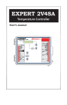
USER'S MANUAL
M 890-00373
rev. 01
K 895-000216
rev. 00
TABLE OF CONTENTS
PRECAUTIONS ............................................................ 4
FEATURES .................................................................. 5
LOCATION OF THE CONTROLS ..................................... 8
INSTALLATION .......................................................... 10
Mounting Instructions ................................................................ 10
Connections ............................................................................. 10
Motor Types ............................................................................ 12
TIME AND DATE FUNCTIONS ..................................... 13
MONITORING FUNCTIONS ......................................... 14
USER SETUP ............................................................. 15
TEMPERATURE SETTINGS ......................................... 24
Displaying Temperatures ............................................................ 24
Temperature Set Points .............................................................. 26
Temperature Curve .................................................................... 27
MINIMUM VENTILATION ............................................ 30
Principle of Operation ................................................................. 30
Minimum Ventilation Settings ..................................................... 32
Minimum Ventilation Speed Curve ............................................... 34
COOLING .................................................................. 37
Outside Temperature Compensation .............................................
Merging Fan Stages ...................................................................
De-icing Stage 2 Fans ................................................................
Mist Cooling .............................................................................
Relative Humidity (RH) Compensation ..........................................
42
45
48
50
53
HEATER SETTINGS .................................................... 57
Regular Heating Stages .............................................................. 57
Zoned Heating Stages ................................................................ 58
Heating Stages using Timers ....................................................... 59
2
EXPERT 2V4SA rev.01
EXPERT 2V4SA
TIMER-BASED AIR INLET ........................................... 62
Principle of Operation ................................................................. 62
Settings ................................................................................... 67
Manual Opening of the Air Inlet ................................................... 71
POTENTIOMETER-BASED AIR INLET ........................... 72
Principle of Operation .................................................................
Settings ...................................................................................
Manual Opening of the Air Inlet ...................................................
Static Pressure Compensation on the Inlet Opening ........................
72
75
79
80
0-10V OUTPUTS ........................................................ 83
0-10V
0-10V
0-10V
0-10V
Ventilation Output ...........................................................
Heating Output ...............................................................
Chimney Damper Output ..................................................
Outputs: Heat Mat Settings ..............................................
84
88
91
94
ALARM SETTINGS ..................................................... 96
Temperature Alarms ...................................................................
Defective Probe Alarm ................................................................
Defective Potentiometer Alarm .....................................................
Water Spill Alarm ......................................................................
96
98
98
99
TEST MODE ............................................................ 100
TECHNICAL SPECIFICATIONS .................................. 101
MEMORY CARD ...................................................... 102
INSTALLATION REPORT ........................................... 104
INDEX .................................................................... 107
EXPERT 2V4SA rev.01
3
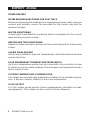
PRECAUTIONS
We strongly recommend installing supplementary ventilation as
well as a backup thermostat on at least one fan stage (refer to the
wiring diagram enclosed with this user's manual to connect the
thermostat).
Although overload and overvoltage protection is provided for the
controller circuits, we recommend installing additional protection
devices in the electrical panel.
The room temperature where the controller is located MUST
ALWAYS REMAIN BETWEEN 32°F AND 104°F (0°C TO 40°C).
To avoid exposing the controller to harmful gases or excessive
humidity, it is preferable to install it in a corridor.
DO NOT SPRAY WATER ON THE CONTROLLER
FOR CUSTOMER USE
Enter the serial number located on
the side of the controller below for
future reference.
Model number: EXPERT 2V4SA
Serial number:
4
EXPERT 2V4SA rev.01
FEATURES
The EXPERT 2V4SA is an electronic device used for environmental control
in livestock buildings. It allows the user to maintain a specified target
temperature by controlling the operation of ventilation and heating
equipment. Two stages of variable fans and four stages of either heaters,
mist or ON/OFF fans can be controlled. The main features of the
EXPERT 2V4SA are as follows:
LCD DISPLAY
An LCD display provides an efficient interface for displaying, monitoring
and adjusting parameter values.
PILOT LIGHTS
Pilot lights indicating the state of outputs allow the user to monitor the
operation of the system without having to enter the building.
REMOVABLE CONNECTORS
Input connectors can be removed from the main board. These removable
terminal blocks simplify wiring the various inputs.
MINIMUM VENTILATION CYCLE
When ventilation is not required for reducing room temperature, the first
and second fan stages can be operated either continuously or intermittently to reduce the level of humidity and supply oxygen to the room.
TEMPERATURE AND MINIMUM VENTILATION CURVES
The controller can be set to automatically change the temperature set
point and the minimum ventilation cycle over a given period of time, in
accordance with the user's requirements, by specifying a temperature curve
and a minimum ventilation cycle curve with up to ten different points each.
CHOICE OF TEN MOTOR TYPES
The variation in motor speed resulting from a change in voltage will depend
on the make and capacity of the motor. In order to achieve a high degree
of compatibility between controller and motor, the user can choose from
among ten different motor types, thus ensuring that the correct voltage is
supplied.
EXPERT 2V4SA rev.01
5
EXPERT 2V4SA
ZONED HEATERS
PROBE READINGS RECORDED FOR PAST DAYS
Minimum and maximum readings from temperature probes, static pressure
sensors and humidity sensor are recorded for the current day and the
previous six days.
WATER MONITORING
A pulse input is provided for monitoring water consumption for the current
days and the previous six days.
HEATER RUN TIME MONITORING
Heater run times are kept in memory for the current day and for the previous
6 days.
ALARM MANAGEMENT
Alarms are provided for high-low temperatures, defective probes and other
system functions.
FOUR INDEPENDENT TEMPERATURE PROBE INPUTS
Up to four temperature probes can be connected to the controller in order
to obtain a more accurate reading of the average room temperature and a
faster reaction time.
OUTSIDE TEMPERATURE COMPENSATION
Fan stages are automatically adjusted according to the outside temperature. It ensures a better stability in the room temperature.
0-10V OUTPUT
A 0-10V output can be used to control supplementary ventilation or heating equipment. This output can also control chimney dampers.
6
EXPERT 2V4SA rev.01
EXPERT 2V4SA
HUMIDITY COMPENSATION
The controller can use different mechanisms to reduce the humidity level.
When the humidity level is too high, it can disable the mist stage, enhance
the minimum speed of stage 1 fans and/or activate heating units in timer
mode.
STATIC PRESSURE CONTROL
A static pressure input is provided to control the static pressure level by
opening and closing the air inlets (on condition that the air inlet uses a
potentiometer). When the pressure level is too high, the inlet opens to compensate. When the pressure level is too low, the air inlet closes.
CONTROL OF AIR INLET MOVEMENT
The movement of air inlets can be coordinated with the operation of the
fans using a potentiometer located on the panel drive or with a timer. This
allows the air inlets to be adjusted correctly, without the influence of uncontrollable factors such as wind or air from adjoining rooms.
PASSWORD PROTECTION
A password allows to restrict access to the controller's setup functions.
BACKUP BATTERY
A backup battery allows the unit to keep time in case of a power failure.
OVERLOAD AND OVERVOLTAGE PROTECTION
Resettable fuses are provided at low-voltage inputs and outputs of the
controller to protect its circuitry in the case of an overload or overvoltage.
COMPUTER CONTROL
The controller can be connected to a computer, thus making it possible to
centralize the management of information and diversify control strategies.
TEST MODE
A test mode allows you to simulate temperature changes and verify
controller's performance.
EXPERT 2V4SA rev.01
7
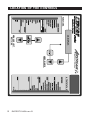
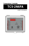
LOCATION OF THE CONTROLS
FUNCTIONS
LCD DISPLAY
MENU SELECT
BUTTONS
ARROW KEYS
OUTPUT STATUS
EXPERT 2V4SA rev.01
8
EXPERT 2V4SA
Led Display: The display on the top right corner of the faceplate shows the
current room temperature averaged over all selected room temperature
probes. It can also display the static pressure level or the air inlet position.
LCD Display: The LCD display at the left
Room T°
76.9°F
shows the current readings and parameters
Pr.Act:1234
to be adjusted when you select a function.
The three keys beside the display are used to edit parameters and step
through the display. When the parameters for a given function cannot all
be presented at once on the display, arrows are displayed on the right hand
side to indicate that additional parameters can be displayed using the
arrow keys
. After 15 minutes of inactivity, the display returns to the
current temperature display.
Adjustment and navigation arrow keys: The arrow keys that are located
next to the LCD display are used to scroll menus when all parameters
cannot be presented all at once. These keys are also used to modify a
parameter's value once the MODIFY have been pressed.
Status Leds: The status leds that indicates which function is actually
selected.
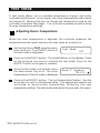
Adjusting a Parameter: Press on the "MODIFY" button to edit a parameter, the parameter will then flash on the display. This means that it can
now be modified. Use the up and down-arrow keys that are located beside
the display to modify the parameter's value.
Output Status LEDs: LEDs at the right side of the control panel give the
status of each output. When the LED is turned on, the output is activated;
when the LED is turned off, the output is deactivated.
EXPERT 2V4SA rev.01
9
INSTALLATION
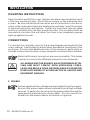
MOUNTING INSTRUCTIONS
Open the latch and lift the cover. Remove the black caps located on each
of the four mounting holes. Mount the enclosure on the wall using four
screws. Be sure the electrical knockouts are at the bottom of the enclosure in order to prevent water from entering the controller. Insert the screws
in the mounting holes and tighten. Fasten the four black caps provided
with the controller onto the four mounting holes. The enclosure must be
mounted in a location that will allow the cover to be completely opened
right up against the wall.
CONNECTIONS
To connect the controller, refer to the wiring diagram enclosed with this
user's manual. Use the electrical knockouts provided at the bottom of the
enclosure. Do not make additional holes in the enclosure, particularly on
the side of the enclosure when using a computer communications module.
Note that the input connectors are now removable. This makes
it easier to connect the different elements to the terminals.
ALL WIRING MUST BE DONE BY AN AUTHORIZED ELECTRICIAN AND MUST COMPLY WITH APPLICABLE CODES,
LAWS AND REGULATIONS. BE SURE POWER IS OFF BEFORE
DOING ANY WIRING TO AVOID ELECTRICAL SHOCKS AND
EQUIPMENT DAMAGE.
:$51,1*
1. PROBES
Probes operate at low voltage and are isolated from the supply.
Be sure that probe cables remain isolated from all high voltage
sources. In particular, do not route the probe cables through the
same electrical knockout as other cables. Do not connect the
shield from the probe cable to a terminal or a ground.
10 EXPERT 2V4SA rev.01
EXPERT 2V4SA
Extending a probe: Each probe can be extended up to 500 feet (150 meters).
To extend a probe:
Use a shielded cable of outside diameter between 0.245 and 0.260 in
(6.22 and 6.60 mm) (the cable dimensions should not be under 18
AWG) to ensure the cable entry is liquid tight. Do not ground the
shielding.
It is preferable to solder the cable joint to ensure a proper contact
between the two cables.
CAUTION: Do not run probe cables next to other power cables. When
crossing over other cables, cross at 90°.
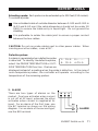
Defective probes:
An alarm is generated when a defective probe
1: 74.2 2:----is detected. To identify the defective probe,
3: 72.3 4:73.0
select the PROBE TEMPERATURE or OUTSIDE TEMPERATURE function. Dashes are
displayed instead of a reading when the probe is defective. In the case of
room temperature probes, the controller will operate according to the
temperature of the remaining probes.
2. ALARM
There are two types of alarms on the
market. One type activates when current
is cut off at its input, whereas the other
activates when current is supplied at its
input. For an alarm of the first type, use
the NC terminal as shown on the wiring
diagram. For an alarm of the second type,
use the NO terminal.
M
N
O
NO
C
NC
ALARM
EXPERT 2V4SA rev.01
11
EXPERT 2V4SA
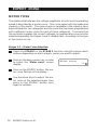
MOTOR TYPES
The relationship between the voltage supplied to a motor and its operating
speed is described by a motor curve. This curve varies with the make and
capacity of the motor. The various motors available in the industry have
been divided into ten categories and the controller has been programmed
with a different motor curve for each of these categories. To ensure that
the controller supplies the correct voltages, an appropriate curve must be
selected separately for stages 1 and 2 variable fans, according to the type
of fan motors in use.
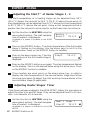
Stages 1-2 : Motor Curve Selection:
Select the STAGE 1 or the STAGE 2 function using the menu select
buttons depending on which stage's motor you want to adjust.
Press on the down-arrow key, in order
to select the "Motor curve" screen
display.
Press on the MODIFY button, the motor curve flashes on the display.
Use the arrow keys to adjust the motor curve of the selected stage then
press on the MODIFY button once
again to validate.
12 EXPERT 2V4SA rev.01
Motor curve
4
TIME AND DATE FUNCTIONS
Set the function to TIME & DATE using
the menu select buttons. The current
time and date are displayed.
Press on the MODIFY button. The hours
flash on the display. Use the arrow keys
to set the hours. Press on the MODIFY
button. The minutes flash on the display.
Use the arrow keys to set the minutes.
Press on the MODIFY button once again.
The seconds flash on the display. Use
the arrow keys to adjust the seconds to
the desired value.
12:00:00 PM
01/01/200X
Press on the MODIFY button. The month
flashes. Use the arrow keys to set the
month. Press the Modify button. The day
flashes. Use the arrow keys to set the
day. Press the Modify button once
again, the year flashes. Use the arrow
keys to set the year.
EXPERT 2V4SA rev.01
13
MONITORING FUNCTIONS
1
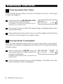
Viewing Heater Run Times
The controller has an history in which the heater run times , for the past
6 days, are logged in.
Set the function to HEATER RUN TIME
using the menu select buttons.
Accessible if at least one heating stage is
enabled in the USER SETUP.
Heater 1
01/01/0X
2:30
The current run time of the first heating stage is displayed along with
the time and date.
Keep pressing the down-arrow key to scroll the display and look at the
run times of this heater for the past 6 days.
2
Viewing Water Consumption
The controller provides a pulse input to monitor the water consumption.
The water consumption is logged into an history for the current day and for
the past 6 days.
Set the function to WATER using the
menu select buttons. Today's water consumption is displayed.
01/31/0X
01/30/0X
1241l
6189l
Available if the water counter is enabled in the
USER SETUP.
Press the down-arrow key to scroll the display. The water consumption for the past 6 days is displayed.
14 EXPERT 2V4SA rev.01
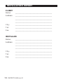
USER SETUP
The following section describes how to customize the controller for your
particular application. Normally, this setup needs to be done only once. A
template is available at the end of this manual to write down all these
parameters.
It is recommended to clearly define every stage that is going to
be used by your controller. Select the proper stage option on the
table below.
STAGES COMBINATIONS
STAGE 1
STAGE 2
STAGE 3
STAGE 4
STAGE 5
STAGE 6
OPTION 1
VAR 1
VAR 2
FAN 1
FAN 2
FAN 3
FAN 4
OPTION 2
VAR 1
VAR 2
FAN 1
FAN 2
FAN 3
MIST
OPTION 3
VAR 1
VAR 2
FAN 1
FAN 2
FAN 3
H EAT 1
OPTION 4
VAR 1
VAR 2
FAN 1
FAN 2
MIST
H EAT 1
OPTION 5
VAR 1
VAR 2
FAN 1
FAN 2
H EAT 2
H EAT 1
OPTION 6
VAR 1
VAR 2
FAN 1
MIST
H EAT 2
H EAT 1
1. Set the function to USER using the menu select buttons.
The following parameters are presented below in the order they appear on the
display. The installer's password must first be entered to access these menus. To
modify a parameter, press on the MODIFY button then use the arrow keys to
change it. When you are finished adjusting a parameter, press on the MODIFY
button to validate the new value and to return to the display mode. Press on the
down-arrow key to move to the next parameter.
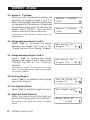
2. Time of Day Format:
Select the time format:
AM-PM or 24 hours mode.
Time format
AM-PM
3. Temperature Units:
Select the temperature units:
Fahrenheit (F°) of Celsius (°C) degrees.
Temp. units
°F
EXPERT 2V4SA rev.01
15
EXPERT 2V4SA
4. # of Temperature Sensors in the Room: Set
the total number of temperature sensors
that are wired to the controller. Up to 4
temperature sensors can be selected.
5. Room Probes:
Select which of the room sensors are used
to be part of the average room
temperature. Blinking digits represent
probes that are selected to be part of the
average room temperature. At least one
temperature probe must be selected.
Press on the MODIFY button then set each
probe status by using the arrow keys.
6. Use Water Meter:
Select "Yes" if a water meter is
connected to the controller.
7. Water Meter Units:
Select the water units: Gallons or liters.
Accessible if the water meter is enabled above.
8. Water Meter Calibration:
Set the # of gallons or liters per pulse.
Accessible if the water meter is enabled above.
9. Use Humidity Sensor:
Select "Yes" if a relative humidity
sensor is connected to the controller.
10. Humidity Compensation on Min. Speed:
Select "Yes" to enable the compensation of stage 1 fans' speed, according to
the humidity level (refer to the Relative
Humidity Compensation chapter).
Accessible if the humidity sensor is enabled
above.
16 EXPERT 2V4SA rev.01
#T° sensors in
the room:
4
Room probes
1234
Room probes
1
On
Use water meter?
No
Water meter units
lit
Water unit/pulse
1
Use humidity
sensor?
No
Rh influence on
Min. Speed?
No
EXPERT 2V4SA
11. Use Outside Temperature Sensor:
Select "Yes" if an outside temperature
sensor is connected to the unit.
Use Out T°
sensor?
12. Outside T° Compensation on Min. Speed:
Select "Yes" to activate the outside
temperature compensation on the
minimum speed of stage 1 fans (refer to
the Outside T° Compensation chapter).
Out T° compens.
Min Speed?
No
Yes
Accesible if the outside temperature sensor is
enabled above.
13. Use Outside T° Compensation on Stg 1:
Select "Yes" to activate the outside
temperature compensation on the # of
degrees to 100% of stage 1 (refer to
the Outside T° Compensation chapter).
Out T° compens.
stage1?
No
Accessible if the outside temperature sensor
is enabled above.
14. Use Outside T° Compensation on Stg 2:
Select "Yes" to activate the outside
temperature compensation on # of degrees to 100% of stage 2 (refer to the
Outside T° Compensation chapter).
Out T° compens.
stage2 ?
No
Accessible if the outside temperature sensor
is enabled above.
15. Winter's Reference Temperature:
Set the temperature that indicates the
beginning of the winter season.
Accessible if the compensation is enabled in
#12, 13 or 14 above.
16. Summer's Reference Temperature:
Set the temperature that indicates the
beginning of the summer season.
Accessible if the compensation is enabled in
#12, 13 or 14 above.
Outside T° in
winter:
41.0°F
Outside T° in
summer:
59.0°F
EXPERT 2V4SA rev.01
17
EXPERT 2V4SA
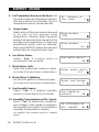
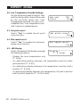
17. Use the Static Pressure Sensor:
Select "Yes" if a static pressure sensor
is connected to the controller.
18. Use the Static Pressure Compensation:
Select "Yes" if to activate the static
pressure compensation on the opening
of the potentiometer-based inlet (refer
to the S.Pressure Compensation section).
Use Stat. P
sensor?
Yes
Use Stat. P
compens.?
No
Accessible if the static pressure sensor is enabled above and if the inlet uses a potentiometer (see below).
19. Heaters and 0-10V Output:
Set the number of heating stages, in
accordance with you stages' definition,
as shown at the beginning of this
chapter. Up to two heater stages can be
activated.
#Heaters:
#0-10V
1
2
Set the number of 0-10V outputs to the desired value. Adjustable between 0 and 1 output.
20. 0-10V Output # 1 Used for:
Select the proper operation for the first
0-10V output: Ventilation / Heating /
Heat mat / Chimney damper.
0-10V 1 used for
Ventilation
Accessible if a 0-10V output is enabled above.
21. 0-10V follows the Set Point ? :
Select "Yes" if the start temperature of
0-10V 1 follows
the 0-10V output is related to the set
setpoint?
No
point. This means that when the set point
changes, the start temperature is adjusted by the same amount. Select "No" to use an absolute start temperature on this output.
Accessible if a 0-10V output is enabled above.
18 EXPERT 2V4SA rev.01
EXPERT 2V4SA
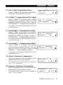
22. 0-10V or 10-0V Signal:
Select the proper signal of the
0-10V output (0-10V or 10-0V).
Accessible if a 0-10V output is enabled above.
23. Use Mist:
Select "Yes" to activate the mist stage.
0-10V 1 Mode
0-10V
Use Mist?
Use Inlet?
No
Yes
24. Use Inlet:
Select "Yes" to activate the air inlet.
25. Inlet Mode:
Select "Pot" if the inlet moves according to a potentiometer; select "Time" if
the inlet moves according to a timer.
Inlet Mode
Pot
Accessible if the air inlet is enabled above.
26. Use a timer on heating stages:
Select "Yes" to activate heaters in a
timer mode, according to the room
temperature.
Use heaters on
timer ?
Yes
Accessible if a heating stage is enabled above.
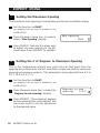
27. Number of intermediate steps:
If the opening of the air inlet is based on
a timer, select the number intermediate
opening steps that are performed during a variable stage
(0-2 intermediate steps).
# Inter. Steps
2
Accessible if the opening of the inlet is base on a timer
28. Zoned or standard heaters:
This function allows to run the heating
Use Zoned heater?
outputs according to the temperature
No
reading of chosen temperature sensors;
the heating outputs' operation becomes
based on the average reading of these sensors instead of being based
on the average room temperature.
Accessible if two heating stages are enabled above.
EXPERT 2V4SA rev.01
19
EXPERT 2V4SA
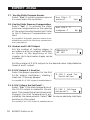
29. Heater 1 - 2 probes:
Select on which temperature sensors the
operation of heating stages 1 and 2 is
based. Blinking digits represent probes that
are assigned for this purpose. At least one
temperature probe must be selected per
heater. Press MODIFY then set each
probe's status with the arrow keys.
Heater 1 probes
1234
Heater 2 probes
1234
Accessible if the heaters' zoned mode is enabled above.
30. Merge between stages 1 and 2:
Select "Yes" if to enable the merge
between fan stages 1&2 (refer to the
"Merge" section of the "Cooling" chapter).
31. Merge between stages 2 and 3:
Select "Yes" to enable the merge
between fan stages 2 and 3 (refer to the
"Merge" section of the "Cooling"
chapter).
Use merge for
stages 1-2
No
Use merge for
stages 2-3
No
Accessible if stage 3 is used as a fan stage.
Refer to the stage option table at the beginning of this chapter.
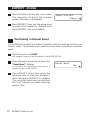
32. De-icing Stage 2:
Select "Yes" if to enable the de-icing feature on fan stage 2.
33. Use Night Set Point:
Select "Yes" to enable the night set point.
34. Night Set Point Starts at:
Select the time at which the night set
point starts being used by the controller.
Accessible if the night set point is enabled
above.
20 EXPERT 2V4SA rev.01
Use de-icing on
stage 2?
No
Use night setp?
Yes
Night setp at
8:00P
EXPERT 2V4SA
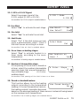
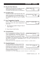
35. Day Set Point Starts at:
Select the time at which the day set point
starts being used by the controller.
Accessible if the night set point is enabled above.
36. Transition Time:
Set the transition time between day and
night set points to the desired value. It
can be adjusted from 15 to 120 minutes.
Day setp at:
7:30A
Transition time
60 min
Accessible if the night set point is enabled
above.
37. Low Temperature Override:
Select "Yes" to activate the following
functions when the room temperature
is too low:
Low T° override
Yes
1. Decrease the speed of stage 1 fans &
stop stage 2;
2. Close the air inlet further.
38. Override Below:
Set the temperature below which the
Override below
"Low temperature override" options
70.0°F
start being effective. This temperature
is directly related to the set point. When
a change in the set point occurs, the override's start temperature is
adjusted consequently. Adjustable from 1°F to 40°F (0.6 to 22.2°C)
below the set point.
Accessible if the "Low temperature override" feature is enabled above.
39. Override Stops at:
Set the temperature above which the
Override stop at
override functions stop when the room
75.0°F
temperature increases. This temperature is directly related to the set point.
When a change in the set point occurs, the override's stop temperature
is adjusted consequently.
Accessible if the "Low temperature override" feature is enabled above.
EXPERT 2V4SA rev.01
21
EXPERT 2V4SA
40. Low Temperature Override Settings:
Set the minimum speed of stage 1 fans
and the inlet position that will be used
by the controller when the "Low
Temperature override" function is on.
Available if the "Low temperature override" feature is enabled above.
41. Set point curve?
Select "Yes" to enable the set point
curve function.
42. Min speed curve?
Select "Yes" to enable the minimum
speed curve function.
43. LED Display:
Select the desired LED display amongst
the following options:
Min spd
Inlet
15%
0%
Set point curve?
Yes
Min speed curve?
Yes
Display:
T° & Inlet
- Display the room temperature only
(T° Only);
- An alternating display between the temperature and the static
pressure level (T° & SP);
- An alternating display between the temperature and the inlet's
position (T° & Inlet);
- An alternating display between the temperature, the inlet's position
and the static pressure (T° & SP & Inlet).
22 EXPERT 2V4SA rev.01
EXPERT 2V4SA
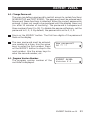
44. Change Password:
The user can define a password to restrict access to certain functions
(USER SETUP and TEST MODE). The password must be entered each
time one of these functions is selected. When the correct password is
entered, it does not need to be reentered until the display times out
(i.e. after 15 minutes of inactivity). The password is a sequence of
three numbers from 0 to 99. To disable the password feature, set the
password to 0, 0, 0. By default, the password is set to 0, 0, 0.
Press on the MODIFY button. The first two digits of the password
flash on the display.
The new password must be entered,
one number at a time. Use the arrow
keys to enter the first number. Press
on the MODIFY button to step to the
next number. Use the arrow keys to
enter the second number, etc.
44. Program Version Number:
The program version number of the
controller is displayed.
New password?
00 ** **
EXPERT 2V4SA
Version X.X
EXPERT 2V4SA rev.01
23
TEMPERATURE SETTINGS
DISPLAYING TEMPERATURES
The controller has an history in which the minimum and maximum
temperature readings of the current day and of the past 6 days are logged
in, along with the time and date. These values are logged into the history
at midnight everyday.
1
Viewing the Room Temperature
The room temperature is the average reading of the temperature probes
that have been assigned for this purpose during the USER SETUP.
Set the function to ROOM TEMPERATURE using the menu select buttons. The
average room temperature is displayed.
The probes that are assigned to be part
of the average temperature flash on the
display.
Press the down-arrow key. Today's
minimum temperature is displayed along
with the time and date.
Room T°
76.5 °F
Pr.Act:1234
Room T° 01/01/0X
Min 72.2 1:10A
Press the down-arrow key once again. Today's maximum temperature is displayed along with the time and date.
Keep pressing on the down-arrow key to look at the minimum and
maximum temperature readings that have been recorded each day for
the past 6 days.
24 EXPERT 2V4SA rev.01
EXPERT 2V4SA
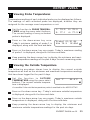
2
Viewing Probe Temperatures
Temperature readings of each individual probe can be displayed as follows.
The readings of each activated probe are displayed, whether they are
assigned for the average room temperature or not.
Set the function to PROBE TEMPERATURES using the menu select buttons.
The current reading of every activated
probe is displayed.
1: 74.3
3: 77.1
Press on the down-arrow key once.
Today's minimum reading of probe 1 is
displayed, along with the time and date.
Probe1 01/01/0X
Min 73.3 12:30A
2: 75.0
4: 77.3
Press on the down-arrow key once again. Today's maximum reading
of probe 1 is displayed, along with the time and date.
Keep pressing the down-arrow key to display the minimum and maximum temperature readings of the past 6 days for each remaining probe.
3
Viewing the Outside Temperature
The following procedure shows how to display the current outside
temperature as well as the minimum and maximum temperature readings
that have been logged for the past 6 days.
Set the function to OUTSIDE
TEMPERATURE using the menu select
buttons. The current outside temperature is displayed.
Out T°
55.2°F
Accessible if the outside temperature probe is enabled in the USER SETUP.
Press on the down-arrow key . Today's minimum outside temperature
is displayed, along with the time and date.
Press on the down-arrow key once again. Today's maximum outside
temperature is displayed, along with the time and date.
Keep pressing the down-arrow key to display the minimum and
maximum outside temperature readings for the past six days.
EXPERT 2V4SA rev.01
25
EXPERT 2V4SA
TEMPERATURE SET POINTS
The temperature set point is the target room temperature. It can be
adjusted from -40.0°F to 100°F (-40.0°C to 37.8°C). The temperature
curve must be disabled to adjust this target temperature. A night set point
can also be enabled, in order to maintain a different target temperature
during night time.
ADJUSTING THE MAIN TEMPERATURE SET POINT
Set the function to SET POINT / CURVE
using the menu select buttons. The current set point is displayed.
Setp
75.0°F
Press MODIFY then use the arrow keys to change the set point.
The set point can only be modified while the temperature curve is disabled.
Refer to the following section to disable the curve.
ADJUSTING THE NIGHT SET POINT
This is the target room temperature during night. It can be adjusted from
-40.0°F to 100°F (-40.0°C to 37.8°C). The night set point is directly
related to the main set point, which means that if a change in the main set
point occurs, the night set point is adjusted consequently. If the temperature curve is enabled, the night set point follows the same variations as the
day set point.
Set the function to SET POINT / CURVE using the menu select buttons. The current set point is displayed.
Press the down-arrow key to select the
night set point.
Available if the night set point is enabled in
the USER SETUP.
Night Setpoint
75.0°F
Press MODIFY. The night set point flashes on the display. Use the
arrow keys to adjust it to the desired value.
26 EXPERT 2V4SA rev.01
EXPERT 2V4SA
TEMPERATURE CURVE
The temperature curve allows an automatic adjustment of the target room
temperature over time. The set point curve function must first be enabled
in the USER SETUP.
Temperature Curve
SET POINT
TEMPERATURE
T° 1
T° 2
T° 3
T° 4
T° 5
T° 6
T°7
T°8
T° 9
T° 10
DAY 4 DAY 15
DAY 21
DAY 30
DAY 36
DAY 45
DAY 55
DAY70
DAY 80
DAY 100
DAYS
A curve is defined using up to 10 points. Each point specifies a day number
and a set point for that day. Once the points of the curve are defined, the
curve must be activated. The controller will change the temperature set
point every hour in a linear fashion between consecutive points of the
curve. When the last point of the curve is reached, the temperature set
point for that day is maintained until the curve is reactivated.
NOTES:
i)
All ten points of the curve must be specified. If ten points are not
needed, repeat the last temperature value for each unnecessary point.
ii)
Certain restrictions apply to reduce the risk of errors:
- The highest possible day number is 365.
- Decreasing day numbers are not allowed.
- Increasing temperatures are not allowed.
EXPERT 2V4SA rev.01
27
EXPERT 2V4SA
1
Specifying the Curve
Set the function to SET POINT / CURVE using the menu select buttons.
The current set point is displayed.
Press the down-arrow key to select
the first point of the curve. The day at
which this curve point starts being
used and the set point for that day are
displayed.
1. day
1
Setp
75.0°F
Accessible if the set point curve is enabled in the USER SETUP.
Press MODIFY then use the arrow keys to select the day and the set
point associated with the first point of the curve.
Press the down-arrow key to display and adjust all points of the curve.
2
Activating / Deactivating the Temperature Curve
Set the function to SET POINT / CURVE using the menu select buttons.
The current set point is displayed.
Press the down-arrow key to select the
curve status.
Accessible if the set point curve is enabled
in the USER SETUP.
Curve status
Off
Press MODIFY. The curve status flashes on the display. Use the arrow
keys to enable or to disable the curve. Press MODIFY once again to
validate.
28 EXPERT 2V4SA rev.01
EXPERT 2V4SA
3
Setting the Day Number
The following menu indicates the day that is currently being used by the
curve. This day can also be modified in order to move forward or backward
on the curve. This day number usually refers to the animal age.
Note that a change in the day number also affects the minimum
speed curve (refer to the Minimum Ventilation chapter).
Set the function to SET POINT / CURVE using the menu select buttons.
The current set point is displayed.
Press on the down-arrow and select the
"Current day" screen display.
Accessible if the set point curve or if the minimum speed curve is enabled in the USER SETUP.
Current day
9
Press MODIFY. The current day flashes
on the display. Use the up and downarrow keys to set it to the proper value.
EXPERT 2V4SA rev.01
29
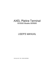
MINIMUM VENTILATION
Principle of Operation
When the room temperature is below the set point, stage 1 fans operate
according to a minimum ventilation cycle. Running fans even though ventilation is not required for reducing the room temperature is useful to
reduce humidity levels and supply oxygen to the room. It also prevents the
fans from freezing in winter.
NOTE: The controller supplies maximum voltage to the variable-speed
fans for 2 seconds immediately following each start-up.
MINIMUM VENTILATION TIMER:
The minimum ventilation timer is composed of a running time (On
Time) and of a stop time (Off Time) as illustrated below:
On time: Stage 1 fans run at their minimum speed. The pilot light
of stage 1 is lit while these fans are running in minimum ventilation.
Off time: Stage 1 fans are stopped.
MIN. VENT.
CYCLES’
FAN SPEED
ON TIME
OFF
OFF
TIME
NOTES:
•
To run stage 1 fans continuously at their minimum speed, set the off
time to zero and the On time to any value other than zero.
•
To disable minimum ventilation cycles, set the On time to zero and the
Off time to any other value.
•
To run stage 1 fans intermittently, set the On and Off time to the
proper values.
30 EXPERT 2V4SA rev.01
EXPERT 2V4SA
Stage 2 in Minimum Ventilation
Stage 2 fans can be used to provide minimum ventilation as shown on the
following graphic:
Stage 2 Fans in Minimum Ventilation
VENTILATION
STAGE 2 FANS
RUN FOLLOWING
THE TIMER OF STAGE 1.
STAGE 2
(FULL SPEED)
STAGE 2
(MIN. SPEED)
STAGE 2
(OFF)
0.3°F
STAGE 1
(MIN. SPEED)
STAGE 1
(OFF)
STAGE 1
MINIMUM VENT.
0.3°F
# OF DEGREES
TO REACH 100%
OF STAGE 1
STAGE 1
START TEMP.
0.3°F
# OF DEGREES
TO REACH 100%
OF STAGE 2
TEMPERATURE
STAGE 2
START TEMP.
-
When the room temperature decreases below Stage 2 start temperature, stage 2 fans run intermittently according to the same timer as
the one used by stage 1.
-
When the room temperature increases above Stage 2 start temperature, stage 2 fans start increasing in speed continuously.
Low Temperature Override:
If the room temperature gets too cold while the controller is in minimum
ventilation, low temperature override functions can be enabled to reduce
the speed of stage 1 fans and to stop stage 2. This allows reheating the
room faster. Low temperature override functions must be enabled in the
USER SETUP.
EXPERT 2V4SA rev.01
31
EXPERT 2V4SA
Minimum Ventilation Settings
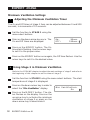
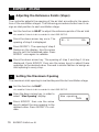
1
Adjusting the Minimum Ventilation Timer
The On and Off times of stage 1 fans can be adjusted between 0 and 900
seconds, in increments of 15 seconds.
Set the function to STAGE 1 using the
menu select buttons.
Press on the down-arrow key once. The
On and Off times are displayed.
On:
Off:
30sec
120sec
Press on the MODIFY button. The On
time starts flashing. Use the arrow keys
to set it to the proper value.
Press on the MODIFY button once again, the Off time flashes. Use the
arrow keys to set it to the desired value.
2
Using Stage 2 in Minimum Ventilation
Refer to the COOLING chapter to adjust the main settings of stage 2 and refer to
the beginning of this chapter to set the timer of stage 1.
Set the function to STAGE 2 using the menu select buttons. The start
temperature of stage 2 is displayed.
Press on the down-arrow key in order to
select the "Min Ventilation" display.
Press on the MODIFY button. The status flashes on the display. Press on the
up-arrow key to activate the minimum
ventilation on stage 2 or press on the
down-arrow key to deactivate it.
32 EXPERT 2V4SA rev.01
Min Ventilation.
On
EXPERT 2V4SA
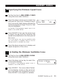
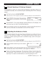
3
Adjusting the Minimum Speed of Stage 1
The minimum speed of stage 1 fans can be adjusted from 10 to 100%.
Note that the minimum speed curve must be turned off in order to adjust
this value.
Set the function to MIN. SPEED / CURVE using the menu select buttons. The minimum speed of stage 1 fans is displayed.
Press MODIFY then use the arrow keys to set the minimum speed to
the desired value.
This value can only be modified while the minimum ventilation curve is disabled.
Refer to the following section to disable the curve.
EXPERT 2V4SA rev.01
33
EXPERT 2V4SA
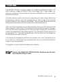
Minimum Ventilation Speed Curve
It is possible to define a curve to automatically adjust the minimum speed
of stage 1 fans, over a given period of time. This speed curve is defined by
ten points. Each point specifies a day number and a fan speed for that day.
Once the points are defined, the curve must be activated. This function
must first be enabled in the USER SETUP.
Minimum Ventilation
Speed Curve
STAGE 1 MIN.
SPEED (%)
SPEED 10
SPEED 9
SPEED 8
SPEED 7
SPEED 6
SPEED 5
SPEED 4
SPEED 3
SPEED 2
SPEED 1
DAY 1
DAY 5
DAY 10
DAY 17
DAY 25
DAY 35
DAY 40
DAY 60
DAY 80
DAY 100
DAYS
Once the minimum ventilation speed curve is activated, the controller adjusts the minimum speed of stage 1 fans every hour in a linear fashion
between two consecutive points. When the last point of the curve is reached,
the curve is deactivated. The controller maintains the minimum speed
specified for this point until the curve is reactivated
NOTES:
i)
All ten points of the curve must be specified. If ten points are not
needed, repeat the last speed value for each unnecessary point.
ii)
Certain restrictions apply to reduce the risk of errors:
- The highest possible day number is 365.
- Decreasing day numbers are not allowed.
- Decreasing minimum speeds are not allowed.
34 EXPERT 2V4SA rev.01
EXPERT 2V4SA
1
Specifying the Minimum Speed Curve
Set the function to MIN. SPEED / CURVE
using the menu select buttons.
Press the down-arrow key to select the
first point of the curve. The day at which
this curve point starts being used and the
minimum speed of stage 1 fans for that
day are displayed.
1. day
Min Spd
1
30%
Accessible if the minimum speed curve is enabled in the USER SETUP.
Press MODIFY then use the arrow keys
to select the day and the minimum fan
speed associated which the first point of
the curve.
The curve points can only be modified while
the curve status is disabled. Refer to the following section to disable the curve.
Press the down-arrow key to display and
adjust all points of the curve.
2
Activating the Minimum Ventilation Curve
Set the function to MIN. SPEED / CURVE
using the menu select buttons.
Press the down-arrow key to select the
curve status display.
Accessible if the minimum speed curve is
enabled in the USER SETUP.
Curve status
Off
Press MODIFY. The curve status flashes
on the display. Press on the up-arrow
key to activate the temperature curve.
Press MODIFY once again to validate.
EXPERT 2V4SA rev.01
35
EXPERT 2V4SA
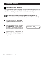
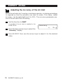
3
Setting the Day Number
The following menu indicates the day that is currently being used by the
curve. This day can also be modified in order to move forward or backward
on the curve. This day number usually refers to the animal age.
Note that a change in the day number will also affect the
temperature curve (refer to the Temperature Curve section).
Set the function to SET POINT /
CURVE using the menu select buttons.
Press on the down-arrow and select
the "Current day" screen display.
Accessible if the set point curve or if the
minimum speed curve is enabled in the
USER SETUP.
Press MODIFY. The current day
flashes on the display. Use the up and
down-arrow keys to set it to the
proper value.
36 EXPERT 2V4SA rev.01
Current day
9
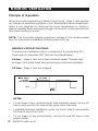
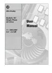
COOLING
The EXPERT 2V4SA controls 2 stages of variable-speed fans (stages 1-2)
and 4 optional stages of ON/OFF fans (fan stages 3-6). These stages operate in a sequence to increase the level of ventilation as the room temperature increases.
The user defines a start and a stop temperature for each stage. When the
temperature reaches the start temperature of a fan stage, the fans that
are associated to this stage are activated. They are deactivated when the
temperature decreases to their respective stop temperature.
Start and stop temperatures are defined with respect to the set point and
with respect to each other. This means that when the set point changes,
or if the start/stop temperature of a cooling stage changes, all consecutive
values are adjusted by the same amount. For example, if the set point is
increased by 1°F, the start temperatures of all consecutive fan stages are
increased by the same amount.
The minimum temperature difference between two start temperatures is
0.5°F (0.3°C). Note that stop temperatures cannot overlap the previous
stage's start temperature.
The graphic on next page illustrates the situation.
Refer to the MINIMUM VENTILATION chapter to set the minimum speed of stage 1 fans.
EXPERT 2V4SA rev.01
37
EXPERT 2V4SA
9(17,/$7,21
STAGE 6
STAGE 5
STAGE 4
STAGE 3
STAGE 2
STAGE 2
(FULL SPEED)
(MIN. SPEED)
STAGE 1
(MIN. SPEED)
MINIMUM
VENTILATION
CYCLE
0.3°F
# OF DEGREES
TO REACH 100%
OF STAGE 1
SET POINT
0.3°F
STAGE 3
STOP TEMP.
STAGE 6
START TEMP.
STAGE 6
STOP TEMP.
STAGE 5
START TEMP.
STAGE 5
STOP TEMP.
STAGE 4
START TEMP.
STAGE 4
STOP TEMP.
STAGE 3
START TEMP.
Fan Stages
# OF DEGREES
TO REACH 100%
OF STAGE 2
STAGE 2
START TEMP.
52207
38 EXPERT 2V4SA rev.01
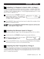
EXPERT 2V4SA
1
Adjusting # of Degrees to Reach 100% of Stage 1
This is the temperature interval over which stage 1 variable speed fans
increase in speed, proportionally to the temperature, in order to reach their
full speed (see the diagram above). It can be adjusted between 0.5°F and
20.0°F (0.3°C and 11.1°C).
Set the function to STAGE 1 using the
menu select buttons. The number of
degrees required to reach 100% speed
of stage 1 fans is displayed.
Degrees to 100%
2.0°F
Press MODIFY then use the arrow keys to adjust the number of degrees to the desired value.
Refer to the MINIMUM VENTILATION chapter to set the minimum speed of stage 1 fans.
2
Adjusting the Minimum Speed of Stage 2
The minimum speed of stage 2 fans can be adjusted from 10% to 100%.
Set the function to STAGE 2 using the menu select buttons.
Press on the down-arrow key to select
the "Minimum Speed" menu.
Minimum Speed
40%
Press on the MODIFY button, the minimum speed flashes on the display.
Use the arrow keys to set it to the desired value.
3
Adjusting the Start Temperature of Stage 2
The start temperature of stages 2 is the temperature at which the stage's
variable-speed fans start running continuously at their minimum speed
(refer to the previous diagram). It can be adjusted from 0 to 120°F (0 to
48.9°C) above the set point.
EXPERT 2V4SA rev.01
39
EXPERT 2V4SA
Set the function to STAGE 2 using the
menu select buttons. The start temperature of the selected stage is displayed.
StartT°: 80.0°F
Press on the MODIFY button, the start temperature of the selected
stage flashes on the display. Use the arrow keys to adjust it to the
desired value.
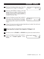
4
Adjusting # of Degrees to Reach 100% of Stage 2
This is the temperature interval over which the variable speed fans of
stage 2 increase in speed, proportionally to the room temperature, in order
to reach their full speed (see the diagram above). It can be adjusted between
0.5°F and 20.0°F (0.3°C and 11.1°C).
Set the function to STAGE 2 using the menu select buttons.
Press the down-arrow key twice, the
number of degrees to reach 100% of
fan stage 2 are displayed.
Degrees to 100%
2.0°F
Press on the MODIFY button, the value starts flashing. Use the arrow
key to adjust it to the desired value.
5
Adjusting Start/Stop Temperatures of Fan Stages 3-6
Set the start and stop temperatures of fan stages 3-6. The start temperature of these stages must be greater than: stage 2 start T°+ # of degrees
to 100% of stage 2 +0.5°F (0.3°C).
Set the function to STAGES 3-6 using
the menu select buttons. The start temperature of stage is displayed.
Stage 3
StartT°
84.0°F
Accessible if stage 3 is used as a fan stage.
Refer to stages option table in the USER SETUP.
Press MODIFY. The start temperature of stage 3 flashes on the display. Use the arrow keys to adjust the start temperature to the desired
value then press the MODIFY button to validate the new value.
40 EXPERT 2V4SA rev.01
EXPERT 2V4SA
Press on the down-arrow key. The stop
temperature of stage 3 is displayed.
StopT°
82.0°F
Press on the MODIFY button, the stop
temperature of stage 3 flashes on the
display. Use the arrow keys to adjust it
to the desired value. Press MODIFY to
validate the new value.
Press on the down-arrow key in order to
select the start temperature of stage 4.
Accessible if stage 4 is used as a fan stage.
Refer to stages option table in the USER SETUP
chapter.
Stage 4
StartT°
86.0°F
Follow the same procedure as described above to adjust the start and
stop temperatures of stages 4-6.
6
Viewing the Current Fan Speed of Stages 1-2
Set the function to STAGE 1, or STAGE 2 using the menu select buttons.
Press on the down-arrow key in order to
select the "Current speed" screen
display.
Current speed
100%
EXPERT 2V4SA rev.01
41
EXPERT 2V4SA
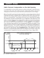
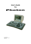
Outside Temperature Compensation
Outside temperature compensation functions allow adapting fan stage parameters in accordance with the outside temperature. This ensures better
stability in the room temperature.
Refer to the USER SETUP chapter to adjust summer & winter's
reference temperatures.
Outside Temperature Compensation on the Minimum
Speed of Stage 1
The minimum speed of stage 1 fans can automatically be adjusted
according to the outside temperature: as the outside temperature
decreases, the minimum speed of stage 1 fans decreases proportionally to compensate for the change:
-
The regular minimum speed is used when the outside temperature
is at or above summer's reference temperature.
The winter speed is used when the outside temperature is at or
below winter's reference temperature.
MINIMUM SPEED
OF STAGE 1 FANS
Outside Temperature Compensation
on the Minimum Speed of Stage 1 Fans
40%
(REGULAR
MIN SPEED)
THE MINIMUM SPEED
CHANGES DEPENDING
ON THE OUTSIDE
TEMPERATURE
WINTER T°
SUMMER T°
OUTSIDE
TEMPERATURE
Note that the minimum speed used in winter is directly related to
the regular minimum speed. This means that if a change occurs in
the regular minimum speed, the winter's minimum speed is automatically adjusted by the same value.
42 EXPERT 2V4SA rev.01
EXPERT 2V4SA
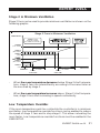
Outside Temperature Compensation on the "number of
degrees to 100%" of stages 1 & 2
The number of degrees to reach 100% of stages 1 & 2 can automatically
be adjusted according to the outside temperature. The user defines the
number of degrees to reach 100% for winter and for summer. The number
of degrees to reach 100% are then automatically adjusted as the outside
temperature changes.
If the # of degrees to reach 100% of stage 1 or 2 changes, start
temperatures of all consecutive fan stages are adjusted by the
same amount.
# OF DEGREES
TO REACH 100% OF
FAN SPEED
Outside Temperature Compensation
on the “# of degrees to reach 100 %”
of fan stages 1 & 2
MAXIMUM
#OF DEGREES TO
REACH 100% OF
FAN SPEED
# OF DEGREES TO REACH 100%
OF FAN SPEED
STARTS INCREASING AS THE
OUTSIDE TEMPERATURE
DECREASES
WINTER T°
SUMMER T°
OUTSIDE
TEMPERATURE
EXPERT 2V4SA rev.01
43
EXPERT 2V4SA
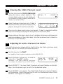
1
Adjusting the Minimum Winter Speed of Stage 1
This is the minimum speed of stage 1 fans when the outside temperature is
at or below winter's reference temperature (refer to the min. speed graphic
above). Winter's minimum speed is related to the regular minimum speed:
if the regular minimum speed changes, winter's minimum speed is adjusted
consequently. Refer to the MINIMUM VENTILATION chapter to set the
regular minimum speed of stage 1 fans.
Set the function to MIN. SPEED / CURVE using the menu select buttons.
Press on the down-arrow key in order to
select the "Min Speed Winter" display.
Accessible if the outside T° compensation on
the min. speed of stage 1 is enabled in the
USER SETUP.
Min Speed Winter
20%
Press on the MODIFY button then use the arrow keys to set the
minimum fan speed in winter the desired value. Press on the
MODIFY button once again to validate the new value.
This parameter can only be modified while the minimum speed curve is disabled.
2
Adjusting Winter's # of Degrees to Reach 100%
This is the number of degrees that are required to reach 100% of fans'
speed (fan stages 1-2) in winter (refer to the previous graphic). The
number of degrees to 100% in winter can be adjusted from 0.5 to 20 °F
(0.3°C to 11.1°C).
Set the function to STAGE 1 or STAGE 2 using the menu select buttons.
Press on the down-arrow key in order to
select "Degrees to 100% winter" display.
Accessible if the outside temperature compensation on the selected fan stage is enabled in
the USER SETUP.
Degrees to 100%
winter
4.0°F
Press on the MODIFY button then use the arrow keys to set the
number of degrees that are required to reach 100% of fan speed in
winter. Press on the MODIFY button to validate the new value.
44 EXPERT 2V4SA rev.01
EXPERT 2V4SA
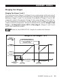
Merging Fan Stages
Merging Fan Stages 1 and 2
The transition from Stage 1 to Stage 2 can create jumps in the volume of
displaced air. This can be smoothed out by merging stages. When the merge
between stages 1 and 2 is activated, the speed of Stage 1 fans is decreased to match the speed of Stage 2 fans when Stage 2 fans start up.
As the temperature increases, the fan speed of both stages increases to
create a smooth progression. When the temperature reaches Stage 2 Start
Temp + #of degrees to reach 100% of fan stage 2, Stages 1 and 2 both
reach their maximum speed.
Refer to the USER SETUP chapter to enable this feature.
Merge of Fan Stages 1 & 2
WHEN STAGE 2 STARTS:
STAGE 1 FANS ARE DECREASED
AT STAGE 2’S MINIMUM SPEED
AND BOTH STAGES
INCREASES IN SPEED
STAGE 2
(MIN. SPEED)
STAGE 1
(MIN. SPEED)
0.3°F
STAGE 1
MINIMUM VENT.
CYCLE
# OF DEGREES
TO REACH 100%
OF STAGE 1
STAGE 1
START TEMP.
# OF DEGREES
TO REACH 100%
OF STAGE 2
ROOM T°
STAGE 2
START TEMP.
EXPERT 2V4SA rev.01
45
EXPERT 2V4SA
Merging Stages 2 and 3
The transition from Stage 2 to Stage 3 can create jumps in the volume of
displaced air. This can be smoothed out by merging two stages. When the
merge between stages 2 and 3 is activated, the speed of stage 2 fans is
decreased when stage 3 fans start up. As the temperature increases, the
speed of stage 2 fans is increased to create a smooth progression. When
the temperature reaches stage 3 start temp. + #of degrees to 100% of
stage 3, stages 2 fans reach their maximum speed once again and stage 3
fans operate at their full speed.
Merge of Fan Stages 2 & 3
VENTILATION
STAGE 3 ON
STAGE 3 OFF
STAGE 2 MIN.
VENTILATION TIMER
# OF DEGREES
TO 100% OF
STAGE 2
STAGE 1
START TEMP.
STAGE 2
START TEMP.
46 EXPERT 2V4SA rev.01
# OF DEGREES
TO 100% OF
STAGE 3
STAGE 3
STOP TEMP.
STAGE 3
START TEMP.
TEMPERATURE
EXPERT 2V4SA
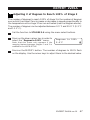
1
Adjusting # of Degrees to Reach 100% of Stage 3
The number of degrees to reach 100% of stage 3 is the number of degrees
over which the stage 2 fans increase or decrease in speed proportionally to
the temperature once stage 3 fans are activated (see the diagram above).
The number of degrees can be adjusted between 0.5°F and 20.0°F (0.3°C
and 11.1°C).
Set the function to STAGES 3-6 using the menu select buttons.
Press on the down-arrow key in order to
select the "Degrees to 100%" menu.
Note that this menu only appears if the
merging feature between stages 2 and 3 is
enabled in the USER SETUP.
Degrees to 100%
2.0°F
Press on the MODIFY button. The number of degrees to 100% flash
on the display. Use the arrow keys to adjust them to the desired value.
EXPERT 2V4SA rev.01
47
EXPERT 2V4SA
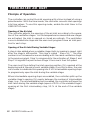
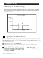
De-icing Stage 2 Fans
A de-icing cycle is provided to de-ice Stage 2 fans in cold weather conditions. If the controller uses an outside temperature sensor, de-icing cycles
are only activated when the outside temperature drops below a defined
temperature. If no outside temperature sensor is used, the de-icing cycle is
always active, no matter what the outside temperature is.
De-icing Cycles
ON
ON TIME
OFF
CYCLE TIME
Principle of Operation:
Step 1.
Stage 1 fans are stopped.
Step 2.
Stage 2 fans start running at full speed for 2 seconds then
return to their minimum speed during the On time.
Step 3.
Stage 2 fans are turned off.
Step 4.
Stage 1 fans' activity is resumed at the appropriate speed.
Step 5.
The cycle restarts after the cycle time has elapsed.
48 EXPERT 2V4SA rev.01
EXPERT 2V4SA
1
De-icing Start Temperature
The de-icing of stage 2 fans starts when the outside temperature drops
below this temperature. It can be adjusted from -40 to 120°F (-40.0 to
48.9°C). The start temperature can only be set if an outside temperature
sensor is used. If your controller doesn't have one, the de-icing cycles are
always active.
Set the function to STAGE 2 using the menu select buttons.
Press the down-arrow key to select the
outside temperature at which de-icing
cycles start.
De-icing out T°
41.0°F
Available if the de-icing feature and the outside temperature sensor are enabled in the USER SETUP.
Press MODIFY. The de-icing cycle's outside temperature flashes on
the display. Use the arrow keys to set the outside temperature below
which de-icing cycles start. Press MODIFY to validate the new value.
2
Adjusting De-icing Cycle Timer
The ON time can be adjusted from 0 to 900 seconds. The cycle time must
be greater than the ON time. It can be adjusted from 1 to 720 minutes.
Set the function to STAGE 2 using the menu select buttons.
Press the down-arrow key to select the
de-icing timer.
Available if the de-icing feature and the outside temperature sensor are enabled in the
USER SETUP.
On:
Cycle:
20sec
720min
Press on the MODIFY button. The On time flashes on the display. Use
the arrow keys to adjust it to the desired value.
Press on the MODIFY button once again. The cycle time flashes on
the display. Use the arrow keys and set the cycle time to the desired
value. Press MODIFY to validate the new value.
EXPERT 2V4SA rev.01
49
EXPERT 2V4SA
Mist Cooling
The last cooling stage can be configured as a mist stage. Mist units operate
according to two different timer cycles; the timer selection is based on the
room temperature (see graphic below).
Refer to the USER SETUP section to activate the mist stage and to see
which stage is used for this purpose (see the stages' definition table).
Mist Operation
MIST
STATUS
MIST UNITS
OPERATE
ACCORDING
TO TIMER 2
MIST UNITS
TURN ON
IN TIMER
MODE 1
MIST ON
(TIMER 2)
MIST UNITS
TURN OFF
MIST ON
(TIMER 1)
MIST
STOP
TEMP. 1
MIST
START
TEMP. 1
MIST
STOP
TEMP. 2
MIST
START
TEMP. 2
ROOM
TEMPERATURE
If humidity compensation is used, the mist units are disabled when the humidity reaches a user-defined maximum humidity level. Refer to the Humidity Compensation chapter for further information on this feature.
50 EXPERT 2V4SA rev.01
EXPERT 2V4SA
1
Setting Start and Stop Temperatures of Timers 1 & 2
Start and stop temperatures of both mist timers are directly related to the
set point. This means that when the main set point changes, the start and
stop temperatures are adjusted by the same amount.
The start temperature of the first mist timer can be adjusted from -40°F to
40°F (-22.2°C to 22.2°C) from the set point; the stop temperature can be
adjusted from 0.5°F to 40°F (0.3°C to 22.2°C) below its start temperature.
The start temperature of the second mist timer can be adjusted from 0.5°F
to 40°F (0.3°C to 22.2°C) above the start temperature of the first timer;
the stop temperature can be adjusted from 0.5 °F to 40°F (0.3°C to
22.2°C) below its start temperature.
Set the function to MIST using the menu
select buttons. The start temperature of
the first mist timer is displayed.
Mist Timer 1
StartT° 85.0°F
Accessible if mist units are enabled in the USER
SETUP.
Press on the MODIFY button. The start
temperature of the first timer flashes on
the display. Adjust the start temperature
to the proper value using the arrow keys.
Press on the down-arrow key. The stop
temperature for the first timer is
displayed.
StopT°
83.0°F
Press on the MODIFY button once again. The stop temperature flashes
on the display. Adjust it to the desired value using the arrow keys.
Press on the MODIFY button once again to validate.
Press on the down-arrow key twice. The start temperature of the
second mist timer is displayed.
Follow the same procedure as described above to set the start and
stop temperatures of the second mist timer.
EXPERT 2V4SA rev.01
51
EXPERT 2V4SA
2
Setting Timer 1 & 2 Time On and Time Off
The On and Off times of the mist units, of both timers, can be adjusted
from 0 to 60 minutes.
Set the function to MIST using the menu select buttons. The start
temperature of the first mist timer is displayed.
Accessible if mist units are enabled in the USER SETUP.
Press on the down-arrow key twice. The
On and Off times of the first mist timer
are displayed.
On:
Off:
1:00min
10:00min
Press on the MODIFY button. The on
time flashes on the display. Use the arrow keys to set it to the desired value.
Press on the MODIFY button. The off time flashes on the display. Use
the arrow keys to set it to the desired value. Press on the MODIFY
button to validate the value.
Press on the down-arrow key three times. The On and off times of the
second mist timer are displayed.
Press on the MODIFY button. The on time of the second mist timer
flashes on the display. Use the arrow keys to set it to the desired
value.
Press on the MODIFY button. The off time of the second mist timer
flashes on the display. Use the arrow keys to it to the desired value.
Press on the MODIFY button to validate the value.
52 EXPERT 2V4SA rev.01
EXPERT 2V4SA
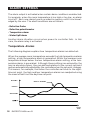
Relative Humidity (RH) Compensation
The controller has 2 ways to compensate for a high relative humidity (RH) level:
1. The minimum speed of stage 1 fans can be enhanced;
2. The mist units are shut off.
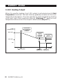
1. RH Compensation the Minimum Speed of Stage 1
The minimum speed of stage 1 fans can automatically be adjusted as a
function of relative humidity. As the humidity level increases, the minimum speed of stage 1 fans increases proportionally to compensate for the
change. At humidity levels at or below the humidity set point, stage 1
minimum speed is equal to the normal uncompensated speed. The user
specifies the percentage increase in minimum speed for a relative humidity
equal to the humidity set point + 10%. For example, if the minimum
speed is 40% and the compensation adjustment is 30%, the minimum
speed will be adjusted to 70% of full speed when the humidity rises 10%
above the humidity set point. In addition to adjusting the minimum speed,
the humidity compensation feature also changes the operation of the minimum ventilation cycle: if the controller is operating in minimum ventilation
mode when the relative humidity exceeds the humidity set point, the minimum ventilation fans are operated continuously rather than cycled.
STAGE 1
MINIMUM SPEED
RH Compensation on the
Minimum Speed of Stage 1 Fans
MIN. SPEED
COMP. (%)
COMPENSATED
SPEED
THE COMPENSATION
STARTS
NORMAL
MIN. SPEED
OFF
RELATIVE
HUMIDITY (RH)
RH SET POINT
EXPERT 2V4SA rev.01
53
EXPERT 2V4SA
2. RH Compensation on Mist Units
When the humidity level is too high, mist units are shut off to avoid
increasing the humidity level any further. They stop operating
whenever the humidity exceeds the Mist Shutoff value.
1
Viewing the Relative Humidity
Set the function to RELATIVE HUMIDITY using the menu select buttons.
The current humidity level is displayed.
Accessible if the humidity sensor is enabled in the USER SETUP.
Press on the down-arrow key once. The
minimum humidity reading for the
current day is displayed, along with the
time and date.
Press on the down-arrow key once again.
The maximum humidity reading for the
current day is displayed, along with the
time and date.
Keep pressing on the down-arrow key to
display the minimum and maximum humidity levels for the previous 6 days. Use
the up-arrow key to return to the previous display screens.
54 EXPERT 2V4SA rev.01
Humid.
50%
Humid. 01/01/03
Min 25% 12:00A
EXPERT 2V4SA
2
Adjusting Relative Humidity Set Point
The RH set point is the humidity level above which RH Compensation function start. This set point can be adjusted from 40 to 100% of humidity.
Set the function to STAGE 1 using the menu select buttons.
Press on the down-arrow key in order to
reach the "Humidity set point" display.
Accessible if the "RH Influence on Minimum
Speed" feature is enabled in the User Setup.
Humidity setp
65%
Press on the MODIFY button. The humidity set point flashes on the
display. Adjust the humidity set point to the desired value using the
arrow keys. Press on the MODIFY button to validate the new value.
3
Adjusting the Minimum Speed Compensation
This is the increment in the minimum speed of fan stage 1 for humidity
levels that are higher than the humidity set point + 10% (refer to the
previous graphic). The value ranges from 0 to 100%.
Set the function to STAGE 1 using the menu select buttons.
Press on the down-arrow key in order to
display the minimum speed compensation menu.
RH speed comp.
60%
Note that this menu only appears if the "RH
Influence on Minimum Speed" feature has been
activated in the User Setup.
Press on the MODIFY button. The minimum speed compensation flashes
on the display. Use the arrow keys to set the speed compensation to
the desired value. Press MODIFY to validate the new value.
EXPERT 2V4SA rev.01
55
EXPERT 2V4SA
4
Adjusting the Mist Shutoff Set Point
This mist shutoff set point is the humidity level above which mist units are
deactivated. It can be adjusted from 40% to 99% of humidity. Select
"Off" to deactivate this function.
Set the function to MIST using the menu select buttons.
Available if mist units are enabled in the USER SETUP.
Press on the down-arrow in order to
select the "Mist Shutoff at" display.
Press on the MODIFY button. The mist
shutoff set point flashes on the display.
Use the arrow keys to adjust the set
point to the desired value. Press
MODIFY to validate the new value.
56 EXPERT 2V4SA rev.01
Mist Shutoff at
95%
HEATER SETTINGS
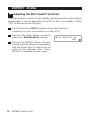
Regular Heating Stages
Stages 5 and 6 can be used to control heating units. The controller
automatically uses stage 6 as the heater stage if only 1 heating stage is
activated (refer to the stage option table in the USER SETUP). Regular
heating stages operate according to the average room temperature, using
start and stop temperatures.
Regular Heating Stages
HEATERS
HEATER 1 + 2
ARE ACTIVATED
HEATERS 1-2 ON
HEATER 1 IS
ACTIVATED
HEATER 1 ON
HEATER 2 OFF
HEATER 2
START TEMP.
HEATER 2
STOP TEMP.
HEATER 1
START TEMP.
HEATER 1
STOP TEMP.
SET
POINT
ROOM
TEMP.
EXPERT 2V4SA rev.01
57
EXPERT 2V4SA
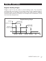
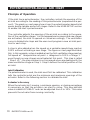
Zoned Heating Stages
If zoned heater stages are used, both heater outputs do not operate
according to the same temperature probes. The user determines which of
the temperature probes is assigned to each heating stage. By default,
sensors 1 and 2 are assigned to the first heater stage and temperature
sensors 3 and 4 are assigned to the second heater stage. The controller
then uses the average temperature of selected sensors to operate the
heater stages.
Activate the "Use zoned heaters" option in the USER SETUP to
activate this function.
Zoned Heaters
HEATING
HEATER
TURNS ON
HEATER
TURNS OFF
HEATER ON
HEATER OFF
HEATER 1 OR 2
START TEMP.
58 EXPERT 2V4SA rev.01
HEATER 1 OR 2
STOP TEMP.
SET
POINT
ROOM
TEMP.
EXPERT 2V4SA
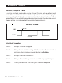
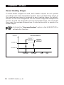
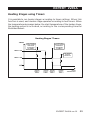
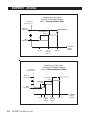
Heating Stages using Timers
It is possible to run heater stages according to timer settings. When this
function is used, each heater stage operates according to two timers. When
the temperature decreases below the start temperature of the heater stage,
the heating output is activated, according to the corresponding timer as
illustrated below:
Heating Stages’ Timers
TIMERS
THE HEATING
OUTPUT STARTS
OPERATING
ACCORDING
TO TIMER 2
THE HEATING
OUTPUT STARTS
OPERATING
ACCORDING
TO TIMER 1
TIMER 2 ON
THE HEATING
OUTPUT
TURNS OFF
TIMER 1 ON
HEATER
START T°
TIMER 2
HEATER
STOP T°
TIMER 2
HEATER
START T°
TIMER 1
HEATER
STOP T°
TIMER 1
ROOM
TEMPERATURE
EXPERT 2V4SA rev.01
59
EXPERT 2V4SA
1
Adjusting the Start T° of Heater Stages 1 - 2
The start temperature of a heating stage can be adjusted from 40°F
(22.2°C) below the set point to 39.5°F (21.9°C) above the set point; its
stop temperature can be adjusted from O.5°F above the start temperature
to 40°F (22.2°C) above the set point. Using a start temperature that is
greater than the set point can be used to control heat mats for instance.
Set the function to HEATERS using the
menu select buttons. The start temperature of heater 1 is displayed.
Heater 1
StartT° 73.0°F
Available if a heater is enabled in the USER
SETUP.
Press on the MODIFY button. The start temperature of the first heater
stage 1 flashes on the display. Use the arrow keys to set it to the
desired value. Press on the MODIFY button to validate.
Press on the down-arrow key. The stop
temperature of the first heater stage is
displayed.
StopT°
75.0°F
Press on the MODIFY button once again. The stop temperature flashes
on the display. Set it to the desired value using the arrow keys. Press
on the MODIFY button to validate.
If two heaters are used, press on the down-arrow key, in order to
display the start temperature of the second heater stage then follow
the same procedure to adjust the start and stop temperatures of the
second heater stage (if applicable).
2
Adjusting Heater Stages' Timer
If the timer has been enabled in the USER SETUP, follow this procedure to
adjust the timer's On and Off times. They can be adjusted from 0 to 15 minutes, in increments of 15 seconds.
Set the function to HEATERS using the
menu select buttons. The start temperature of heater 1 is displayed.
Available if a heater is enabled in the USER
SETUP.
60 EXPERT 2V4SA rev.01
Heat 1 Timer 1
StartT° 73.0°F
EXPERT 2V4SA
Press on the MODIFY button. The start temperature for the first timer
of the first heater stage flashes on the display. Use the arrow keys to
set it to the desired value. Press on the MODIFY button to validate.
Press on the down-arrow key once. The stop temperature for the first
timer of the first heater stage flashes on the display. Use the arrow
keys to set it to the desired value. Press on the MODIFY button to
validate.
Press on the down-arrow key once again.
The On and Off times for the first timer
of the first heating stage are displayed.
On:
Off:
1:00min
1:00min
Note that this menu is only accessible if the
timer has been enabled on heating stages in the USER SETUP.
Press on the MODIFY button. The On time of the first timer flashes on
the display. Use the arrow keys to set it to the desired value.
Press on the MODIFY button once again. The Off time of the first timer
flashes on the display. Use the arrow keys to set it to the desired value.
Press on the down-arrow key once again.
The start temperature for the second timer
of the first heating stage is displayed.
Heat 1 Timer 2
StartT° 71.0°F
Follow the same procedure to set the start/stop temperatures and the
On and Off times for the second timer of the first heater stage.
If two heater stages are used, proceed in similar fashion to the timers
of the second heating stage (if applicable).
EXPERT 2V4SA rev.01
61
TIMER-BASED AIR INLET
Principle of Operation
The controller can control the inlet opening with a timer instead of using a
potentiometer. With the timer mode, the controller converts inlet openings
into time values. To use this opening mode, enable the inlet timer in the
USER SETUP menu.
Opening of the Air Inlet
The controller adjusts the opening of the air inlet according to the operation of the ventilation stages. As the temperature increases and new stages
are activated, the inlet is opened or closed accordingly. The ventilation
curve is divided into steps and the user must program a new air inlet position for each step.
Opening of the Air Inlet During Variable Stages
A step is also added when a variable stage starts increasing in speed, right
after the stage's differential. This step is called “ Step x Hi ”. The step
number is not increased as we are dealing with the same ventilation stage.
In the previous graph, Step 1 corresponds to the activation of Stage 1 and
Step 1 Hi signals the point where Stage 1 fans reach their full speed.
The user must thus define the inlet opening position (%) required at the
beginning and at the end of each variable stage. Once this is done, the user
can choose to subdivide this opening into 0 to 2 intermediate opening steps
to progressively open the inlet during the variable stage.
When intermediate opening steps are enabled, the controller splits up the
variable stage's opening (%) evenly between the number of intermediate
steps (e.g., if one intermediate step is enabled, the controller will open the
inlet twice during the variable stage (opens of 50% of the variable stage's
opening at the first intermediary step, 50 % at the end of the variable
stage).
62 EXPERT 2V4SA rev.01
EXPERT 2V4SA
Intermediate steps are activated when a variable stage reaches predefined
fan speeds. These fan speeds are set differently depending on the number
of intermediate steps in use. For example, if 1 intermediate step is enabled, the inlet opens during half the variable stage's opening when the
stage's speed is of 75 %; it reaches the stage's HI opening position when
the fan speed is 100 % (refer to the following graphs).
The three following graphs illustrate when each intermediate step starts.
Opening of the Inlet
During a Variable Stage
with 0 Intermediate Step
Opening
(Time or %)
Step HI
Opening
Step
Opening
50 %
100 %
Variable
Stage
Speed
EXPERT 2V4SA rev.01
63
EXPERT 2V4SA
Opening
(Time or %)
Opening of the Inlet
During a Variable Stage
with 1 Intermediate Step
Step HI
Opening
Intermediary
Step 1
1/2
1/2
Step
Opening
50 %
Opening
(Time or %)
75 %
(interm.
step 1)
Opening of the Inlet
During a Variable Stage
with 2 Intermediate Steps
Step HI
Opening
Intermediary
Step 2
1/3
1/3
Step
Opening
100 %
Variable
Stage
Speed
Intermediary
Step 1
1/3
50 %
64 EXPERT 2V4SA rev.01
60 %
85 %
(interm. (interm.
step1)
step2
100 %
Variable
Stage
Speed
EXPERT 2V4SA
Opening
(%)
STEP 6
STEP 5
STEP 4
STEP 3 HI
STEP 3
STEP 2 HI
STEP 2
STEP 1 HI
STEP 1
STEP 0
MINIMUM
VENTILATION
STEP 1
# OF DEGREES
TO REACH 100%
OF STAGE 1
SET POINT
STEP 1 HI
STEP 3
# OF DEGREES
TO REACH 100%
OF STAGE 3
STAGE 3
START T°
STAGE 3
STOP T°
STEP 2 HI
STEP 4
STAGE 4
START T°
STAGE 4
STOP T°
STEP 6
STAGE 6
START T°
STAGE 6
STOP T°
STEP 5
STAGE 5
START T°
STAGE 5
STOP T°
* STEP 3 HI IS ONLY
USED IF THE MERGE
BETWEEN STAGE 2
AND STAGE 3 IS ACTIVATED.
STEP 3 HI
Opening of the Timer-Based Air Inlet
STEP 2
# OF DEGREES
TO REACH 100%
OF STAGE 2
STAGE 2
START T°
Room T°
65
EXPERT 2V4SA rev.01
EXPERT 2V4SA
Automatic Reset of the Actuator's Position
The controller needs to reset the actuator’s position at regular interval to
make sure the inlet’s position is always accurate. Resetting the actuator’s
position clears all accumulated time offsets caused by the frequent openings and closings of the inlet. This reset is performed automatically according to one of these two methods:
•
Reset the minimum position only (Close mode)
Each time a reset is performed, the inlet totally closes. Once the
actuator’s position is reset, the inlet returns to its previous position.
•
Reset toward the nearest position (Open/Close mode)
Each time a reset is performed, the inlet fully opens on condition that
its current opening is over 50 %; if the current inlet opening is less
than 50 %, the controller closes the inlet to reset the actuator’s position. This way, the inlet never closes when the room temperature already asks for a large opening.
Make sure limit switches are located at both ends of
the actuator when using this resetting method.
Maximum Opening of the Timer-Based Inlet
A supplementary stage can be calibrated in order to continue opening the
air inlet beyond the last temperature of the controller's ventilation stages.
This supplementary stage is used to direct the airflow more efficiently
during periods of warm
weather. The user must
Maximum Opening Stage
specify the maximum inof the Timer-Based Inlet
INLET
let opening and the numOPENING
ber of degrees over the
MAX.
last ventilation stage at
OPENING
which this opening must
INLET
be reached.
OPENING OF
THE LAST
STAGE
MIN.
OPENING
CONTROLLER
STAGES
SET POINT
66 EXPERT 2V4SA rev.01
# OF
DEGREES
TO MAX. OPENING
ROOM T°
EXPERT 2V4SA
Settings
1
Adjusting the Reference Points (Steps)
The controller adjusts the opening of the air inlet according to the operation of the ventilation stages. The following procedure shows how to assign an inlet position to each ventilation stage.
Set the function to INLET to adjust the reference points of the air inlet
Accessible if the air inlet is enabled in the USER SETUP.
Press the down-arrow key once. The
opening of step 0 is displayed.
St. 0
10%
Press MODIFY. The opening of step 0 flashes on the display. Use the
arrow keys to set it to the desired value. Press MODIFY once again to
validate.
Press the down-arrow key. The opening of step 1 and step 1 Hi are
displayed. Press MODIFY then use the arrow keys to adjust these openings to the desired value. Proceed in similar fashion to assign an inlet
opening to every step.
2
Setting the Total Run Time of the Inlet
Enter the exact time that is required to reach the actuator's maximum
limit switch when the actuator is closed. The controller refers to this value
to convert opening values into time values.
Set the function to INLET.
Accessible if the air inlet is enabled in the USER SETUP.
Press the down-arrow keyto select the
"Total Run Time" display.
Accessible if the timer-based inlet option is
enabled in the USER SETUP.
Total Run Time
2:00min
Press MODIFY then use the arrow keys to adjust the total run time to
the desired value.
EXPERT 2V4SA rev.01
67
EXPERT 2V4SA
3
Setting the Maximum Opening
The maximum inlet opening is reached beyond the last ventilation stage.
Set the function to INLET.
Accessible if the air inlet is enabled in the
USER SETUP.
Press the down-arrow key, in order to
select "Max Opening" display.
Max opening
100%
Press MODIFY then use the arrow keys
to adjust the max opening to the desired value. Press MODIFY to validate.
4
Setting the # of Degrees to Maximum Opening
This is the temperature interval over which the air inlet goes from the
opening associated with the last ventilation stage towards its maximum
opening (see previous graphs). This parameter can be adjusted from 0.5 to
20°F (0.3 to 11.1°C).
Set the function to INLET.
Accessible if the air inlet is enabled in the
USER SETUP.
Press the down-arrow key, to select the
"Degrees to max opening" display.
Press MODIFY. The number of degrees
to max opening flash on the display. Use
the arrow keys to set this parameter
to the desired value.
68 EXPERT 2V4SA rev.01
Degrees to max
opening
5.0°F
EXPERT 2V4SA
5
Selecting the Reset Mode
This section explains how to choose the desired resetting method:
choose “Open/Close” to reset the actuator toward its nearest position;
select “Close” to reset the actuator toward its closed position only;
select “Off” to disable the auto-reset function. Refer to the previous
section for further information about this feature.
Set the function to INLET.
Accessible if the air inlet is enabled in the USER SETUP.
Press the down-arrow key to select the
"Reset Mode" display.
Accessible if the timer-based inlet option is
enabled in the USER SETUP.
Reset Mode
Open/Close
Press MODIFY then use the arrow keys
to select the desired reset mode then
press MODIFY to validate.
6
Auto-Reset Time & Frequency
This section shows how to set the time at which the reset is performed
and the frequency at which it occurs. The reset can be performed once
every 1-7 days.
Set the function to INLET.
Accessible if the air inlet is enabled in the USER SETUP.
Press the down-arrow key to select the
"Reset Time" display.
Accessible if the timer-based inlet option is
enabled in the USER SETUP.
Reset Time
6:00A
Press MODIFY then use the arrow keys
to select the time at which reset needs
to be performed then press MODIFY to
validate.
EXPERT 2V4SA rev.01
69
EXPERT 2V4SA
Press the down-arrow key once more.
The frequency at which the actuator
needs to be reset is displayed.
Reset Period
3days
Press MODIFY then use the arrow keys
to select the frequency (Period) then
press MODIFY twice to validate.
7
Performing a Manual Reset
It is possible to reset the actuator's position without waiting for the next
time of reset. The following procedure shows how to perform a manual
reset.
Set the function to INLET.
Accessible if the air inlet is enabled in the USER SETUP.
Press the down-arrow key to select the
"Reset Now?" display.
Accessible if the timer-based inlet option is
enabled in the USER SETUP.
Press MODIFY twice then press the
up-arrow key to start the actuator's
reset then press MODIFY to validate.
The controller launches the reset and
the "Yes" answer on screen switches
back to "No".
70 EXPERT 2V4SA rev.01
Reset Now?
No
EXPERT 2V4SA
Manual Opening of the Air Inlet
It is possible to open (or close) the air inlet manually. When an inlet is
controlled manually, the controller stops controlling the inlet output.
Set the function to INLET. The current
position of the inlet and its operating
mode are displayed (Auto/ Open/ Off/
Close).
Opening
Mode
35%
Open
Accessible if the air inlet is enabled in the
USER SETUP.
Press MODIFY then use the arrow keys to select the proper control
mode: select "Open" to manually open the inlet; select "Close" to manually close it; select "Off" to stop the actuator.
Do not forget to return to the automatic control mode afterwards so
that the controller can take back control of this output.
:$51,1*
If the inlet is controlled by a timer, perform a
manual reset of the actuator's position after
each manual opening of the air inlet.
EXPERT 2V4SA rev.01
71
POTENTIOMETER-BASED AIR INLET
Principle of Operation
If the inlet has a potentiometer, the controller controls the opening of the
air inlet according to the reading of this potentiometer (expressed as a percent). The graph on next page shows how the potentiometer-based inlet
opens during variable and on-off stages. Refer to the USER SETUP section
to enable the inlet's potentiometer.
The controller adjusts the opening of the air inlet according to the operation of the ventilation stages. As the temperature increases and new stages
are activated, the inlet is opened or closed accordingly. The ventilation
curve is divided into steps and the user must program a new air inlet position for each step.
A step is also added when the speed on a variable speed stage reaches
100% without activating a new stage. The figure on next page illustrates
this. In this example, a step is added when the first ventilation stage reaches
full speed at “ temperature set point + #degrees to 100% of stage 1 ”
even though no new stages are activated at this point. This step is called
“ Step 1 Hi ”; the step number is not increased as we are dealing with the
same ventilation stage as Step 1. Step 0 defines the initial position of the
air inlet.
Inlet Calibration
If a potentiometer is used, the inlet must first be calibrated. This calibration
tells the controller what are the minimum and maximum openings of the
actuator. Refer to the following section to calibrate the inlet.
Actuator's Accuracy
When the actuator isn't moving, a minimum opening or closing percentage
is necessary so that the actuator can start to move. This user-defined
value is called ACCURACY and can be adjusted from 2 to 10%. This value
prevents the actuator from moving constantly.
72 EXPERT 2V4SA rev.01
STEP 0
STEP 1
STEP 1 HI
STEP 2
STEP 2 HI
STEP 3
STEP 3 HI
STEP 4
STEP 5
STEP 6
Opening (%)
MINIMUM
VENTILATION
SET POINT
# OF DEGREES
TO REACH 100%
OF STAGE 1
STEP 1
STEP 1 HI
STAGE 2
START T°
# OF DEGREES
TO REACH 100%
OF STAGE 2
STEP 2
# OF DEGREES
TO REACH 100%
OF STAGE 3
STEP 3
STAGE 3
START T°
STAGE 3
STOP T°
STEP 2 HI
STAGE 4
START T°
STAGE 4
STOP T°
STEP 6
STAGE 6
START T°
STAGE 6
STOP T°
STEP 5
STAGE 5
START T°
STAGE 5
STOP T°
3 HI IS ONLY
USED IF THE MERGE
BETWEEN STAGE 2
AND STAGE 3 IS ACTIVATED.
* STEP
STEP 3 HI
STEP 4
Opening of the Potentiometer-Based Air Inlet
Room T°
EXPERT 2V4SA
EXPERT 2V4SA rev.01
73
EXPERT 2V4SA
Maximum Opening of the Air Inlet
A supplementary stage can be calibrated in order to continue opening the
air inlet beyond the last temperature of the controller's ventilation stages.
This supplementary stage is used to direct the airflow more efficiently
during periods of warm weather. The user must specify the maximum inlet
opening and the number of degrees over the last ventilation stage at which
this opening must be reached. The inlet can reach this maximum opening
two different ways:
1) Progressive Mode:
The controller gradually opens or
closes the panels in a linear
fashion as the room temperature
rises above the last reference
point temperature. The inlet
reaches its maximum opening at
the "temperature of the last
reference point + #of degrees
to max. opening".
2) Dump Mode:
When the temperature increases
above the last ventilation stage,
the air inlet position is maintained. When the temperature
reaches "temperature of the last
reference point + #of degrees
to max. opening", the inlet opens
to its maximum opening at once.
MAXIMUM OPENING STAGE:
PROGRESSIVE MODE
INLET
OPENING
MAX.
OPENING
INLET
OPENING
IN LAST
STAGE
MIN.
OPENING
CONTROLLER
STAGES
SET POINT
INLET
OPENING
ROOM T°
MAXIMUM OPENING STAGE:
DUMPING MODE
MAX.
OPENING
INLET
OPENING
IN LAST
STAGE
MIN.
OPENING
CONTROLLER
STAGES
SET POINT
74 EXPERT 2V4SA rev.01
# OF
DEGREES
TO MAX.
OPENING
# OF
DEGREES
TO MAX.
OPENING
ROOM T°
EXPERT 2V4SA
Settings
1
Inlet Calibration
The calibration tells the controller what are the minimum and maximum
openings of the actuator. The controllers automatically calibrates the minimum position according to the limit switch. The user must then open the
actuator to its maximum position using the manual opening function.
Set the function to INLET .
Accessible if the inlet is enabled in the USER SETUP.
Press the down-arrow key in order to
select the "Calib Inlet?" display.
Calib Inlet?
Accessible if the inlet's potentiometer is enabled in the USER SETUP.
Yes
Press MODIFY then press the up-arrow key to select "Yes". Press
MODIFY once again to validate. The calibration starts: the actuator
automatically closes to its minimum position, as determined by the
limit switch). The message "Please wait while closing" is displayed.
Once the inlet's minimum position (0%)
OpenToMax
Open
is defined, the controller asks to open
Save
calib
No
the air inlet to its maximum position.
Select the "Open" or "Close" functions
to set the actuator to its maximum position (100%). When it is properly positioned press the up or down-arrow key to select "Off", then
press MODIFY to stop the actuator.
Once the max position (100%) is defined, select "Yes" to save the calibration then press MODIFY to validate.
The calibration is now done and the inlet starts being controlled automatically
by the controller. The controller also displays the message "Calibration completed !".
OpenToMax
Save calib
Open
Yes
Calibration
completed !
EXPERT 2V4SA rev.01
75
EXPERT 2V4SA
2
Adjusting the Reference Points (Steps)
The controller adjusts the opening of the air inlet according to the operation of the ventilation stages. The following procedure shows how to assign an inlet position to each ventilation stage.
Set the function to INLET to adjust the reference points of the air inlet
Accessible if the air inlet is enabled in the USER SETUP.
Press the down-arrow key once. The
opening of step 0 is displayed.
St. 0
10%
Press MODIFY. The opening of step 0
flashes on the display. Use the arrow
keys to set it to the desired value. Press
MODIFY once again to validate.
Press the down-arrow key. The opening of step 1 and step 1 Hi are
displayed. Press MODIFY then use the arrow keys to adjust these
openings to the desired value. Proceed in similar fashion to assign an
inlet opening to every step.
3
Setting the Maximum Opening
The maximum inlet opening is reached beyond the last ventilation stage.
Set the function to INLET.
Accessible if the air inlet is enabled in the USER SETUP.
Press the down-arrow key, in order to
select "Max Opening" display.
Press MODIFY then use the arrow
keys to adjust the max opening to the
desired value. Press MODIFY to validate.
76 EXPERT 2V4SA rev.01
Max opening
100%
EXPERT 2V4SA
4
Setting the # of Degrees to Maximum Opening
This is the temperature interval over which the air inlet goes from the
opening associated with the last ventilation stage towards its maximum
opening (see previous graphs). This parameter can be adjusted from 0.5 to
20°F (0.3 to 11.1°C).
Set the function to INLET.
Accessible if the air inlet is enabled in the USER
SETUP.
Press the down-arrow key, to select the
"Degrees to max opening" display.
Degrees to max
opening
5.0°F
Press MODIFY. The number of degrees
to max opening flash on the display. Use
the arrow keys to set this parameter to
the desired value.
5
Selecting the Maximum Opening Mode
Select the proper maximum opening method: dumping / progressive. Refer
to previous graphs.
Set the function to INLET.
Accessible if the air inlet is enabled in the
USER SETUP.
Press the down-arrow key, in order to
select "Max.Opening Mode" display.
Max Opening Mode
Progressive
Accessible if the inlet's potentiometer is enabled in the USER SETUP.
Press MODIFY then use the arrow keys
to select the proper opening mode
(dumping / progressive). Press MODIFY
once again to validate.
EXPERT 2V4SA rev.01
77
EXPERT 2V4SA
6
Adjusting the Accuracy of the Air Inlet
When the actuator isn't moving, a minimum opening or closing percentage
is required so that the actuator can start to move. This value, called
accuracy, can be adjusted from 2 to 10%. The accuracy parameter prevents the actuator from flickering.
Set the function to INLET.
Accessible if the air inlet is enabled in the
USER SETUP.
Press the down-arrow key to select the
"Accuracy" display.
Accuracy
+/-
3%
Press MODIFY then use the arrow keys to adjust it to the desired
value.
78 EXPERT 2V4SA rev.01
EXPERT 2V4SA
Manual Opening of the Air Inlet
It is possible to open (or close) the air inlet manually. When an inlet is
controlled manually, the controller stops controlling this inlet output and
stops monitoring potentiometer alarms.
Set the function to INLET. The current
position of the inlet and its operating
mode are displayed (Auto/ Open/ Off/
Close).
Opening
Mode
35%
Open
Accessible if the air inlet is enabled in the
USER SETUP.
Press MODIFY then use the arrow keys to select the proper mode.
Select "Open" to manually open the inlet. Select "Close" to manually
close it or select "Off" to stop the actuator.
Do not forget to return to the automatic control mode afterwards so
that the controller can take back control of this output.
EXPERT 2V4SA rev.01
79
EXPERT 2V4SA
Static Pressure Compensation on the Inlet Opening
A compensation can be used to ensure a certain uniformity in the static pressure level in the room. This static pressure compensation allows opening or
closing the air inlet further when the static pressure level is out of range.
When the static pressure level exceeds the normal range (above the Hi
Pressure Set point or below the Lo Pressure Set Point), the controller
waits for the Compensation Delay to make sure this unusual pressure condition is not temporary. If the pressure is still out of range after this delay
has elapsed, the inlet compensation (%) is applied on the opening of the
inlet: it closes further by its compensation value (%) when the pressure
level is too low [point A on the graphic] or opens further by its compensation value (%) when the pressure level is too high [point C on the graphic].
The controller then waits for the Compensation Delay once again. If the
pressure level is still out of range afterwards, the opening compensation is
applied once more. This cycle is repeated up until the pressure gets back
to the normal range or until a new stage starts. When the pressure level
gets back to the normal range [points B & D on the graphic], the inlet
keeps its compensated position until the beginning of a new stage. No
compensation is applied on the inlet opening when a new stage starts.
Static Pressure Compensation
on the Inlet Opening
INCREASE
INLET OPENING
STATIC
PRESSURE
KEEP
INLET POSITION
C
HIGH
SET POINT*
D
B
A
REDUCE
INLET OPENING
LOW
SET POINT*
Comp.
Delay
Comp.
Delay
Comp.
Delay
The inlet The inlet The inlet
closes further
closes
closes
[by its comp. further further
value (%)]
80 EXPERT 2V4SA rev.01
Comp.
Delay
The inlet
opens further
[by its comp.
value (%)]
Comp.
Delay
Comp.
Delay
The inlet
opens
further
The inlet
opens
further
TIME
EXPERT 2V4SA
1
Viewing the Static Pressure Level
Set the function to STATIC PRESSURE
using the menu select buttons. The
current static pressure level is displayed.
Stat. P
.05"WC
Accessible if the static pressure sensor is enabled in the USER SETUP.
Press the down-arrow key once. Today's
minimum static pressure reading is displayed, along with the time and date.
Stat P 31/12/XX
Min .02 12:00A
Press on the down-arrow key once again. Today's maximum static
pressure reading is displayed, along with the time and date.
Keep pressing the down-arrow key to display minimum and maximum
pressure readings of the 6 last days. Use the up-arrow key to return to
previous screen displays.
2
Adjusting Hi and Lo Pressure Set Points
The static pressure compensation starts when the static pressure level
exceeds the Hi or Lo static pressure set points.
Set the function to INLET.
Accessible if the air inlet is enabled in the USER SETUP.
Press the down-arrow key, in order to
select the " Low SP" display.
Available if the static pressure compensation feature is enabled in the USER SETUP.
Low SP
High SP
.00"WC
.10"WC
Press MODIFY. The Low Static Pressure set point flashes on the display. Use the arrow keys to set it to the desired value.
Press MODIFY once again. The High Static Pressure set point flashes
on the display. Use the arrow keys to set it to the desired value. Press
MODIFY once again to validate.
EXPERT 2V4SA rev.01
81
EXPERT 2V4SA
3
Adjusting the Compensation Value
Select the opening percentage that must be added or removed when a
compensation is applied on the inlet openings. Adjustable from 0 to 10%
Set the function to INLET.
Accessible if the air inlet is enabled in the USER SETUP.
Press the down-arrow key in order to
select the "Stat. P compens." display.
Available if the static pressure compensation
feature is enabled in the USER SETUP.
Stat. P compens
5%
Press MODIFY. The compensation value
flashes on the display. Use the arrow
keys to set it to the desired value.
4
Adjusting the Compensation Delay
Each time the compensation delay elapses and the pressure level exceeds
the normal range, a compensation is applied on the inlet opening. This delay
can be adjusted from 15 to 900 seconds.
Set the function to INLET.
Accessible if the air inlet is enabled in the USER SETUP.
Press the down-arrow key in order to
select "Compens. delay." display.
Available if the static pressure compensation
feature is enabled in the USER SETUP.
Press MODIFY. The compensation delay flashes on the display. Use the arrow keys to set it to the proper value.
Press MODIFY once again to validate.
82 EXPERT 2V4SA rev.01
Compens.delay
30 sec
0-10V OUTPUTS
The EXPERT 2V4SA has one 0-10V output that can be used in many different ways. This output can either be used as a supplementary fan or heating
stage, it can also be used to control heat mats or chimney dampers. The
following section explains each of these features separately. Refer to the
USER SETUP to enable the 0-10V output and to select its function.
Note that the controller may give a 10-0V signal instead of a 0-10V signal.
This may be useful for safety reasons: if the main controller loses power
and its 0-10V output drops to 0V, the controller then gives the
maximum load to the module connected on the output.
EXPERT 2V4SA rev.01
83
EXPERT 2V4SA
0-10V Ventilation Output
The controller has one 0-10V output that can be used to control a supplementary ventilation stage. Refer to the USER SETUP section to enable this
type of output.
0-10V OUTPUT : VENTILATION MODE
0-10V OUTPUT
FANS
THE 0-10V OUTPUT
OPERATES
CONTINUOUSLY
AND STARTS
INCREASING IN SPEED
MAXIMUM
SPEED
THE 0-10V OUTPUT
REACHES
ITS MAX. SPEED
THE 0-10V OUTPUT
IS DEACTIVATED
THE 0-10V OUTPUT
OPERATES ACCORDING
TO THE TIMER SETTINGS
MINIMUM
SPEED
MAX T°
STOP AT
ROOM
TEMP.
START
TEMPERATURE
WHEN THE ROOM TEMPERATURE INCREASES:
Below the start T° :
The output operates at its minimum speed, according to a timer;
At the start T°:
The 0-10V fan output runs continuously at its minimum speed and starts
increasing in speed as the temperature increases;
At the Maximum T°:
The 0-10V fan output reaches its maximum speed;
Above the "Stop At" temperature:
The 0-10V fan output is disabled.
84 EXPERT 2V4SA rev.01
EXPERT 2V4SA
1
Adjusting the Start Temperature of 0-10V Fan Outputs
The 0-10V fan output start running when the room temperature reaches
the output's start temperature. This temperature can be set as an absolute
value or it can be related to the set point. This means that when the set
point changes, the start temperature is adjusted by the same amount. This
function must be set in the USER SETUP ("0-10V follows set point"). The
start temperature can be set from -40 to 120°F (-40 to 48.9°C).
Set the function to 0-10V OUTPUT. The
start temperature of the selected output
is displayed.
StartT° 75.0°F
Make sure the 0-10V output uses the "Ventilation" option in the USER SETUP.
Press MODIFY. The start temperature flashes on the display. Use the
arrow keys to set it to the desired value then press MODIFY again to
validate.
2
Adjusting Min/Max. Speeds of the 0-10V Fan Output
The minimum and maximum speed of the 0-10V fans can be adjusted from
0 to 100%.
Set the function to 0-10V OUTPUT.
Make sure the 0-10V output uses the "Ventilation" option in the USER SETUP.
Press the down-arrow key in order to select the Min/Max speed display.
Min Spd
Max Spd
40%
100%
Press MODIFY. The minimum speed
flashes on the display. Use the arrow
keys to set it to the desired value.
Press MODIFY once again, the maximum
speed flashes on the display. Use the arrow keys to set it to the desired value.
EXPERT 2V4SA rev.01
85
EXPERT 2V4SA
3
Operating Temperatures of the 0-10V Fan Output
The maximum temperature is the temperature at which the 0-10V fan
output reaches its full speed. It can be adjusted from 0.5 to 20°F (0.3°C
to 11.1°C) above the output's start temperature.
The stop temperature is the temperature above which the output is deactivated as the temperature rises (refer to the previous diagram). It can be
set from 0.1°F (0.1°C) above the output's start temperature to 120°F
(48.9°C). Select "Off" if you do not wish to deactivate the output.
Set the function to 0-10V OUTPUT.
Make sure the 0-10V output uses the "Ventilation" option in the USER SETUP.
Press the down-arrow key in order to select the "MaxT° / Stop at" display.
Max T° 77.0°F
Stop at 79.0°F
Press on the MODIFY button. The maximum temperature flashes on the display.
Use the arrow keys to set it to the desired value.
Press on the MODIFY button once again,
the stop temperature flashes on the display. Use the arrow keys to set it to the
desired value.
4
Setting the 0-10V Fan Outputs' Timer
When the temperature falls below the start temperature of the
0-10V fan output, 0-10V fans operate at their minimum speed, according
to a timer. The timer's On and Off times can be adjusted from 0 to 900 seconds, in increments of 15 seconds.
Set the function to 0-10V OUTPUT.
Make sure the 0-10V output uses the "Ventilation" option in the USER SETUP.
86 EXPERT 2V4SA rev.01
EXPERT 2V4SA
Press on the down-arrow key and select
the timer display.
On:
Off
15sec
0sec
Press on the MODIFY button. The On
time flashes on the display. Use the arrow keys to set it to the desired value.
Press on the MODIFY button once again, the Off time flashes on the
display. Use the arrow keys to set it to the desired value.
5
Assigning T° Probes to 0-10V Fan Outputs
When used as a ventilation output, the 0-10V output operates according to
the average temperature of chosen temperature probes. The following procedure shows how to assign temperature sensors to the 0-10V fan output.
Set the function to 0-10V OUTPUT.
Make sure the 0-10V output uses the "Ventilation" option in the USER SETUP.
Press on the down-arrow key to select
the probe selection display.
Probes
1234
Select which of the sensors are used to control the selected 0-10V
output. Blinking digits represent probes that are assigned for this purpose. At least one temperature probe must be selected. Press on the
MODIFY button then set each probe's status by using the arrow keys.
EXPERT 2V4SA rev.01
87
EXPERT 2V4SA
0-10V Heating Output
When it is used for heating, the 0-10V output is activated when its Start
Temperature is reached. The heat intensity gradually increases as the room
temperature decreases. The user specifies at what temperature heating
units must reach their maximum intensity (Maximum T°) and the room
temperature above which the output is deactivated (Stop at T°).
0-10V
OUTPUT (%)
THE HEATING
DEVICE REACHES
ITS MAXIMUM
INTENSITY
MAX. HEAT
THE HEATING
DEVICE
TURNS ON
AT ITS MIN.
INTENISTY
THE HEATING
DEVICE
TURNS OFF.
MIN. HEAT
OFF
ROOM T°
88 EXPERT 2V4SA rev.01
EXPERT 2V4SA
1
Adjusting the Min T° of the 0-10V Heating Output
The minimum temperature is the temperature below which the heater units
of the 0-10V output start operating at their minimum capacity (refer to the
previous diagram). This parameter can be a fix value (absolute) or it can be
related to the set point. This means that when the set point changes, the
minimum temperature is adjusted by the same amount. This function must
be set in the USER SETUP ("0-10V follows set point"). It can be set from
-40 to 120°F (-40 to 48.9°C).
Set the function to 0-10V OUTPUT.
Make sure the 0-10V output uses the "Heating" option in the USER SETUP.
Press MODIFY. The minimum temperature flashes on the display. Use the arrow keys to set it to the desired value.
2
Min T°
75.0°F
Min/Max Heat of the 0-10V Heating Output
The minimum and maximum capacity of the 0-10V heating units can be
adjusted from 0 to 100%.
Set the function to 0-10V OUTPUT.
Make sure the 0-10V output uses the "Heating" option in the USER SETUP.
Press on the down-arrow key in order to
select the Min/Max heat display.
MinHeat
MaxHeat
10%
100%
Press MODIFY. The minimum heat flashes on the display. Use the arrow keys to set it to the desired value.
Press MODIFY once again, the maximum heat flashes on the display.
Use the arrow keys to set it to the desired value.
EXPERT 2V4SA rev.01
89
EXPERT 2V4SA
3
Operating T° of the 0-10V Heating Output
The maximum temperature is the temperature at which the 0-10V heating
output reaches its full capacity. It can be adjusted from 0.5 to 20°F (0.3°C
to 11.1°C) below the output's minimum temperature.
The stop temperature is the temperature above which the output is
deactivated. It can be set from 0.5 to 20°F (0.3 to 11.1°C) above the
output's minimum temperature. Refer to the previous diagram.
Set the function to 0-10V OUTPUT.
Make sure the 0-10V output uses the "Heating" option in the USER SETUP.
Press the down-arrow key in order to select the "MaxT° / Stop at" display.
Max T° 77.0°F
Stop at 76.0°F
Press on the MODIFY button. The maximum temperature flashes on the display. Use the arrow keys to set it
to the desired value.
Press on the MODIFY button once again, the stop temperature flashes
on the display. Use the arrow keys to set it to the desired value.
4
Assigning T° Probes to 0-10V Heating Output
When it used for heating, the 0-10V output operates according to the average temperature of chosen temperature probes. The following procedure
shows how to assign temperature sensors to the 0-10V heating output.
Set the function to 0-10V OUTPUT.
Make sure the 0-10V output uses the "Heating" option in the USER SETUP.
Press on the down-arrow key to select
the probe selection display.
Probes
1234
Select which of the sensors are used to control the selected 0-10V
output. Blinking digits represent probes that are assigned for this purpose. At least one temperature probe must be selected. Press on the
MODIFY button then set each probe's status by using the arrow keys.
90 EXPERT 2V4SA rev.01
EXPERT 2V4SA
0-10V Chimney Damper Output
Chimney dampers open and close according to the operation of the
controller's ventilation stages. As the temperature increases and new
stages are activated, the chimney damper is opened or closed accordingly.
The ventilation curve is divided into steps and the user must program a
new chimney position for each step.
A step is also added when the speed on a variable speed stage reaches
100% without activating a new stage. The figure besides illustrates this.
In this example, a step is added when the first ventilation stage reaches
full speed at “ temperature set point + #of degrees to 100% of stage 1 ”
even though no new stages are activated at this point. This step is called
“ Step 1 Hi ” - the step number is not increased as we are dealing with the
same ventilation stage as Step 1. Step 2 corresponds to the activation of
Stage 2 and Step 2 Hi defines the point where Stage 2 reaches full speed.
Step 0 defines the initial position of the air inlet and corresponds to a room
temperature of 0.3°F below the set point.
EXPERT 2V4SA rev.01
91
92 EXPERT 2V4SA rev.01
STEP 0
STEP 1
STEP 1 HI
STEP 2
STEP 2 HI
STEP 3
STEP 3 HI
STEP 4
STEP 5
STEP 6
Opening (%)
MINIMUM
VENTILATION
SET POINT
# OF DEGREES
TO REACH 100%
OF STAGE 1
STEP 1
STEP 1 HI
STAGE 2
START T°
# OF DEGREES
TO REACH 100%
OF STAGE 2
STEP 2
# OF DEGREES
TO REACH 100%
OF STAGE 3
STEP 3
STAGE 3
START T°
STAGE 3
STOP T°
STEP 2 HI
STEP 4
STAGE 4
START T°
STEP 6
STAGE 6
START T°
STAGE 6
STOP T°
STEP 5
STAGE 5
START T°
STAGE
STAGE
4
5
STOPSTOP
T°
T°
3 HI IS ONLY
USED IF THE MERGE
BETWEEN STAGE 2
AND STAGE 3 IS ACTIVATED.
* STEP
STEP 3 HI
Opening of the Chimney Damper
Room T°
EXPERT 2V4SA
EXPERT 2V4SA
1
Manual Opening of Chimney Dampers
It is possible to open (or close) chimney dampers manually. When it is
controlled manually, the controller stops controlling the 0-10V chimney
output.
Set the function to 0-10V OUTPUT.
Make sure the 0-10V output is used as a chimney damper in the USER SETUP.
Press MODIFY then press the up-arrow
key to select the manual control mode
"Manu."
Mode
Opening
Manu
5%
Press MODIFY. The current damper opening flashes on the display. Use
the arrow keys to select the desired opening.
Do not forget to return to the automatic control mode afterwards so
that the controller can take back control of this output.
2
Adjusting the Reference Points
The controller adjusts the opening chimney dampers according to the operation of the ventilation stages. The following procedure shows how to
assign an actuator opening with each ventilation stage (refer to the previous diagram).
Set the function to 0-10V OUTPUT.
Make sure the 0-10V output is used as a chimney damper in the USER SETUP.
Press the down-arrow key once to select
step 0.
St. 0
5%
Press MODIFY then use the arrow keys to set the opening of step 0 to
the desired value. Press MODIFY once again to validate.
Press on the down-arrow key. The opening of step 1 and of step 1 Hi
are displayed. Press MODIFY then use the arrow keys to adjust the
openings. Proceed in similar fashion to set all openings in turn.
EXPERT 2V4SA rev.01
93
EXPERT 2V4SA
0-10V Outputs: Heat Mat Settings
When it is used to control heat mats, the 0-10V output runs at its maximum intensity when the temperature of a chosen sensors falls under the
heat mat set point.
0-10V Heat Mat
Intensity
(%)
100 %
0.5 °F
1
Heat mat
Set Point
TEMPERATURE
Adjusting the Heat Mat Set Point
The 0-10V heat mat starts operating when the temperature decreases below:
heat mat set point - 0.5°F (0.3°C). This set point can be adjusted from -40 to
120°F (-40 to 48.9°C).
Set the function to 0-10V OUTPUT.
Make sure the 0-10V output uses the "Heat Mat" option in the USER SETUP.
Press MODIFY. The heat mat set point
flashes on the display. Use the arrow keys
to set it to the desired value. Press
MODIFY to validate.
94 EXPERT 2V4SA rev.01
Heat mat setp
75.0°F
EXPERT 2V4SA
2
Assigning T° Probes to 0-10V Heat Mat
The heat mat operates according to the average temperature of its assigned temperature probes. The following procedure shows how to
assign temperature sensors to a 0-10V heat mat output.
Set the function to 0-10V OUTPUT.
Make sure the 0-10V output uses the "Heat Mat" option in the USER SETUP.
Press the down-arrow key to select the
probe selection display.
Probes
1234
Assign the desired probes to the 0-10V
output. Probes that are assigned to the
output are blinking on screen. Note that
at least one probe must be selected. Press
MODIFY then use the arrow keys to set
the status of each probe.
EXPERT 2V4SA rev.01
95
ALARM SETTINGS
The alarm output is activated when certain alarm conditions are detected.
For example, when the room temperature is too high or too low, an alarm
is set off. Each new alarm type is recorded in memory until it is acknowledged by the user. The alarm conditions are as follows:
- Defective Probe
- Defective potentiometer
- Temperature alarm
- Water Spill alarm
Another alarm situation occurs when power to controller fails. In this
case, the alarm relay is activated.
Temperature Alarms
The following diagram explains how temperature alarms are detected:
When the average room temperature exceeds the high temperature alarm
setting, a high temperature alarm is generated. When the average room
temperature drops below the low temperature alarm setting, a low temperature alarm is generated. Although these settings are entered by the
user as absolute values, they are defined relative to the current set point
and are automatically adjusted by the controller when the set point changes.
This means, for example, that when the controller switches to the nighttime set point, the high and low temperature alarms are readjusted using
the same offset from the daytime set point.
ROOM T°
HIGH T° ALARM
HIGH T°
SET POINT
ROOM
TEMP.
96 EXPERT 2V4SA rev.01
EXPERT 2V4SA
The situation is slightly different when the outside temperature is greater
than the set point. In this case, the set point is replaced by the outside
temperature as the reference point. Another parameter, called the critical
temperature, is defined to continue monitoring the indoor temperature for
high temperatures. When the indoor temperature reaches the critical high
temperature (defined as an absolute value), an alarm is set off.
1
Adjusting Low and High Alarm Temperatures
The low temperature alarm can be adjusted from 40°F to 0.5°F (22.2 to
0.3°C) below the set point. The high temperature alarm can be adjusted
from 0.5°F to 40°F (0.3 to 22.2°C) above the set point. A change in the
set point will change these values by the same amount.
Set the function to ALARMS using the menu select buttons. The Hi
and Lo alarm limits are displayed.
Press on the MODIFY button. The low
alarm limit flashes. Use the arrow keys
to adjust the low alarm limit to the desired temperature.
Low:
High:
65.0°F
95.0°F
Press MODIFY button. The high alarm limit flashes. Use the arrow
keys to adjust the high alarm limit to the desired temperature. Press on
the MODIFY button once again to validate.
2
Adjusting the Critical Temperature
The critical temperature is the absolute maximum temperature allowed in
the room. It can be adjusted from –40 to 120ºF (-40 to 48.9ºC). This
function is only available if an outside temperature sensor is enabled in the
USER SETUP.
Set the function to ALARMS using the menu select buttons. The Hi
and Lo alarm limits are displayed.
EXPERT 2V4SA rev.01
97
EXPERT 2V4SA
Press on the down-arrow key. The
Critical High temperature is displayed.
Accessible if the outside temperature sensor is
enabled in the USER SETUP.
Critical high:
95.0°F
Press on the MODIFY button and set the critical high temperature to
the desired value. Press on the MODIFY button once again to validate.
Defective Probe Alarm
To identify the defective probe, select the PROBE TEMPERATURE or
OUTSIDE TEMPERATURE function. Dashes are displayed instead of a reading when the probe is defective. In the case of room temperature probes,
the controller will operate according to the temperature of the remaining
probes.
Defective Potentiometer Alarm
If the static pressure compensation is used:
If the potentiometer feedback is defective, the inlet starts operating
according to the static pressure level. The controller then uses the same
settings that have been set for the static pressure compensation.
If the static pressure compensation is not used:
If the potentiometer is defective, the controller will operate in security
mode:
When the temperature is 2°F (1.1°C) above the set point, the inlet opens
according to the following cycle:
- 8 seconds ON
- 60 seconds OFF.
When the room temperature is 2°F (1.1°C) below the set point, the inlet
closes according to the same cycle.
98 EXPERT 2V4SA rev.01
EXPERT 2V4SA
Water Spill Alarm
A water spill alarm is detected when the water consumption monitored by
the EXPERT 2V4SA exceeds a user-defined maximum value. The maximum allowable water quantity can be adjusted from 0 to 1,000 gallons or
liters per 15 minutes.
In addition, it is possible to use two maximum water consumption limits,
depending on the time. The maximum allowable amount of water may
then be set differently for the day and night times.
Set the function to ALARMS using the menu select buttons. The Hi
and Lo alarm limits are displayed.
Press on the down-arrow key in order to
select the "Water spill set 1" display.
Note that this menu is only available if the water
meter has been enabled in the User Setup.
Water spill set1
#/15min
50l
Press on the MODIFY button. The maximum allowable water quantity
for set 1 flashes on the display. Use the arrow keys to adjust it to the
desired value. Press on the MODIFY button once again to validate.
Press on the down-arrow key. The time
at which the water spill set 1 starts
being used is displayed.
From
To
6:00A
10:00P
Press on the MODIFY button. The time at which set 1 starts flashes on
the display. Use the arrow keys to adjust it to the desired value.
Press on the MODIFY button once again. The time at which the water
spill set 1 stops being used is displayed. Use the arrow keys to adjust it
to the desired value.
Press on the down-arrow key and proceed in similar fashion to adjust
the water spill limit and the start/stop times of the second set.
EXPERT 2V4SA rev.01
99
TEST MODE
A test mode allows you to simulate temperature changes and verify
controller performance. In test mode, the room temperature probe inputs
are turned off, allowing the user to change the temperature used by the
controller to operate the stages. The controller operates as before using
the new temperature settings.
1
Adjusting Room Temperature
When the room temperature is adjusted, the controller bypasses the
temperature probe inputs and uses the new value as a reference.
Set the function to TEST using the menu
select buttons. The ON/OFF status of
the test mode is displayed.
Test Mode
Off
Press on the MODIFY button. The mode flashes on the display. Press
on the up-arrow key once to activate the test mode. Press on the
MODIFY button once again to validate.
Once the test mode is activated, press
the down-arrow key once. The room
temperature of the test mode is displayed
Room T° bypass:
78.0°F
Press on the MODIFY button. The test temperature flashes. Use the
arrow keys to set it to the desired value. The appropriate outputs are
activated or deactivated immediately following the new
temperature setting. The test mode ends when the user exits this menu.
100 EXPERT 2V4SA rev.01
TECHNICAL SPECIFICATIONS
Supply: 120/240 VAC (-18%, +8%),50/ 60 Hz, overload and overvoltage
protection fuse F1-1A fast blow.
Alarm: ON-OFF output, 30VDC, 24VAC.
Temperature Probes: Low voltage ( < 5V), isolated from the supply. Operating range: -40.0° to 120.0°F (-40.0° to 48.9°C). Accuracy: 1.8oF
(1oC) between 41o and 95oF (5o and 35oC).
Relative Humidity Input: 4 to 20mA current loop
Static Pressure Input: 4 to 20mA current loop
Water Meter Pulse Input: Input pulse width > 12ms.
0-10V Output : 30mA max
Stage 1: Variable output, 50/60Hz, 10A FAN (3/4HP/115VAC) / (1.5HP/
230VAC), fuse F2-15A slow blow.
Stage 2: Variable output, 50/60Hz, 10A FAN (3/4HP/115VAC) / (1.5HP/
230VAC), fuse F3-15A slow blow.
Stage 3: ON/OFF output, 115/230VAC, 50/60Hz, 30VDC, 6A FAN, 7.5A
RES, heating or cooling, fuse F6-15A slow blow.
Stage 4: ON/OFF output, 115/230VAC, 50/60Hz, 30VDC, 6A FAN, 7.5A
RES, heating or cooling, fuse F5-15A slow blow.
Stage 5: ON/OFF output, 115/230VAC, 50/60Hz, 30VDC, 6A FAN, 7.5A
RES, heating or cooling, fuse F9-15A slow blow.
Stage 6: ON/OFF output, 115/230VAC, 50/60Hz, 30VDC, 6A FAN, 7.5A
RES, heating or cooling, fuse F7-15A slow blow.
Inlet: OPEN/CLOSE output, 115/230VAC, 50/60Hz, 30VDC, 5A winch
output, fuse F4-5A slow blow.
Enclosure: ABS, moisture and dust-tight.
The room temperature where the controller is located MUST
ALWAYS REMAIN BETWEEN 32o AND 104oF (0o AND 40oC).
EXPERT 2V4SA rev.01
101
MEMORY CARD
The memory card is used to create a backup copy of your controller's
configuration. The card is also useful to transfer the configuration of one
controller to another controller of the same type.
The switch at the bottom of the card is used to lock or to unlock the card
(
= locked,
= unlocked).
:$51,1*
Turn off power each time you open the controller's enclosure.
This prevents accidental exposure to areas of high voltage.
TO TRANSFER A CONFIGURATION:
1. Turn off power to the controller.
2. Open the latch and lift the controller's
cover.
Memory Card
Card Switch
3. If you are about to copy the controller's
configuration on the memory card, make
sure the card's switch is at the unlocked
position.
4. Insert the card in the J2 connector located
on the electronic board inside the controller. Components of the memory card must
face down as illustrated.
Connector
J2
Electronic
Board
5. Close the cover then reapply power to the controller. The transfer
menu should be shown on screen (if this is not the case, simultaneously
press the MENU SELECT up and down-arrow keys for 3 seconds to
display this menu).
102 EXPERT 2V4SA rev.01
EXPERT 2V4SA
6. Select the proper type of transfer:
MEMORY CARD
CONTROLLER:
To transfer the memory card's content
into the controller, select the "Mem.Card
Ctrl " menu using the ADJUSTMENT
buttons. Once it is selected, simultaneously
press the ADJUSTMENT buttons' up- and
down-arrow keys to start the transfer.
MemStick to Control
Press
to start
CONTROLLER
MEMORY CARD:
MemStick to Control
To save the controller's configuration into
Press
to start
the memory card, select the "Ctrl
Mem.Card"" menu using the ADJUSTMENT buttons. Once this menu is selected, simultaneously press the
ADJUSTMENT buttons' up- and down-arrow keys to start the transfer.
7. Once the transfer is over, simultaneously
press and hold the MENU SELECT up and
down-arrow keys for 5 seconds to exit the
transfer menu, then remove the memory
card from the connector as follows:
- Turn off power to the controller;
- Open the controller's cover;
- Remove the card from the connector;
- Close the cover then reapply power to
the controller.
8. Lock the card’s switch (
IMPORTANT:
REMOVE THE
MEMORY CARD
FROM THE
CONNECTOR WHEN
THE TRANSFER
IS OVER!
) if required.
TRANSFER ERROR
The controller will not warn you if the transfer is incorrect.
Respect the following rules to make sure the transfer works properly:
•
Make sure the card switch is at the unlocked position before
transferring a configuration on the card.
•
Do not move or hold the card while a transfer is ongoing.
EXPERT 2V4SA rev.01
103
INSTALLATION REPORT
CLIENT
Name:
__________________________________________
Address:
__________________________________________
__________________________________________
__________________________________________
City:
__________________________________________
Tel.:
__________________________________________
Fax:
__________________________________________
INSTALLER
Name:
__________________________________________
Address:
__________________________________________
__________________________________________
__________________________________________
City:
__________________________________________
Tel.:
__________________________________________
Fax:
__________________________________________
104 EXPERT 2V4SA rev.01
EXPERT 2V4SA
USER SETUP
PARAMETER
SETTINGS
Time format
+
$030
Temperature units
&
)
Number of temperature sensors
Selected sensors for average T°
Use water meter ?
<HV
1R
Water meter units
/LW
*DO
Water meter unit/pulse
_____ / PULSE
Use humidity sensor?
<HV
1R
Humidity influence on Min. speed?
<HV
1R
Use outside temperature probe ?
<HV
1R
Use outside T° comp. on min speed?
<HV
1R
Outside T° comp. on stage 1
<HV
1R
Outside T° comp. on stage 2
<HV
1R
Winter's reference temperature
_____ °
Summer's reference temperature
_____ °
Use the static pressure sensor ?
<HV
1R
Use the static pressure compensation?
<HV
1R
Number of heating stages ?
Number of 0-10V outputs
Use Mist?
<HV
1R
Use Inlet?
<HV
1R
Inlet Mode
7LPHU
3RWHQWLRPHWHU
Use a timer on the heating stage?
<HV
1R
Merge on stages 1 and 2?
<HV
1R
Merge on stages 2 and 3?
<HV
1R
De-icing on stage 2?
<HV
1R
EXPERT 2V4SA rev.01
105
EXPERT 2V4SA
PARAMETER
SETTINGS
0-10V output #1 used for :
9HQWLODWLRQ
0-10V #1 follows the set point?
<HV
1R
0-10V output #1 signal
9
9
Use night set point?
<HV
1R
Night starts at
_____ : _____
Day starts at
_____ : _____
Transition time
_____ min
Use low temperature override
<HV
+HDWLQJ
_____ °
Override stops at:
_____ °
Override minimum speed:
_____ %
Override inlet opening:
_____ %
Use Set Point curve ?
<HV
1R
Use Min. speed curve ?
<HV
1R
Led Display
7
763
106 EXPERT 2V4SA rev.01
&KLPQH\'DPSHU
1R
Override below:
Password
+HDW0DW
_____ _____ _____
7,1/(7
63,1/(7
INDEX
Chimney
0-10V outputs
0-10V signal (0-10V or 10-0V) 19
Activating the 0-10V output 18
Chimney damper mode
Enable this operating mode 18
Settings 91–93
Heat mats
Enable this operating mode 18
Settings 94
Heating mode
Enable this operating mode 18
Settings 88–90, 94
Ventilation mode
Enable this operating mode 18
Settings 84–87
A
see 0-10V output
Clock
Selecting the time format 15
Setting day's and night's start times 20
Setting time and date 13
Compensation
Outside temp. compensation
Activation 17
Principle of operation & settings 42–44
Relative humidity compensation (RH)
Activating RH compensation 16
Operation & settings 53–56
Static pressure compensation
Activation 18
Operation & settings 80–82
Configuration module
Actuator
see Memory Card
Reset actuator's position
Automatic reset 66, 67–70
Manual reset 70
Adjusting a parameter 9
Connections
see Wiring
Controller
Adjusting a parameter 9
Connections 10
Location of the controls 8
Main features 5
Model number 4
Mounting instructions 10
Program version 23
Serial number 4
User setup 15–23
Age see Day/Night
Alarms
Alarm limits 96–99
Alarm wiring 11
Defective potentiometer alarm 98
Defective probe alarm 98
Temperature alarms 96–98
Water spill alarm 99
Average temperature
Curves
see Temperature
Min ventilation speed curve
Operation & settings 34–36
Minimum ventilation speed curve
Activation 22
Motor curves 12
B
Backup
see Memory card
Buttons
Set point curve
Activation 22
Operation & settings 27–29
9
C
Calibration
Inlet calibration 75
Water meter calibration 16
Celsius degrees 15
D
Damper
see 0-10V output
Date
Setting the day number 29, 36
Setting time and date 13
EXPERT 2V4SA rev.01
107
EXPERT 2V4SA
Day / Night
0-10V heaters
see 0-10V output
Activating heater stages 18
Heater run times' history 14
Operation & settings 57–61
Timer on heating stages
Activating the timer 19
Operation & settings 59–61
Zoned heaters
Activating zoned heaters 19
Assigning probes 20
Operation & settings 58–61
Activating the night set point 20
Setting day and night's start times 20
Setting the day number 29, 36
Setting the night set point 26
Transition time between day and night 21
De-icing stage 2 fans
Activation 20
Operation & settings 48–49
Degrees
# of degrees to 100% of
Stage 1 39
Stage 2 40
Stage 3 47
Stages 1-2 in winter 44
Celsius / Fahrenheit degrees 15
Displays
History
Heater run times' history 14
Individual T° probes' history 25
Outside temperature's history 25
Relative humidity sensor's history 54
Room temperature's history 24
Static pressure sensor 81
Water consumption's history 14
9
E
Electrical specifications 101
Error (transfer)
103
F
Fahrenheit degrees 15
Fan speed
Current speed of stages 1-3 41
Minimum speed
Min speed of stage 1 33, 44
Outside T° compensation 42
RH comp. on stage 1 speed 53, 55
Stages 2-3 minimum speed 39
Fan stages
37–41
De-icing stage 2 fans 48
Merging fan stages
Activation 20
Operation & settings 45–47
G
Gallon units
16
H
Heat mats
see 0-10V output
Heaters
Hours
see Time
Humidity
see Relative Humidity
I
Inlet
Variable stage opening
Principle of operation 62
Inlets
Activation 19
Low T° Override 21
Potentiometer-based inlet
Activation 19
Calibration 75
Manual opening 79
Principle of operation 72
Static pressure compensation 80–82
Timer-based inlet
Activation 19
Manual opening 71
Principle of operation 62
Reset actuator's position 66, 67–70
Installation
10
Installation report 104
User setup 15–23
Installer's password
108 EXPERT 2V4SA rev.01
EXPERT 2V4SA
see Password
see Low T° Override
L
P
LCD display 9
Parameter adjustment 9
Leds
Password
Led display 9
Selecting the LED display 22
Liter units
16
Potentiometer (see also Inlets)
Defective potentiometer alarm 98
Probes
Logs
Activating temperature probes 16
Connecting probes 10
Extending a probe 11
Humidity probe see Relative humidity
Identify a defective probe 11, 98
Individual probe readings 25
Outside T° probe see Temperature
Probe assignment
0-10V heating output probes 90
0-10V Ventilation output probes 87
Assigning probes for the avg. room T° 16
Assigning probes for zoned heaters 20
Heat mat probes 95
Probe history
see History
Static pressure probe
see Static pressure
see History
Low temperature override
Activation & settings 21
Principle of operation 31
M
Memory card
102
Merging stages
Activation 20
Principle of operation & settings 45–47
Minimum speed see Fan speed
Minimum ventilation
Minimum ventilation curve 34
Outside T° compensation 42
Principle of operation & settings 30–36
Speed curve
see Curves
Stage 2 for min. ventilation 31–36
Program version
23
Pulses see Water meter
R
Ramping
Mist
Activating the mist output 19
Mist shutoff set point 56
Operation & settings 50–52
Rel. humidity compensation on mists 54
Motor types
23
12
Mounting instructions
10
N
Night settings see Day / night
O
see Curves
Relative humidity (RH)
Activating the relative humidity sensor 16
Relative humidity set point 55
RH compensation
Activation 16
Principle of operation & settings 53–56
RH probe's history 54
Viewing the current humidity level 54
Reset
see actuator's reset
Outside temperature
see Temperature
Room temperature
see Temperature
Override
EXPERT 2V4SA rev.01
109
EXPERT 2V4SA
S
Activating outside T° sensor 17
Current outside temperature 25
Outside T° compensation 17, 42–44
Outside temperature's history 25
Room temperature
Assigning room temperature probes 16
Current room temperature 24
Room temperature's history 24
Selecting the temperature units 15
Summer's reference T° 17
Temperature alarms 96–98
Temperature curve 27–29
Seasons
Outside temperature compensation 42–44
Seasonal parameter settings 44
Seasonal T° references 17
Security
Security options in case of low temperature
Activation & settings 21
Principle of operation 31
Sensors
Temperature probes See Probes
Temperature set points see Set points
Winter's reference T° 17
see Probes
Serial number
4
Set points
Test mode
Mist shutoff set point 56
Night set point
Activating the night set point 20
Adjusting the night set point 26
Relative humidity set point 55
Set point curve see Curves
Static pressure set points 81
Temperature set point 26
100
Time
Night time see Day/Night
Selecting the time format 15
Setting time and date 13
Timer
0-10V outputs' timer 86
Heater stages' timer 19
Timer-based inlet
see Inlets
Speed
see Fan speed
Transfer error
Static pressure (SP)
Activating the SP sensor 18
SP compensation
Activating SP compensation 18
Operation & settings 80–82
SP History 81
SP set points 81
Viewing the current pressure level 81
Summer
Outside temperature compensation 42–44
Summer's reference T° 17
T
103
U
Units
Selecting the temperature units 15
Selecting the time format 15
Selecting water units (Lit / Gal) 16
User setup
15–23
V
Variable fans
See Fan speed
Version (program) 23
Technical specifications
101
Temperature
Adjusting temperature settings 24–29
Critical temperature 97
Low temperature override
Activation & settings 21
Principle of operation 31
Outside temperature
110 EXPERT 2V4SA rev.01
W
Water
Selecting water units 16
Water consumption's history 14
Water meter
Activating the water meter 16
Water meter's calibration 16
Water spill alarm limits 99
EXPERT 2V4SA
Winter
Outside temperature compensation 42–44
Setting winter's reference T° 17
Winter's # of degrees to 100% 44
Wiring
10, 11
Precautions 4
Z
Zoned heaters
Activating zoned heaters 19
Operation & settings 58–61
EXPERT 2V4SA rev.01
111