1
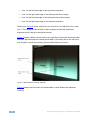
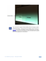
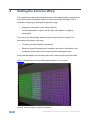
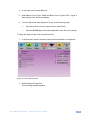
K R A ME R E LE CT R O N IC S L T D . USER GUIDE MODEL: VP-790 Blending Projected Images on a Flat Screen P/N: 2900-300215 Rev 1 Contents 1 Introduction 1 2 2.1 Setting the Basic System Optical Alignment 2 3 3 Setting Blend Width 4 Setting the 4-Corner Warp 10 5 Setting the Blend Curve 13 6 Setting the Black Level Compensation 14 7 Figures Figure 1: Basic Setup Figure 2: Image Projection Figure 3: Input Screen Figure 4: Multiunit Screen Figure 5: Two Overlapping Images on a Screen Figure 6: Two Projected Images Displaying the Horizontal Bar Test Pattern Figure 7: Blend Width Incorrectly Adjusted Figure 8: Blend Width Correctly Adjusted Figure 9: The Warp Adjust (F) Pattern Overlapped Figure 10: The Geometry Menu Figure 11: The 4-corner Menu Figure 12: Adjusting the Location of the Top Left Corner Figure 13: The Warp Adjust pattern with an S-Curve Blend Figure 14: The Multiunit menu Figure 15: The Black Level Uplift Menu Figure 16: The Reduce Black-Level Uplift Width Menu 2 3 4 5 6 7 8 9 10 11 12 12 13 14 15 15 VP-790 Blending Images – Introduction i U U U U U U U U U U U U U U U U U U U U U U U U U U U U U U U U 1 Introduction Welcome to Kramer Electronics! Since 1981, Kramer Electronics has been providing a world of unique, creative, and affordable solutions to the vast range of problems that confront the video, audio, presentation, and broadcasting professional on a daily basis. In recent years, we have redesigned and upgraded most of our line, making the best even better! Our 1,000-plus different models now appear in 11 groups that are clearly defined by function: GROUP 1: Distribution Amplifiers; GROUP 2: Switchers and Routers; GROUP 3: Control Systems; GROUP 4: Format/Standards Converters; GROUP 5: Range Extenders and Repeaters; GROUP 6: Specialty AV Products; GROUP 7: Scan Converters and Scalers; GROUP 8: Cables and Connectors; GROUP 9: Room Connectivity; GROUP 10: Accessories and Rack Adapters and GROUP 11: Sierra Products. This online guide describes how to blend two projection images accurately onto a flat, rectangular screen using the built-in functions of the VP-790. VP-790 Blending Images – Introduction 1 2 Setting the Basic System The basic system, illustrated in Figure 1, shows a video source distributed to two VP-790 units and output to two identical projectors. Figure 1: Basic Setup i One video source is distributed to both VP-790 units via a distribution amplifier (for example, the Kramer VM-2Hxl). Each VP-790 unit outputs the signal to a separate projector. To successfully blend two or more projections: 2 • Each projector should be of the same manufacture and of the same model • The projector lamps should be of the same age • The color wheels should be designed for video • The ‘dynamic gamma’ and ‘dynamic contrast’ applications should be set to off VP-790 Blending Images - Setting the Basic System 2.1 Optical Alignment 6B Figure 2 shows an example of the two 4:3 projectors being used to project a single U U 16:9 image. Figure 2: Image Projection Set the projectors so that the light from both projectors covers the whole screen area. Use the VP-790 built-in test patterns to adjust the position, zoom and focus of both projectors. VP-790 Blending Images – Setting the Basic System 3 2.1.1 Setting the VP-790 Functions Set the VP-790 functions via the OSD menu as follows: • Select Setup, Control Setup and then set the Menu Timeout to Infinite to turn off the menu timeout • Select Output, then select Resolution to set the output resolution to the native resolution of your projector to enable the VP-790 to scale the image Setting the output resolution to a resolution other than the native resolution would result in the projector re-scaling the image! • Select Output, then select Aspect Ratio to fit the aspect ratio to the display’s natural aspect ratio 2.1.2 • Select Setup, Frame Lock and select Source • Select Output, Frame Rate and select Auto Setting Multiple Units Matrix Set both VP-790 units as follows: 1. Select Input, Source and then Test Pattern. Figure 3: Input Screen 4 VP-790 Blending Images - Setting the Basic System 2. Select the horizontal grey bars test pattern in one of the two following ways: Exit the OSD menu and use the up/down arrow buttons on the front panel to cycle through the available patterns In the top OSD menu select Input, and then Test Pattern Setup and Test Pattern. Select Grey H Bars 2.1.3 Setting the Position in the Matrix 9B Define the position of each VP-790 unit in the matrix: 1. From the Setup menu, set the Operation Mode to Multiunit. Figure 4: Multiunit Screen 2. Set a 2 x 1 matrix system: Set Units Wide to 2 Set Units High to 1 3. Define the position of each VP-790 unit separately: Select the H-Position on the VP-790 unit connected to the left hand projector to 0 Select the H-Position on the VP-790 unit connected to the right hand projector to 1 VP-790 Blending Images – Setting the Basic System 5 4. Define the blend region for the VP-790 units: In the Multiunit menu, select Blend Width and set the overlap region to Right on the left hand VP-790 unit and Left to the right hand unit 5. Set Auto zoom to ON. Figure 5: Two Overlapping Images on a Screen 6 VP-790 Blending Images - Setting the Basic System 3 Setting Blend Width In the Multiunit menu: 1. Select Blend Curve Type and select Align Pattern to turn on the Blend Width alignment tool. The align pattern displays a sharp border of the blend and non-blend regions, making it easier to determine the width of the blend and to control the 4-corner set-up. Figure 6: Two Projected Images Displaying the Horizontal Bar Test Pattern Figure 6 shows two projections side-by-side displaying the Grey H Bars test pattern U U with the Blend Width alignment tool. 2. Select the Blend Width item. 3. Adjust the number of pixels to equal the optical overlap, using the alignment pattern. The default blend width is 200 pixels 4. Keep the Blend Offset value 0. The two vertical lighter stripes near the center of the screen are the blend width alignment tool. This is a visible cursor which will move as the blend width is adjusted: VP-790 Blending Images – Setting Blend Width 7 • Line 1 is the left hand edge of the right hand projection • Line 2 is the right hand edge of the left projection blend region • Line 3 is the left hand edge of the right projection’s blend region • Line 4 is the right hand edge of the left hand projection Referring to Figure 6 above, adjust line 3 to meet line 1 and adjust line 2 to meet line 4. This adjusts the blend width of each projector so that the shadowed alignment area is equal to the optical overlap. Figure 7 shows a darker vertical strip on the right hand side where the blend width has been adjusted past the overlap (blend width is too wide) and on the left hand side a lighter vertical strip showing a blend width that is too narrow. Figure 7: Blend Width Incorrectly Adjusted Figure 8 shows the view when the blend widths on both Scalers are adjusted correctly. 8 VP-790 Blending Images - Setting Blend Width Figure 8: Blend Width Correctly Adjusted i U You must set the number of blend width pixels to the same number for both processors. The blend will work properly even if the lines in Figure 8 do not align completely and even if the lines do not exactly match the overlap for one projector this just indicates that the optical zoom of the projectors is not matched. U VP-790 Blending Images – Setting Blend Width 9 4 Setting the 4-Corner Warp The images from both processors/projectors must be geometrically corrected to fit the screen and the overlapped regions must be set to align accurately. This is achieved by warping (changing the shape) the image. 1. Change the test pattern to the Warp Adjust (F). The left hand pattern is green and the right hand pattern is magenta intentionally. The color is set automatically when the position information is entered. The alternating colors help in two ways: • To clearly see each projection separately • When the geometry adjustment is complete, the parts of the pattern in the overlapping blend region will be super-imposed and appear white Inaccurate adjustment can be clearly seen as a colored fringe around the white. Figure 9 shows the view of the Warp Adjust pattern in a 2x1 matrix Figure 9: The Warp Adjust (F) Pattern Overlapped 10 VP-790 Blending Images - Setting the 4-Corner Warp 2. In the main menu select Multiunit. 3. Select Blend Curve Type. Switch the Blend Curve Type to OFF to give a clear image of the entire test pattern. 4. You can adjust the warp alignment in any of the following ways: Use the internal 4-Corner warp function (see below) Use the VP-790 Warp Generator application (see the online guide) To align the warp via the 4-corner warp function: 1. In the top menu select Geometry and then set Application to Anyplace: Figure 10: The Geometry Menu 2. Select Diagonal Projection. The following window appears: VP-790 Blending Images – Setting the 4-Corner Warp 11 Figure 11: The 4-corner Menu 3. Select a corner, for example Top Left The following window appears: Figure 12: Adjusting the Location of the Top Left Corner The Diagonal Projection menu allows you to adjust the position of the X and Y coordinates of the corners of the projected image. 4. Align the test pattern on the screen by selecting each co-ordinate in turn and moving the corner of the projected image. 5. Continue this process until the cross hatch pattern fits the screen and the central area of overlapping pattern is accurately superimposed and the pattern in this area is white. i Note that in ‘4 Corner’ warp alignment the screen must be flat and rectangular. This is important as linearity is automatically maintained between the corners and accurate alignment in the central area is only possible when the shape produced is a rectangle. You can check if your alignment is correct by changing both processor test patterns to the ‘Aspect Test’ pattern 12 VP-790 Blending Images - Setting the 4-Corner Warp 5 Setting the Blend Curve After the alignment is complete and accurate, exit the Geometry menu. 1. In the main menu select Multiunit. 2. Select Blend Curve Type and switch Blend Curve to S-Curve to give soft edge blend (see Figure 13). U U Figure 13: The Warp Adjust pattern with an S-Curve Blend VP-790 Blending Images – Setting the Blend Curve 13 6 Setting the Black Level Compensation Projectors usually output a small amount of light even when the image is black. If the amount of light is called L, then on areas of the screen where only one projector is showing its image you will have 1 x L, and where two projectors over-lap you will have 2 x L. In a dark room showing dark pictures on the screen you will be able to see the patch-work effect. The VP-790 lets you correct the difference in light leakage black level between over-lapped and non-overlapped areas on the screen. To do so: 1. Select the Aspect Test pattern to clearly see the back image. 2. Select Multiunit and then select Black Level Uplift. Figure 14: The Multiunit menu 3. Select Black Level Uplift. 14 VP-790 Blending Images - Setting the Black Level Compensation Figure 15: The Black Level Uplift Menu In this example of a 2x1 matrix, most of the list shown above is greyed out. 4. Select Non Blend Region. This allows the black level in the non overlapped area to be raised to a dark grey. 5. Adjust this level on both processors to match the level of grey in the overlapped area. 6. If you are left with a strip down each side of the center area, Go back to the previous menu and select Reduce Black-Level Uplift Width. Figure 16: The Reduce Black-Level Uplift Width Menu VP-790 Blending Images – Setting the Black Level Compensation 15 You can separately adjust the top and bottom position of the edge of the correction area to bring it in line with the edge of the visual over lapped area. 7. When this operation is complete, exit the OSD menu. 8. Select the input channel that has your picture. 16 VP-790 Blending Images - Setting the Black Level Compensation