1
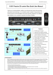
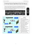
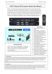
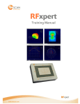
G-501 Quick User Manual
Document: G-501101
------------------------------------------------------------------------------------------------------------------------------------------------
G-500 Multi-Projector Processor Quick User Manual
Thank you for choosing GeoBox. GeoBox is an advanced dual channel video processor
with patented warp technology. It is a standalone system capable of image stacking,
video wall, edge blending and active/passive 3D demultiplexer with precise geometry
adjustment. No additional video distributor, tool or computer is required for the setup.
Features and block diagram
1. Support WQXGA/3840*1080 input
2. Precise geometry adjustment for easy
system installation and stacking
3. Support HDMI 1.4 standard 3D
formats from Blue Ray, game, PC…
4. Multiple input ports to allow flexible
input source selection
5. 10 bits scaler with high performance
de-interlace and scaling
6. Multi-projector video wall and edge
blending functions in G-502 model
7. Edge blend and image stacking for
active and passive 3D display
8. Special algorithm for perfect RH/LH
synchronization in 3D mode
9. User friendly OSD and IR remote
control. No PC is required
10. IR extender, Ethernet & RS232
control
11.3x trigger outputs for system control
12. Support curved screen 3D display
13.Support PC Nvidia 1080p/120Hz for
passive 3D display
Figure 1
Limited Warranty
This device is designed and tested to the highest standards and backed by a one year parts and labor warranty. Warranties are effective upon the
first delivery date to the end customer and are non-transferable. Warranty related repairs include parts and labor, but do not include repair of
faults resulting from user negligence, special modifications, abuse (mechanical damage), shipping damage, and/or other unusual damages. The
customer shall pay shipping charges when the unit is returned for repair. Manufacturer will pay shipping charges for return shipments to
customers.
Manufacturer does not assume responsibility for consequential damages, expenses or loss of revenue, inconvenience or interruption in operation
experienced by the customer. Warranty service shall not automatically extend the warranty period.
FCC/CE statement
This equipment has been tested and found to comply with the limits for a Class A digital device, pursuant to part 15 of the FCC Rules. These limits
are designed to provide reasonable protection against harmful interference when the equipment is operated in a residential / commercial
environment. This equipment generates, uses, and can radiate radio frequency energy and, if not installed and used in accordance with the
instruction manual, may cause harmful interference to radio communications. Operation of this equipment in a residential area is likely to cause
harmful interference in which case the user will be required to correct the interference at his own expense.
1
G-501 Quick User Manual
Document: G-501101
------------------------------------------------------------------------------------------------------------------------------------------------
Outlook and Functions
Help tips
1. Toggle on HDMI (VGA) input key will circulate between HDMI-A & HDMI-B (VGA-A & VGA-B) inputs.
2. Toggle on CH A/B keypad will circulate the OSD control between CH-A & CH-B.
3. Toggle on 2D/3D keypad will circulate between Side By Side 3D mode and 2D (or auto 3D) mode.
4. In order to avoid interference among multiple GeoBox during the installation, user can set ID number for
each GeoBox through [Options] in OSD Menu. Press number keys in Remote Controller for the control of
multiple GeoBox:
850: simultaneous control for all GeoBox
851: control GeoBox ID No. 1
853: control GeoBox ID No. 3
5. OSD Lock / Unlock: When continuously press [MENU] key in Front Panel or IR Remote Controller for 12
seconds, the OSD function will be locked to prevent from the changes of the settings by other people. To
press MENU key for 12 seconds again, it will unlock OSD and user can manipulate the OSD again.
6. Picture menu in the OSD can only be activated while the input signal is not in color [Preset Mode]. To select
[Image Properties]
[Custom]
[Save], then user can activate [Picture] menu again.
7. [Image Setup] menu will not be activated if the input source is not from VGA.
8. Procedures to do system Reset: OSD Menu [Options] [Reset] [Reset All]
9. Please select digital signals output to projector (HDMI or DVI) to avoid image position shift. If VGA output
should be selected, please set projector without implementing Auto-Adjustment in VGA input.
10. Each Internal Test Pattern Grid represents 50x50 pixels no matter which input resolution is selected.
11. Continuously press PATTERN button, internal test pattern will show different colors for easy installation:
White—Red—Green—Blue—Blank
2
G-501 Quick User Manual
Document: G-501101
------------------------------------------------------------------------------------------------------------------------------------------------
Minimum Equipment required for 3D display
1. 1x GeoBox
4. 1x 3D screen (silver matte)
2. 2x Projectors (Native resolution above XGA
5. 3D glasses (Paired with polarizer)
with HDMI input connector)
6. 3x HDMI cables
3. 2x polarizers (For RH & LH eyes)
7. Video source with 3D content
Installation process for 3D display
1. Install projectors & screen to let projection images a little over the screen without going through GeoBox.
Make sure to avoid heat ventilation interference in the setup.
2. Connect all the cables and GeoBox RH output connects to RH projector and LH output to LH projector.
3. Reset GeoBox to factory default settings via OSD [Option] menu to ensure no unexpected settings.
4. Set polarizer into RH & LH projectors before geometry alignment. Make sure the RH/LH polarizers are set
in correct projector, direction and angle with distance of 5-15cm to the lens to avoid thermal damage.
5. Blue Ray player should be set at AUTO 3D (or 1080p@24Hz) for 1080p frame packing 3D display.
6. Turn on all devices. Some projector will search input source several times due to input timing change and
HDCP validation. GeoBox will automatically connect to input source. Then the screen will show up with
double images. To set HDMI as projector input may reduce the time for input searching. If no input source
is detected, GeoBox will go into power saving mode. The screen will show [Power Saving Mode] message.
7. Select correct input source and set output resolution to match projector native resolution.
8. Make sure two projectors are in good focus and have the same settings.
9. Use [OSD Time] hot key in remote controller to set OSD Time Out to [Off] to show OSD & grid pattern all
the time during image alignment and 3D settings period.
10. Align two projector images together via [4 Corner] adjustment.
11. [3D Properties] setting to get correct input format and 3D settings.
12. Test the final result and 3D performance.
3
G-501 Quick User Manual
Document: G-501101
------------------------------------------------------------------------------------------------------------------------------------------------
13. Two projector Image alignment procedures using remote controller
1. Power on the system after installation, double
images will appear on the screen.
2. Set [OSD Time Out] to [Off] to show OSD & grid
pattern all the time during system setting period.
1. Press [Pattern] key to show Grid pattern in CH-A.
Continually press [Pattern] key will change the
grid color.
nd
2. Press [CH A/B] key to switch to the 2 channel,
then press [Pattern] key again to show grid
nd
pattern in the 2 channel.
3. Left figure shows CH-A in Red and CH-B in
Green color.
1. Press [4 Corner] key will show [4 Corner] OSD
menu in one channel and another channel still
retain grid pattern.
2. User will see [Channel B] indicator at the bottom
right of the OSD to show the channel to be
adjusted.
3. Select the corner to be adjusted by OSD direction
keys--[Top Left] is selected in the example.
1. After press [OK] key, a Green Mark will be
showed at the corner to be adjusted.
2. Left figure shows CH-B [Top Left] corner is
selected and under adjusting.
3. Use OSD direction keys to adjust the position of
the corner into screen border.
1. When finish the adjustment in Top Left corner in
CH-B, don’t press [OK] key.
2. Press [CH A/B] key to switch to CH-A.
3. [4 Corner] OSD menu for CH-A will be showed
with [Channel A] indicator at the bottom right of
the OSD.
4. Select [Top Left] corner and press [OK] key, a
RED Mark will be showed at [Top Left] corner to
indicate the corner to be adjusted.
4
G-501 Quick User Manual
Document: G-501101
-----------------------------------------------------------------------------------------------------------------------------------------------Use OSD direction keys to adjust CH-A [Top Left]
corner to match CH-B [Top Left] corner, then press
[OK] to go to next step.
(If grid pattern disappears, press [Pattern] & [CH A/B]
keys to activate grid patterns in both channels)
1. After press [OK] key, it will show [4 Corner] menu
again in CH-A.
2. Select the second corner to be adjusted.
3. Press [OK] key, then it will show Red Mark at the
selected corner.
4. To adjust the position of the corner to match the
screen border by direction keys.
5. Press [CH A/B] to switch to CH-B and do the
same corner adjustment process.
After all corner positions have been aligned together
with the screen. The grid patterns from CH-A & CH-B
will overlap together and show only one grid pattern.
1. Press [Exit] in remote control to turn off grid
pattern in one channel.
nd
2. Switch to 2 channel by [CH A/B] key, then
nd
press [Exit] again to exist from the 2 channel.
3. User will get clear image after this process, if not,
please fine-tune the alignment. Then user can
start [3D Properties] setting.
The above [4 Corner] alignment process can be applied to both 3D alignment and Image
Stacking in flat screen display. If curved screen 3D display is required, user needs to use
[Warp] function in OSD menu to align the images from two projectors together. [Curved]
function includes [Shift] (4 Corner adjustment), [Corner] curve, [Edge] curve and [Center]
curve adjustments.
5
G-501 Quick User Manual
Document: G-501101
------------------------------------------------------------------------------------------------------------------------------------------------
Procedures for 3D display setting in GeoBox
1. After [4 Corner] adjustment, to activate [3D
Properties] in OSD to select 3D formats.
2. Select [Automatic] if the 3D signal is standard 3D
formats from Blue Ray player.
3. Select [Side By Side] or [Top-Bottom] based on
user’s 3D input sources.
1. Activate [Identify] menu to show “R & L”
characters on the screen simultaneously
to verify the final 3D settings in the
system.
2. RH eye should see only “R” and LH eye
should see only “L”.
1. If it is not the result, then to set [Output Format] in
OSD menu is required.
2. Please swap [Left Eye Frame] and [Right Eye
Frame] in both RH/LH output channels to see the
right “R” & “L” characters in both eyes.
3. Complete system check is required if the problem
still existing.
If still can’t verify “R” & “L” characters in both eyes, please check below again:
1. Is the screen for 3D display?
2. Are the Glasses and polarizers the same types and paired for the RH & LH eyes?
3. The default output setting of CH-A is for RH eye and CH-B is for LH eye. Please check from [Output
Format] menu as above figure and make sure [Right Eye Frame] is set in CH-A and [Left Eye Frame] is
set in CH-B.
4. Is the Blue Ray player set to [Auto 3D] or [1080p frame packing] mode to deliver 3D signal out?
5. If Side by Side or Top-Bottom 3D formats are used, please check the aspect ratio in video source output
to make sure GeoBox will receive full screen image.
6. Is there any HDMI or signal source compatibility issue and only one projector shows image?
After above procedures, apply 3D signal source and wear 3D glasses, then user can enjoy the most
comfortable and healthy 3D system. It is the best solution for children with minimum harm to eyes.
6
G-501 Quick User Manual
Document: G-501101
------------------------------------------------------------------------------------------------------------------------------------------------
Projector installation and setting guide for 3D display
1. Two projectors can be installed side by side or top-bottom. Closer position will reduce 4 corner adjustment
ranges and reduce the loss of the image resolution and brightness. Please make sure ventilation hot air will
not affect each other.
2. Maximum [4 Corner] adjustment range in each corner is ±256 pixels horizontally (max. 300 pixels in Left +
Right) and ±200 pixels vertically (Top + Bottom). For output resolution above 1400 x 1050, the range will be
H: ± 150 & V: ± 100. Please make sure the installation of the projectors can meet this limits. Each grid
pattern is 50x50 pixels before implement 3D function and will be 50x100 pixels after implement 3D.
3. GeoBox can support passive 3D display on curved screen through [Anyplace]
[Curved] function in OSD.
4. The output brightness of the projector will differ in different Display Modes. User needs to select one with
higher brightness and enriched color. “Presentation” mode will give higher brightness but the color will differ
from original. sRGB will give user better color but the output brightness is usually comparative low. Two
projectors should have the same color settings to get the best 3D performance.
5. During the installation, the distance between the polarizer and the projector should be over 5cm to avoid
thermal damage due to high temperature from the projector. Higher lumens projector will create more heat
and the distance should be larger. The polarizer can only tolerate up to about 60~70℃.
6. If 2D & 3D display is required in the same setup, user can keep the polarizer in the system but the total
brightness of the system will be lower. If user wants to enhance the brightness, there should be a
mechanism to remove the polarizers while the system switching to 2D display. For 2D display, it is
necessary to do different geometry alignment because the polarizers will change the light path. If necessary,
user can do alignment based on 2D display without polarizer and put on polarizers for 3D with the same
alignment settings because 3D display allow small geometry shift. Different settings in geometry adjustment
can be stored in GeoBox [Profile] menu and recall through OSD.
7. GeoBox HDMI connector may be damaged by an unqualified HDMI cable. Please use qualified HDMI cable
and carefully plug in and out.
8. Pay attention to the HDMI compatibility due to different cables, equipment and connection distance. If the
distance is too long, HDMI extender shall be considered. It may extend the distance up to 50m to 100m.
Screen selection guide for 3D display
1. Silver Matte screen is required for polarized 3D display. Spectrum filter 3D system can use conventional
screen. Some factors are important in polarized 3D display screen:
i. The ability to retain polarization: higher value will have less ghost cross talk.
ii. Gain value: high value will have better brightness but may have viewing angle and hot spot issues.
iii. Flatness of the screen: Viewer may see wave screen and dis-alignment in geometry, especially in short
throw ratio projectors. It may be OK for 3D display but it will yield blurred image in 2D display.
2. The prices in different 3D screens have big range. Paint for 3D screen is available in the market.
3. If 2D & 3D display is required. User can select a screen with 2D/3D ability in the market.
4. Cheap silver paint and clothes with silver paste coating can be used as a temporary means to verify the
function of the 3D system if no 3D screen is available.
7
G-501 Quick User Manual
Document: G-501101
------------------------------------------------------------------------------------------------------------------------------------------------
Projector selection guide for 3D display
1. It is not necessary to use expensive projectors with lens shift or special geometry alignment rack because
GeoBox can do pixel by pixel precise geometry adjustment.
2. A normal projector can be chosen for 3D display (no need to have 3D ready). Usually, XGA resolution will
create acceptable 3D video quality. A projector with higher native resolution, output brightness and contrast
ratio, will yield better performance similar to Movie Theater.
3. The output light from a projector with 3x LCD micro display (such as Epson) or LCOS (JVC or Sony) may
preserve polarization and the polarizer and glasses need to be carefully selected. Linear polarized system
can be used in Epson 3x LCD projector but circular polarized system can’t. Optical spectrum type filter and
glasses can be an alternative in this case. DLP type projector is easier in polarizer and glasses selection.
4. The projector with throw ratio under 0.8 is not recommended because it will be more sensitive to the flatness
of the screen and create difficulty in the installation.
5. DLP projector for PC graphics display purpose may use different color wheel for higher brightness but
degrade the color performance. Please select video projector with HDMI input for home theater application.
6. For use in public area, the projectors with higher brightness should be considered. Projector with more than
3,000 lumens will be acceptable in limited ambient light controlled area. More than 4,000 lumens will create
better 3D effect. Projector with full HD resolution and 2,000 lumens will be recommended for home theater.
Other Important Tips for 3D display
1. The final brightness to the eyes will be reduced due to 3D polarizer and glasses. Passive 3D brightness to
the eyes will be about 3x if compared with the same projector used in active (shutter) 3D system.
2. Incorrect aspect ratio adjustment of signal source may cause abnormal 3D display when the 3D format is
Side by Side or Top-Bottom.
3. Pair the glasses and polarizer is required: If viewer wears 3D glasses and sees the light from lamp through
one polarizer via RH eye with different side, direction and angle, viewer will see below conditions:
i.
If RH eye can see through the polarizer at any side, direction and angle, then this polarizer is not for RH
eye. It should belong to LH eye projector.
ii.
If viewer can’t see through or only see minor light at some angle or direction, then it can be for RH eye
projector. The side faced to the eye should be pointed out to the screen and the polarizer should be
installed at the same angle as viewer sees minimum light through.
4. GeoBox doesn’t have VGA output. Using HDMI to VGA conversion box to connect projector through VGA
port is not recommended because projector may change the geometry alignment due to “Auto Setting”
during system booth up stage, unless “Auto Setting” function in projector can be turned off.
5. It is possible for the system to hung up during image adjustment. In this case, system will restart within one
minute. User can also turn OFF/ON the system to restart again. This kind of situation will not happen once
the complete system setup is finished. It will not affect the stability of the whole system.
6. If 3D setting in Blue Ray is not correct, GeoBox will not be detected and 3D signal can’t be delivered to
GeoBox. Please set Blue Ray at auto 3D or 1080p@24Hz frame packing.
7. Usually front projection 3D screens will be silver (aluminum) surfaced in polarized 3D system unless optical
8
G-501 Quick User Manual
Document: G-501101
-----------------------------------------------------------------------------------------------------------------------------------------------spectrum filter system from Dolby or Infitec has been used. Optical spectrum filter system can use normal
2D screen and minimized the ghost effect (crosstalk) but the filter and glasses will be in higher prices.
8. There are many kinds of 3D polarization system with different polarizing angles or directions. User needs to
check whether the glasses can match exactly with polarizer being used for the projectors.
9. Please note that head tilting and different viewing angles will affect crosstalk in linear polarization system.
10. It is necessary to recheck the overlap condition of the projectors if there is any output mode change. If
necessary, please use [Profile] to store different settings.
11. In Side by Side or Top-Bottom 3D input mode, user may not see full OSD display from the video sources
on the screen. To set correct video source before implement 3D mode.
12. Although GeoBox is the most advanced and comfortable 3D control system, 3D screen, polarizer and
glasses are also important factors for a perfect 3D system.
Flat screen Edge Blending installation guide (only available in G-502 model)
1. Please use [Excel Spread Sheet] provided by dealer to calculate the number of projectors and overlap pixels
between projectors. Make sure enough brightness on the screen with aspect ratio matching the content.
2. Placement of Projectors:
Select projectors with higher contrast ration (above 3000:1 is recommended) and set projectors at
reasonable distance from the screen with 200-500 overlap pixels between two projectors.
Use removable tape as temporary marks to show the display ranges for each projector. Each
projector should have the same display size. Otherwise the grid size in each projector will be different
and the blending image will become blurred.
To project each projector a little over the display range for further geometry adjustment.
To set parallel vertical or horizontal overlap edges between 2 adjacent projectors will get better video
quality in Edge Blending image.
3. Projector setting:
Reset projector to default setting
Disable Auto Keystone function and set new keystone value to let vertical edges in adjunction images
in parallel vertically.
Select sRGB Display Mode will reduce the color difference in overlap area.
Use projector internal color adjusting function to adjustment the color variation among projectors.
4. GeoBox Setting
Reset GeoBox to default setting.
Select the input source and best output resolution to match projector native display resolution.
Set [OSD Time Out] to [OFF] to maintain the display of OSD and Internal Test Pattern during the
installation period.
To set Color in [sRGB] or [Neutral]. Preset Mode will create better Edge Blending result. (OSD menu
[Image Properties] [Color] [Preset Mod]e [sRGB/Neutral])
5. Four Corner geometry Adjustment
To adjust the corner positions in each projector to match preset marks in the screen. After all projectors are
projecting at the right preset positions, then to do accurate position fine-tune is required to let all the grids in
overlap area able to align perfectly. If the system is for 3 projector edge blending, the center projector should
9
G-501 Quick User Manual
Document: G-501101
-----------------------------------------------------------------------------------------------------------------------------------------------be aligned first then to align the rest two projectors to match center projector. To use projector internal
keystone to get vertical edges in center projector will be easier to get better edge blending result.
If the screen is curved or not flat and the grids in overlap area can’t be perfectly aligned, then additional
GeoBox is required for curve (warp) alignment. Please contact dealer for more details.
6. Video Wall setting (Image split and allocation)
After [4 Corner] adjustment, video wall setting is required. The functions of video wall are as follows:
Split the image for different projectors
Determine the location of the image for each projector
To set proper overlap region in the edge between projectors
Example for 3x2 matrix edge blending:
Select [Horizontal Zoom]
[3] to split the
image for 3 projectors horizontal edge
blending configuration.
Select [Vertical Zoom]
[2] to split the
image for 2 projectors vertical edge
blending configuration.
Select [Horizontal Pan ] [1] and [Vertical
Pan] [2] to assign the projector to [Bottom
Left] position
Select [Horizontal Pan ] [3] and [Vertical
Pan] [1] to assign the projector to [Top
Right] position
Use Overlap function to align the zoom ratio
and image position between adjacent
projectors. Correct adjustment will eliminate
double image in the screen
Left figure:
Before Overlap adjustment: Double image in
the center overlap region.
10
G-501 Quick User Manual
Document: G-501101
-----------------------------------------------------------------------------------------------------------------------------------------------Left figure:
After Overlap adjustment: No double image in
the center overlap region.
An [Excel Spread Sheet] can be provided for the calculation in different setup. Below is the calculate result
of Video Wall [Overlap Value] for 2 projector edge blending. If no [Excel Spread Sheet] can be used, user
can see the image changes of projectors during OSD Overlap value adjustment and determine the value.
Video Wall [Overlap] value in dual projector horizontal edge blending
Input to
GeoBox
Output
Overlap 5 grids
Overlap 6 grids
Overlap 7 grids
Overlap 8 grids
to
projector
Overlap
Aspect
Overlap
Aspect
Overlap
Aspect
Overlap
Aspect
XGA
XGA
51
2.34
88
2.28
106
2.21
124
2.15
720p
XGA
89
2.34
110
2.28
132
2.21
155
2.15
1080P
XGA
133
2.34
165
2.28
198
2.21
233
2.15
XGA
720P
55
3.21
68
3.14
81
3.07
95
3.0
720p
720P
69
3.21
85
3.14
101
3.07
119
3.0
1080P
720P
104
3.21
127
3.14
152
3.07
178
3.0
XGA
1080p
36
3.32
43
3.28
51
3.23
60
3.19
720p
1080p
45
3.32
54
3.28
64
3.23
74
3.19
1080P
1080p
67
3.32
81
3.28
96
3.23
112
3.19
Remarks:
1. "Overlap" means the pixel # in Video Wall Overlap in the overlap region in each projector. LH
projector needs to apply the value to RH Edge and RH projector needs to apply to Left Edge.
2. "Aspect" means the output image [Aspect Ratio] between horizontal size and vertical size.
3. The Edge Blending Value is the # of overlap grids x 50 (i.e. 6 grids means overlap 300 pixels)
4. Overlap region less than 250 pixels can be implemented but the edge blending quality will be
more difficult to control.
7. Video Wall [Overlap] setting is to decide the cropping area for each projector so that two projector overlap
regions can match together with the right position and scaling ratio. It is not a real overlap pixel # between
adjacent projectors. User will see double brightness in overlap region before further [Edge Blending] setting.
8. Edge Blending setting is to let two images in overlap region merged gradually in different directions to
become one seamless image. The setting value is based on the actual overlap pixel number. For instance, if
the overlap is 6 grids, then the setting value is 6x50=300 pixels because each grid is 50x50 pixels in internal
test pattern. Below are the procedures for Edge Blending value setting.
11
G-501 Quick User Manual
Document: G-501101
-----------------------------------------------------------------------------------------------------------------------------------------------Activate [Edge Blend] menu under [Anyplace]
5 function under [Edge Blend] menu for edge
blending and quality fine tune.
Select correct Edge of the overlap region:
Select Right Edge for LH projector in dual
projector edge blending and select Left Edge
for RH projector.
Set Edge Blending values in the overlap edge based on the overlap pixels (each overlap grid
represents 50 pixels—5 grids mean overlap 250 input pixels).
Fine tune color
Select different [Gamma] and LUT values and check video performance.
Set right [Offset] value to compensate black level difference.
Eliminate the banding line via [Shift] blending position.
9. Image quality fine tuning
The final performance will be a combination of many factors—projector characteristics, projector
setting, screen, ambient light, GeoBox setting. Banding in overlap area under dark environment is
caused by low contrast ratio projectors due to light leakage in the projector optic system.
The factors affect final image quality
i.
GeoBox settings:
a、 Edge Blending: Gamma, Shift, Offset, Gain
b、 Image Properties: To select Preset Mode to sRGB, Neutral or Bluish
ii.
Projector:
a、 To adjust installation position of the projector and deduce keystone angle.
b、 Increase Overlap region & Reduce off axis angle
c、 To change Display Mode, usually sRGB will get the best result.
d、 Try different color settings. If necessary to use 3D color adjustment in the projector.
e、 To implement 3D color adjustment.
iii.
Screen: To use lower gain value screen.
12
G-501 Quick User Manual
Document: G-501101
------------------------------------------------------------------------------------------------------------------------------------------------
Projector image stacking procedures
1. Image stacking is a cost effective solution to increase the brightness of the projection system. User can use
three low cost projector with 3,500 lumen to stack up to 10,000 lumens easily at much lower cost.
2. One G-501 can do 3 projector stacking. If 3 projector stacking is executed, it is necessary to add one video
distributor at the front of G-501. The first projector should be connected directly to HDMI splitter with native
raw signal without processing by GeoBox and the other two projectors should be connected to RH & LH
output ports of GeoBox.
3. To apply grid pattern from external signal source during geometry alignment process.
4. To do geometry adjustment in the first projector to let the image match the screen borders through keystone
correction or lens shift function inside the projector.
5. To use [4 Corner] adjustment to align the images from the 2nd and 3rd projectors on to the first one.
6. For curved screen stacking, only two projector can be used through [Warp] function in GeoBox unless the
first projector can support curved screen display as well.
7. If the screen is not flat enough, the image sharpness will be reduced.
Technical support
Please check more technical information in www.vnstw.com website:
Technical support: Steve Wang, HH Lin
Tel: +886-2-8751-2785 ext. 301/305
E-mail: [email protected]
Website: www.edi-tw.com
13