1
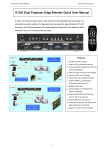
G-302 Quick User Manual Document: G-302101 ------------------------------------------------------------------------------------------------------------------------------------------------ G-302 Dual Projector Edge Blender Quick User Guide Outlook and Functions Procedures for 2 projector edge blending System configuration 1. To use the same projectors and install with the same settings. Disable auto keystone and set color in standard or sRGB display mode to reduce the possible banding in overlap region. 2. To project the image to the screen with the image edge in the overlap area vertically. If necessary, to use keystone correction function to get vertical lines. It will help the final video quality after edge blending. G-302 only can do flat screen edge blending with two projectors. If more projector edge blending is required, G-502 should be used. For curved screen edge blending, G-104 should be applied. Dual projector flat screen edge blending A. Procedures and key points 1. Reasonable overlap region is required In XGA projector, we recommend to overlap at least 250 pixels for easy quality fine-tune. It means the overlap region is about 13.9% in the complete image (250/(1024*2-250)=13.9%). In the case of full HD projector, the overlap region is about 400~600 pixel (11.6%~18.5%). 2. The images from two projectors must have the same grid size Two ways for final grid adjustment (4 Corner adjustment) to let all grids with the same size: a. To calculate the necessary size of the images from two projectors. The image size from two projectors must be the same. To put temporary marks on the screen to indicate the final location of the images and align the images to meet the required size. 1 G-302 Quick User Manual Document: G-302101 -----------------------------------------------------------------------------------------------------------------------------------------------b. The second way is to mark the center line of the screen and let CH-A & B has the same grids over the center line and let all grids in both CH-A & B be perfectly aligned. 3. Geometry alignment a. Mark the center points of the screen b. Connect CH-A output to RH projector and CH-B output to LH projector. Install projector to project image a little over the screen with recommended overlap area. c. Reset GeoBox, set [Menu Time Out] to “0”. d. Activate [Pattern] menu and use [CH A/B] to switch between CH-A & CH-B to show internal grid pattern with different colors. e. Use [CH A/B] to select one channel for geometry adjustment, active [4 Corner] to do geometry alignment in the first channel, then in the second channel. f. Image location fine-tune is required to let the images from both projectors with the right locations and same size. To let all grids in overlap area perfectly be aligned together will ensure the best geometry adjustment result. (Note: if the screen is not flat enough, then it will have some dis-alignment in non-flat area and may cause blurred image. For curve edge blending G-104 model is recommended to get best result) 4. Set pixel number for Edge Blending a. Pixel number in edge blending is calculated based on the grids number in overlap region. b. Each grid pattern represents 50x50 pixels in size when G-302 output resolution is full HD. The total overlap is 50 (pixel) x 10 (grid) = 500 pixels if two images are with 10 grid overlap. If the output resolution is XGA, then the overlap region represents 500/1920x1024=267 pixels c. This overlap number should be applied in the Edge Blending in below procedures. 5. Extend the image for two projectors a. After set correct Edge Blending pixel number, G-302 will automatically calculate the image cropping area for each projector. b. To activate [Extend] OSD menu will split the input image, crop the right image area and assign to each projector to finish the complete Edge Blending procedures. 6. Image fine tune After the above procedures, user has already finished edge blending procedures. If viewer still sees obvious banding effect in overlap region. Further image fine-tune is required. B. Geometry adjustment—step by step 1. Projector installation 1. Connect CH-A to RH and CH-B to LH projector 2. Install projectors projecting a little over the screen with overlap region of 250~400 pixels. 3. Reset GeoBox and set [Menu Time Out] to “0” to show OSD & grid pattern constantly. 4. Activate [Pattern] & [CH A/B] keys to show different color grid pattern for easy alignment. 2 G-302 Quick User Manual Document: G-302101 -----------------------------------------------------------------------------------------------------------------------------------------------If no input signal is connected, the screen will show [Power Saving Mode] and it will show Blue background when OSD is activated. Each grid size is 50x50 pixels in full HD output resolution. If GeoBox output resolution is XGA, then each grid represent a size of 26.7x26.7 pixels (50/1920x1024=26.666) 2. Start [4 Corner] adjustment in one channel (CH-B is firstly selected in below example) 1. Activate [4 Corner] key in CH-B. An indicator (CHANNEL B) will be showed at the bottom right of the OSD. 2. Select one corner and press [OK] to start 4 corner adjustment in CH-B 1. A green Mark at the corner (Top Left) to show the corner to be adjusted. 2. Using OSD direction keys to move the corner position into screen border. Limitation in adjustment range: The adjustment range in the corner will be varied in different output resolution from GeoBox. For output resolution under 1400x1050, the range will be ±256 pixels in horizontal and ±200 in vertical direction. For XGA resolution, the adjustment range is about 9.5 grids in horizontal and 7.5 grids in vertical directions. At full HD output, the range will be ±200 (4 grids) in horizontal and ±100 pixels (2 grids) in vertical directions. 1. Press [OK] key will activate [4 Corner] menu again 2. Select next image corner to be adjusted (Bottom Left is selected in left figure). 3. A green Mark is showed at the corner to be adjusted. 1. To move [Bottom Left] corner into the screen border. 2. A green Mark in bottom left showed the adjusting result 3 G-302 Quick User Manual Document: G-302101 -----------------------------------------------------------------------------------------------------------------------------------------------Apply the same procedures as above to adjust [Top Right] and [Bottom Right] corner of the image and let the image of CH-B become rectangular inside the screen borders. 3. Start [4 Corner] adjustment in another channel (CH-A) 1. After finish geometry alignment in CH-B, press [CH A/B] to switch to CH-A OSD menu. 2. [4 Corner] adjustment menu will appear. If no [4 Corner] menu shows up, please press [4 Corner] menu again in remote controller 3. Then select the corner and press [OK] to do corner position adjustment 1. If finish the last Corner (Bottom Right) in CH-B and press [CH A/B] to switch to CH-A directly, OSD menu will show the same position of the last adjusted corner (Bottom Right). Ppress [OK] key to pop up grid pattern with a Mark at the corner to be adjusted. 2. To move the image into screen border and follow the same procedures to adjust all corner at CH-A. Left figure shows both CH-A & CH-B corners had been adjusted to rectangular with some overlap at the center of the image but the grids in CH A & CH-B are not overlapped together. 4. Geometry fine-tune The grids at the overlap region are still not aligned together. It means the size of the grid in CH-A & CH-B may still not be the same. In this case, it will create burred image in overlap region. 1. Continuously fine-tune 4 corners in the overlap region from CH-A & CH-B to let the grids in two projectors be perfectly aligned as showed in left. 2. Note: once the grid sizes in two projectors are the same size with the horizontal lines aligned together, it is still possible to show good edge blending image. 4 G-302 Quick User Manual Document: G-302101 -----------------------------------------------------------------------------------------------------------------------------------------------1. Press [Exit] key in remote controller or [Menu] key on front panel to disable grid pattern, then press [CH A/B] key to disable grid pattern in another channel. If grid pattern still exists, then press [Exit] to disable it. 2. After disable grid pattern the images from two projectors will show at the same time with some overlap. (The grid in left figure comes from signal source but not from internal grid pattern) CH-B CH-A C. Set pixels number for edge blending 1. In the above example, the overlap region is 14 grids (calculated from internal grid pattern but not video source). Each grid pattern represents 50x50 pixels in size under the condition that the output resolution of G-302 is set at 1920x1080 output resolution. 2. The total overlap is 50 (pixel) x 14 (grid) = 700 pixels in above example. 3. If the output resolution is XGA, then the overlap region represents 700/1920x1024=373.3 pixels 4. This overlap number should be applied in the Edge Blending in below procedures The native resolution of the projector in the example is XGA and the output resolution of G-302 is also set at XGA to get the best video performance. Therefore 373 pixels edge blending shall be applied. 1. Activate [Edge Blend] OSD menu under [Anyplace] in CH-A (user can also select CH-B) 2. Edge Blending area in CH-A is at LH side, therefore [Left Edge] for CH-A (RH channel) shall be selected and set edge blending pixel value: at 373 (based on the previous calculation). 1. Press [CH A/B] to switch to CH-B 2. Select [Right Edge] and set edge blending value at the same value as CH-A at 373. D. To extend the image into two projectors 1. Activate [Extend] under [Edge Blend] OSD menu 2. Press [OK] to enter this menu and [Enable] extend function 3. The image will automatically edge blend together as show below 5 G-302 Quick User Manual Document: G-302101 -----------------------------------------------------------------------------------------------------------------------------------------------Before [Enable] extend function After [Enable] extend function E. To fine-tune [Overlap] value under [Edge Blend] menu 1. [Overlap] value will be automatically created while the [Edge Blend] value is set to G-302 under the condition that no any other [Overlap] value has been input to GeoBox before set [Edge Blend] value. If double image or blurred image appears in overlap area as showed in left figure, it means the setting in [Edge Blend] or [Overlap] value is not correct. Further adjustment is required. 2. Possible reasons that the [Overlap] value is not correct: a. GeoBox didn’t execute Reset procedures and some old [Overlap] value is set in GeoBox. b. The [Edge Blend] value calculation and setting is wrong. After automatically calculation, it gets wrong [Overlap] value. c. User had kept value in [Overlap]. In this case, GeoBox will not automatically create new value. 3. How to fix it: a. If the image is just a little blurred in overlap area, try to increase or decrease small step of [Overlap] value in both CH-A & CH-B shall make the image clearer. In this case, it is unnecessary to recalculate [Edge Blend] value again. b. Check the accuracy in [Edge Blend] value calculation. Make sure that different output resolution setting in G-302 will have different values although it show the same number of overlap grid pattern. c. Activate [Overlap] OSD under [Edge Blend] menu and check the value settings in both CH-A & CH-B, then increase or decrease the value to see which direction will reduce the difference in double image. To activate [Overlap] menu under [Edge Blend] and re-adjust the [Overlap] value will let the image align together as normal image. 6 G-302 Quick User Manual Document: G-302101 -----------------------------------------------------------------------------------------------------------------------------------------------F. Fine-tune overall Edge Blending performance The final performance will be a combination of many factors—projector characteristics, projector setting, screen, ambient light, GeoBox setting. The follows are the functions that should be tried during the final fine-tune stage. 1. GeoBox: Edge Blending: Gamma, Shift, Offset, Gain Image Properties: To select Preset Mode to sRGB or Bluish 2. Projector: To use projectors with higher contrast ratio will reduce the light leakage in overlap region. This light leakage can only be compensated by adjusting the black level in non-transition area. To adjust installation position of the projector: i、 Increase Overlap region ii、 Reduce off axis angle iii、 Let two image border at overlap region before vertical lines before GeoBox geometry adjustment To change Display Mode and try different color settings. To implement 3D color adjustment. 3. To use lower gain value screen to reduce the view difference in different view angle. Technical support Please check more technical information in www.vnstw.com website: 1. G-104 Curve Edge Blending Quick User Manual 7