Download iPAC 5070 user guide

Transcript
PAC-5070 User Guide
Introduction:
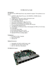
PAC-5070 is ARM9-based Linux ready industrial Programmable Automation
Controller. The key features are as follow:
1.
2.
3.
4.
5.
6.
7.
8.
9.
10.
11.
12.
13.
14.
15.
16.
17.
ARM920T ARM Thumb Processor with 200MIPS at 180MHz, Memory Management Unit
16-KByte Data Cache and 16-KByte Instruction Cache
64MB SDRAM, 16MB Flash on board
Two 10/100 Mbps Ethernet
Two USB 2.0 full speed (12 Mbps) Host Ports
Multimedia Card Interface for SD memory card
One RS-485, One RS-232 and One serial console port
4 isolated analog inputs
Input type: mV, V, mA
Input range: +/- 150mV, +/- 500mV, +/- 1V, +/- 5V, +/- 10V,
0~150mV, 0~500mV, 0~1V, 0~5V, 0~10V, 0~20mA
1500 Vdc isolation
8 opto-isolated digital inputs
8 Darlington-pair digital outputs
9 to 40VDC power input
Pre-installed Standard Linux 2.6 OS
GNU tool chain available in Artila CD
DIN RAIL mounting
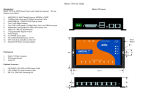
PAC-5070 Layout
Power
(9~40V)
+
-
LAN1
LAN2
USB
Reset
Digital Output
118mm
Buzzer
Packing List
182mm
1.
2.
3.
PAC-5070
CBL-F10M9-20: 10-pin header to DB9 male cable for RS-232 x1
Artila CD
RS-485
RS-232 Serial Console Isolated Digital Input Isolated Analog Input
Pin Assignment and Definition
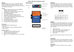
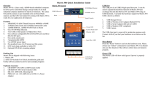
Reset Button
Press the “Reset” button to activate the hardware reset.
You should only use this function if the software does
not function properly.
COM1: RS-485
Data+ Data-
Power LED
The Power LED will show solid green if power is properly applied
Ready LED
The Ready LED will show solid green if iPAC-5010
complete system boot up. If Ready LED is off during
system boot up, please check if power input is correct.
Turn off the power and restart iPAC-5010 again. If
Ready LED is still off, please contact the manufacture
for technical support.
LAN1/LAN2 LED
When Ethernet port are connected to the network, Link/
Act will show solid green and if there is traffic in the
Ethernet, this LED will flash
Serial Port LED
These three dual color LEDs indicate the data traffic at
the serial ports. When RXD line is high then RED
light is ON and when TXD line is high, GREEN light
is ON.
Ethernet Port (LAN1/LAN2)
Serial Ports:
COM1: RS-485 (Data+, Data-)
COM2: RS-232 with full modem control
COM3: RS-232 with RxD TxD (Console)
COM2: RS232
COM3: Console
2 4
1 3
6
8 10
5 7
9
Data+ is pull up to 3.3VDC
with 10K Ohm resistor
Data– is pull low to ground
Termination resistor is not included. User can add a 120
Ohm resistor shunt with D+ to
D– if necessary
Pin COM2 COM3
1
DCD
N/C
2
DSR
N/C
3
RXD
RXD
4
RTS
N/C
5
TXD
TXD
6
CTS
N/C
7
DTR
N/C
8
N/C
N/C
9
GND
GND
10
N/C
N/C
Serial console port (COM3) is very helpful to perform
system configuration and debug. When you forgot
password or network IP address, serial console provide
an easy way to access iPAC-5010. To access serial
console port, you can use CBL-F10M9-20 to convert 10
-pin header to RS-232 DB9 male connector and use a
null modem adaptor for PC RS-232 interface. Use any
terminal software such as hyper terminal and setting as
follow:
Baud Rate: 115200
Data bits: 8
Parity: N
Stop bit: 1
Terminal type: ANSI
Once you power up PAC-5070, you will see the console
message appears.
RS-232 DB9 Male Connector
Pin RS-232
1
DCD
2
RXD
3
TXD
4
DTR
5
GND
6
DSR
7
RTS
8
CTS
9
N/C
Pin
USB
1
Vcc1
2
Vcc2
3
Data1-
4
Data2-
5
Data1+
6
Data2+
7
GND
8
GND
9
N/C
10
N/C
USB Port:
2 4
1 3
6
8 10
5 7
9
Vcc1,Vcc2: +5Vdc
GND: Ground
Power Input Connector (J3)
PAC-5070 uses +9VDC to 40VDC power and input from J3
connector. Auto-polarity and surge protection are included
in power input circuitry of PAC-5070 to provide power protection to PAC-5070.
Digital Input Connector
The 8 channel isolated input are equipped with 2500 Vrms
photo coupler isolator. Four of the channels form a group
and share the same common ground. The specification of the
isolated input channels are:
Analog Input Connector
Each of the 4 channels isolated analog input can be configured
as various input range and the common features are show as
follow:
Effective Resolution: 16-bit
Channels: four differential input channels
Input Type: mV, V, mA
Input Range:
Uni-polar:0~150mV, 0~500mV, 0~1V, 0~5V, 0~10V
Bi-polar: +/- 150mV, +/- 500mV, +/- 1V, +/- 5V, +/- 10V
Current: 0~20mA
Sampling rate: 10~100 samples /sec
Input Impedance: 20 M Ohm
Accuracy: +/- 0.1%
CMR: 50/60 Hz 100dB
Isolation: 1500Vrms (Three-way)
Logical High: 5~24Vdc
Logical Low: 0~1.5Vdc
Input resistance: 1.2KOhms @0.5W
Response time: 20us
Isolation: 2500Vrms
+ -
Digital Output Connector
The digital output are equipped with 8 darlington pair transistors (Allegro UDN2981A) to switch the external relay or solenoid. The internal transient-suppression diodes permit the
drive to be used with inductive load. The source voltage of
the drive is from 5Vdc to 40 Vdc and the maximum driving
current is 500 mA.
DI1~4
Each of the analog input channel provides (+) (-) and AGND
input. To measure floating source such as battery (+,-) and single-ended output which provides positive (+) and ground signal,
please connect the negative or ground of the signal to AGND pin
in order to provide a virtual ground reference.
To measure current input, please set the jumper (JP1~JP4) to
current setting as show below:
COM1
DIx: Isolated digital input channels
COMx: common ground of four DIx
VS
Power
5~40Vdc
Input Type Selection Jumper JP1~JP3
1
3
Voltage Input: 1-2 (default)
Current Input: 2-3
DO1~8
V/A
+
_
120 Ω
PGA
GND
DOx: Voltage output channels
GND: Ground
VS: Voltage source input
Relay
DC
AGND
DC
AD
Factory Default Settings
LAN 1 IP Address: 192.168.2.127
LAN 2 IP Address: DHCP
Login: guest
Password: guest
Supervisor: root (ssh only)
Password: root
Login
After power on, wait about 30 seconds for system boot up. Using Telnet and guest or ssh and root to login in PAC-5070.
To configure the IP address, Netmask and Gateway setting, please
modify /disk/etc/rc as following:
ifconfig eth0 192.168.2.127 netmask 255.255.255.0
For DHCP setting:
dhcpcd eth1 &
Wireless LAN Configuration
PAC-5070 supports wireless LAN by using USB WLAN adaptor
which uses Ralink RT2571 (rt73) controller. Please refer to the
website http://ralink.rapla.net for the supporting list of the USB
WLAN adaptor.
To configure the wireless LAN setting, please use command:
ifconfig wlan0 up
iwconfig wlan0 essid XXXX key YYYYYYYY mode MMMM
For infrastructure mode XXXX is the access point name and
YYYYYYYY is the encryption key and MMMM should be managed
For Ad-Hoc mode mode XXXX is the iPAC5010 device name
and YYYYYYYY is the encryption key MMMM should be adhoc.
To configure the IP address use command
dhcpcd wlan0 & or ifconfig wlan0 192.168.2.127 netmask
255.255.255.0
Devices list
The supported devices are shown at /dev directory. Following
list are most popular ones:
1.
ttyS0: port 3 serial console port
2.
ttyS1 :port 1 RS-485
3.
ttyS2: port 2 RS-232
4.
mmc to mmc2: SD memory card
5.
sda to sde: USB flash disk
6.
ttyUSB0 to ttyUSB1: USB RS-232 adaptor (fdti_sio.ko)
7.
rtc: Real Time Clock
8.
gpio: digital I/O
9.
adc0~3: analog input channels
10. ttyACM0 and ttyACM1: USB Modem (CDC compliant)
File System
Network Settings
PAC-5070 configures the root file system as RAMDISK and the
user disk (/disk) which includes /home and /etc directory are configured as Flash Disk. To find out the file system information,
please use command /mount as show as above. In addition, use
command /df to find out the disk space of the disk. The RAMDISK uses 8MB memory space to store the root file system and
the user disk is about 11MB for user’s program storage.
Therefore, user’s program and utility software must be saved in
the user disk space (/disk). Files saved to other directory will be
loss after power off !!!
Utility Software:
PAC-5070 includes busybox utility collection and Artila utility software as follow:
Artila Utility Software:
The introduction of Artila utility software as follow:
1. update : update loader, kernel or root file system image.
Also use update —FORMAT to format user disk. Type update—help to find the command usage
3. gpioctl: gpioctl can use to control the digital input and output
of PAC-5070. Use
How to read Analog Input data
To read the analog data of the input channel, please follow the
steps below:
>gpioctl --help
To find out the usage of this command.
1.
2.
Set the configuration of the analog channels [adc0~adc3]
Repeatedly read data from the device [adc0~adc3]
Note: Please set the delay time to be 100ms or longer if you
want to perform multiple channels scan. The ADC device
driver will delay 100 ms for Multiplexer and Programmable
Gain Amplifier to be stable before taking the data from ADC.
4. setadc: setadc is used to configure the analog input channels.
>setadc –h
Update can only operated under supervisor mode (password :
root)
How to make more utility software
You might also find utility software available on Artila CD under /Matrix 5XX/utility such as ntpclient, ssh, scp, bluez and ssh
-keygen. If you want, you can ftp or copy the utility software to
PAC-5070 user disk (/disk). Also you can use find the source
code and use the GNU Tool Chain to make the utility by yourself.
To find out the usage of this command.
2. setuart: configure serial port setting. An example show as
followed to configure port 1 as RS-485 interface with baud rate
921600. Please note only port 1 support 9-bit data at RS-485
Restore to default setting
The factory default setting is available at /default directory
Copy files in this folder to /disk will restore PAC-5070 to
factory default setting.
To configure channel one (AI1) with +/- 5V with 10 samples / sec
sampling rate simply type
>setadc –p0 –t0 –r5 –l0 –d100
Mounting External Storage Memory
To find out the device name of the external memory device
which plug into PAC-5070, you can use the command
/dmesg | grep sd
or
/dmesg | grep mmc
Type
mount /dev/sda1 to mount the USB disk and
mount /dev/mmc0 to mount SD card
SSH Console
PAC-5070 support SSH. If you use Linux computer, you can
use SSH command to login PAC-5070. The configuration of
SSH and key are located at
/etc/config/ssh
The key generation program is available at Artila CD
/matrix 5XX/utility/ssh_keygen
User can copy this program to PAC-5070 to generate the key
Welcome Message
To modify the welcome message, user can use text edit to modify the /etc/motd.
Web Page Directory
The web pages are placed at /home/httpd and the boa.conf contains the boa web server settings. The home page name should
be index.html
Adjust the system time
To adjust the RTC time, you can follow the command
/date MMDDhhmmYYYY
where
MM=Month (01~12)
DD=Date (01~31)
hh=Hour
mm=minutes
YYYY= Year
/hwclock –w
To write the date information to RTC
User can also use NTP client utility in Artila CD to adjust the
RTC time.
/ntpclient [time server ip]
Manager Utility Software
The Manager Utility software, manager.jar is a java program
and is used to discovered the PAC-5070 in the network if the
IP address is forgotten. It can be run at any OS where java
run time is available. To install the java run time platform at
your computer, please visit http://java.sun.com and download
the Java 2 Standard Edition (J2SE). Once the PAC-5070 is
found, you can click the Telnet Console to configure the PAC
-5070
Install GNU Tool Chain
Find a PC with Linux 2.6.X Kernel installed and login as a root
user then copy the arm-linux-3.3.2.tar.gz to root directory of
PC. Under root directory, type following command to install the
Gnu Tool Chain
#tar zxvf arm-linux-3.3.2.tar.gz
Getting started with the Hello program
There are many example programs in Artila CD. To compile the
sample you can use the Make file to and type
make
To compile and link the library. Once done, use ftp command
ftp 192.168.2.127
And bin command to set transfer mode to binary
ftp>bin
to transfer the execution file to Matrix 520 user disk (/disk) and
use
chmod +x file.o
Change it to execution mode and
./file.o
to run the file