1
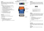
Power Input Connector (J3)
PAC-5070 uses +9VDC to 40VDC power and input from J3
connector. Auto-polarity and surge protection are included
in power input circuitry of PAC-5070 to provide power protection to PAC-5070.
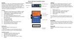
Digital Input Connector
The 8 channel isolated input are equipped with 2500 Vrms
photo coupler isolator. Four of the channels form a group
and share the same common ground. The specification of the
isolated input channels are:
Analog Input Connector
Each of the 4 channels isolated analog input can be configured
as various input range and the common features are show as
follow:
Effective Resolution: 16-bit
Channels: four differential input channels
Input Type: mV, V, mA
Input Range:
Uni-polar:0~150mV, 0~500mV, 0~1V, 0~5V, 0~10V
Bi-polar: +/- 150mV, +/- 500mV, +/- 1V, +/- 5V, +/- 10V
Current: 0~20mA
Sampling rate: 10~100 samples /sec
Input Impedance: 20 M Ohm
Accuracy: +/- 0.1%
CMR: 50/60 Hz 100dB
Isolation: 1500Vrms (Three-way)
Logical High: 5~24Vdc
Logical Low: 0~1.5Vdc
Input resistance: 1.2KOhms @0.5W
Response time: 20us
Isolation: 2500Vrms
+ -
Digital Output Connector
The digital output are equipped with 8 darlington pair transistors (Allegro UDN2981A) to switch the external relay or solenoid. The internal transient-suppression diodes permit the
drive to be used with inductive load. The source voltage of
the drive is from 5Vdc to 40 Vdc and the maximum driving
current is 500 mA.
DI1~4
Each of the analog input channel provides (+) (-) and AGND
input. To measure floating source such as battery (+,-) and single-ended output which provides positive (+) and ground signal,
please connect the negative or ground of the signal to AGND pin
in order to provide a virtual ground reference.
To measure current input, please set the jumper (JP1~JP4) to
current setting as show below:
COM1
DIx: Isolated digital input channels
COMx: common ground of four DIx
VS
Power
5~40Vdc
Input Type Selection Jumper JP1~JP3
1
3
Voltage Input: 1-2 (default)
Current Input: 2-3
DO1~8
V/A
+
_
120 Ω
PGA
GND
DOx: Voltage output channels
GND: Ground
VS: Voltage source input
Relay
DC
AGND
DC
AD