1
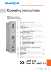
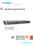
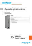
Professional Headend Solutions
Operating instructions
Headend Controller
Headend control unit with 8A power supply
Contents
1. Safety and operating instructions.................................................................... 2
2. Device variants.................................................................................................. 2
3. General ............................................................................................................. 2
4. Front view.......................................................................................................... 3
5. Functional description ...................................................................................... 3
6. Head end bus structure.................................................................................... 3
6.1 Minimum configuration (without Bus Extender) ....................................... 3
6.2 Standard configuration (with Bus Extender) ............................................ 4
7. Head end bus structure.................................................................................... 4
8. Redundancy circuit........................................................................................... 4
9. Alarm function .................................................................................................. 5
10. Technical data ................................................................................................ 5
11. Programming ................................................................................................. 6
10.1 Main program ......................................................................................... 6
10.2 Adjustments ............................................................................................ 6
10.3 Subroutine “Change configuration“........................................................ 7
10.4 Adjusting of the IP number ..................................................................... 7
11. Bibliography ................................................................................................... 8
12. Document history ........................................................................................... 9
HCB x00
Part No: 965x.0x
HCB
x00
Part N : 965x.0x
Headend Controller
Headend control unit with 8A power supply
o
B
LINE
1. Safety and operating instructions
When assembling, starting-up and adjusting the modules, it is necessary to consider the system specific
references in the manual instruction!
The modules may only be installed and started up by authorized technical personnel!
When assembling the modules into the receiving points, the adherence of the EMC regulations is to be secured!
The assembly and wiring have to be done without voltage!
All active modules may only be operated with the Headend Controller HCB x00 or Bus Extender BEB x00!
The main voltage and the operating voltage of the modules working by DC have to be in complience to the operating
parameters described in the technical data.
With all work the defaults of the DIN EN 50083 have to be considered! Especially the safetyrelevant execution of the
DIN EN 60728-11 [1] is necessary!
2. Device variants
HCB 200 HCB 300 HCB 300 9652.01 Headend control unit with 8A power supply (100 ... 240 V~ input)
9653.01 Headend control unit with 8A power supply (48 V– input)
9653.02 Headend control unit with 8A power supply (48 V– input)
3. General
The Headend Controller HCB x00 is a module of the head end system B-LINE, which can also be used in the head end system
C-LINE/ C-LINE+ .
The B-LINE system is conceived as a complete system for middle sized distribution networks, the C-LINE/ C-LINE+ for smaller
distribution networks. All active modules are programmed via the central Headend Controller.
The individual modules will be addressed by the address switch at the Bus Extender (line) (BEB x00) and at the respective module
(position).
The status of the modules will be displayed by colored LEDs:
· Red - ERROR Control bus error
· Green - READY Operating status
· Yellow - DATA Data traffic at the internal control bus
RJ 45 socket:
· Yellow - DATA · Blue - LINK Data traffic (LAN/ WAN)
Connection
2
HCB
x00
Part N : 965x.0x
B
Headend Controller
Headend control unit with 8A power supply
o
LINE
4. Front view
HCB 200
HCB 300
3
9653.02
INPUT VOLTAGE (DC) 36 ... 72 V
INPUT POWER
max. 110 W
ALARM SOURCE
yes
ADDRESSING SPACE max. 240 UNITS
OUTPUT (DC)
12 V, max. 8 A
Display
HEADEND CONTROLLER
HEADEND
CONTROLLER
POWER SUPPLY
POWER
SUPPLY
Type: HCB 200
Part No.: 9652.01
INPUT VOLTAGE (AC)
INPUT VOLTAGE
INPUT FREQUENCY
INPUT FREQUENCY
INPUT POWER
INPUT POWER
ALARM
ALARM SOURCE
SOURCE
OUTPUT
OUTPUT (DC)
(DC)
HEADEND CONTROLLER
POWER SUPPLY
Type: HCB 300 Part No.: 9653.02
Control keys
Reset key
Type: HCB 200 Part No.: 9652.01
100 ... 240V
100 ... 240 V
50/ 60
Hz
50 / 60 Hz
max. 110 W
max. 110 W
yes yes
12 V,12 V / max.
max. 88A
A
INPUT VOLTAGE (DC)
INPUT POWER
ALARM SOURCE
ADDRESSING SPACE
OUTPUT (DC)
36 ... 72
max. 110
max. 240
12 V, V
W
yes
UNITS
max. 8A
Operating voltage/
control bus (X1, X2)
LED “ERROR“ (red)
LED “READY“ (green)
LED “DATA“ (yellow)
LAN/ WAN
LED “DATA“ (yellow)
LED “LINK“ (blue)
+
-
DC
INPUT
Power supply
48 V- / max. 3.3 A
+ -
5. Functional description
The Headend Controller HCB x00 is the central control module of the head end or the individual switch cabinet. It consists the data
interfaces to a PC/ LAN/ WAN and to the Bus Extender (BEB x00). The head end internal data bus has to be connected as seen in
chapter 6 to 8 and the alarm function is descriped in chapter 9. Both bus connections X1 and X2 can be used for that. The data interface to a PC/ LAN/ WAN is implemented as a IP-/ Ethernet interface (RJ 45). Programming can be done but also directly at the control
unit (see programming). By pressing the reset-key the HCB x00 reboots and all data of the head end are read out again.
The internal power unit supplies the control unit and in case of a Bus Extender (BEB x00) error it will switch automatically to the
respective line. The Headend Controller HCB 200 and HCB 300 (9653.02) have an integrated current display, but the HCB 300
(9653.01) hasn‘t this function. It is recommended to use an individual control unit for every circuit (switch cabinet).
The IP address of each control unit can be edited and adapted to the respective LAN.
Additional information: Redundancy circuit (Headend Controller)
Structure (minimum configuration)
Option: SNMP and DHCP
(chapter 8)
(chapter 6)
6. Head end bus structure
Module
ADDR. 15
Module
ADDR. 01
.
HCB x00
Module
ADDR. 00
6.1 Minimum configuration (without Bus Extender)
HCB x00
Headend Contoller
The number of the possible module connections (00 ... 15) to a
BEB x00 depends on the total power consumption of this line!
3
HCB
x00
Part N : 965x.0x
o
Headend Controller
Headend control unit with 8A power supply
B
LINE
Module
ADDR. 15
Module
ADDR. 15
Module
ADDR. 15
Module
ADDR. 01
BEB x00
ADDR. 01
Module
ADDR. 01
Module
signal processing
unit
Module
ADDR. 01
BEB x00
Bus Extender
BEB x00
ADDR. 02
HCB x00
Headend
Controller
BEB x00
ADDR. 15
HCB x00
6.2 Standard configuration (with Bus Extender)
The number of the possible module connections (01 ... 15) to a
BEB x00 depends on the total power consumption of this line!
7. Redundancy circuit
Module
ADDR. 15
Module
ADDR. 15
Module
ADDR. 15
Module
ADDR. 01
Module
ADDR. 01
BEB x00
ADDR. 01
Module
ADDR. 01
broken
BEB x00
ADDR. 02
redundancy
supply
BEB x00
ADDR. 15
HCB x00
(Power supply redundancy)
Description of the power supply redundancy
With the redundant operation of a system, the control unit HCB x00 will automatically take over the function of the power supply, if the
Bus Extender BEB x00 is failing .
4
HCB
x00
Part N : 965x.0x
o
B
Headend Controller
Headend control unit with 8A power supply
LINE
8. Alarm function
To activate the alarm function is additional hardware 9651.01 or 9651.02 necessary!
The device is endorsed by an additional alarm function and current limitations, voltage drops and communication disturbaces. The
contact 13 in the communication and supply bus is switched (+5V to 0 V) in case of alarm.
The alarm modules are available in 1 RU and in panel form. It is possible to insert the modules in any order into bus system. The signal is fed to a SUB-D 9 connector via relais in case of alarm. All the contacts are galvanically isolated. It is possible to trigger several
kinds of alarm.
9. Technical data
Manual operation
Input
Display 3 operating keys,
reset key
LCD, lit
19 x 28 mm
Remote control
Network connection (LAN/ WAN) Input connection Ethernet, 10 Base T
RJ 45
Address extent
Without Bus Extender With Bus Extender 16 modules
240 modules
(15 x 16)
Power supply HCB 200
Mains voltage Voltage frequency Mains connector Internal device fuse Power consumption Output DC voltage Rippled noise ratio Current drain Current limit Short circuit protection Overvoltage protection
Protective system Protection class Radio noise suppression Temperature range
100 ... 240 V (+10%/ -5%)
47 Hz … 63 Hz
built in connector
EN 60320-1/ C8
(IEC 320 C8) [3]
G 5 x 20, T4A
(IEC 127 - 2/ V)
max. 110 W
12 V
66 dB
max. 8 A**
yes (9 A typical)
yes
yes (≤ 14,5 V)*
II acc.. DIN VDE 0860 [4]
IP 20
according DIN VDE 0871
(curve B) [5]
-10 … +55°C
Power supply HCB 300 (9653.01)
Input voltage
Input current (at 48 V)
Power consumption
Overcurrent protection
Overvoltage protection
Max. current drain Voltage stability Radio noise suppression
48 V DC (36 ... 72 V DC)
2.4 A
max. 125 W
fold back
(at 110 ... 143% IOUT)
16.8 ... 20 V
8 A (-10 ... +43 ˚C)**
6 A (+55 ˚C)
1500 V DC (input/ output)
EN 55022 (CIS PR22) Class B [6]
EN 61000-4-2,3,4,6,8 [7] /
ENV 50204 [8]
Power supply HCB 300 (9653.02)
Input voltage
Input connection 48 V DC (36 ... 72 V DC)
Plug with screw termina-
tion, with polarity protec-
tion
Fuse
Polarity reversal protection
Power consumption Voltage stability AC
Output DC voltage Rippled noise ratio Output current Current limit Short circuit protection Overvoltage protection
Protection class Noise emission Immunity
Temperature range T 6.3 A/ 250 V “H“ (5x20, internal“)
yes
max. 110 W
1500 V (input/ output)
12 V
66 dB
0.25 ... 8 A
yes
yes, hicc-up mode
yes (> 14.5 V)
IP 20
EN 55011 [9], EN 55022 (CIS PR22) Class B [6],
EN 50083-2 [2]
EN 61000-6-1 [10]/
EN 61000-6-2 [11]
-10 … +60 °C
Environmental conditions
Relative humidity Mounting method Mounting location ≤ 80 % (non condensing)
vertical
splash-proof and
drip-proof
Physical information
Dimensions (l x w x h)
without 19“-adapter with 19”-adapter Weight HCB 200, 300 (9653.02)
HCB 300 (9653.01)
50 x 276 x 148 mm
50 x 301 x 148 mm
about 1,500 g
about 1,600 g
Delivery contents
1 x Power cord or connector
1 x Screw driver
2 x Wrenches
4 x Terminal resistance 75 Ω
2 x Multipole sockets
Software options
SNMP activation *
to reset device 2 minutes without voltage!
> 6 A only use bus cable “8 A“ !
**
5
CKB 100 (9650.50)
HCB
x00
Part N : 965x.0x
B
Headend Controller
Headend control unit with 8A power supply
o
LINE
10. Programming
10.1 Main program
BLANKOM
ENTER
Address selection
Selection modules
abort
Type/ article number
OK
Change module
(see operating instructions of the module)
NIT distribute
any
key
display
distribute static NIT
display
temperature
any
key
display
voltage
any
key
display
current
any
key
Temperature
Voltage
Current *
Configuration
Language
Time
System restart
Change configration
display/ selection
german/ english
display/ selection
hours/ minutes
display/ selection
starting time
1
see chapter 11.3
1.1
Contrast
display/ selection
Version
display
Reset
IP number
+/-
any
key
version
System restart
Back
2
2.1
see chapter 11.4
Change IP number
*
ENTER
Going back
Going forward
only available for HCB 200
10.2 Adjustments
Manuel adjustment
•
•
•
•
•
•
•
Adjustment with the PC/ laptop
• An “online connection” after IP-standard and an ethernet
connection at the PC/ laptop is necessary for the remote
programming
• Adjustment of the line/ position addresses at the Bus Extender BEB x00 as well as at the modules
• At the HCB x00 IP-address input (e.g. 192.168.001.001)
• For “direct connection” between a PC and HCB x00 use a
crossed patch cable (RJ 45)
• For connection over a deviation use an uncrossed patch
cable
• HTML-browser start-up and IP-address as target address
input
• If connected correctly the HTML control surface at the PC
will open up and a blue LED (LINK) at the HCB x00 will be
lit up
• All adjustments of the modules are specified at the control
surface
Adjustment of the addresses at the Bus Extender BEB x00
and at the modules
Activation of the data input at the Headend Controller HCB
x00 by pressing the “ENTER”-key
Display/ adjustment of the parameter of the HCB x00 or a
selected module as in chapter 11.1
Activation of the programming modus of each module by
selecting the line (BEB x00) and the module position (01 …
15) at the Headend Controller (HCB x00) → the yellow LED
at the module will be lit up til the beginning of the parameter
adjustment
Adjustment of the parameter at the selected module according to the individual product description
After the programming the data will be transmitted automatically to the modules → the yellow LED on the HCB x00 will
be lit up during the data transfer process
The green LED shows the operating status
Adjustment of removal of write protection
• Removal of write protection by input of “0000” (password)
and “0000” (user)
Default IP Address
• 192.168.2.80
6
HCB
x00
Part N : 965x.0x
o
Headend Controller
Headend control unit with 8A power supply
10.3 Subroutine “Change configuration”
Change configuration
1
1
Address selection
direct input or selection
all characters/ numbers & capital letters only
All characters Back
1.1
10.4 Adjusting of the IP number
Adjusting facilities of IP numbers
xx
xx or
or zz
zz
(see
figure)
(see next
fig. right)
IP number webserver
xx or zz
xx or zz
(see
figure)
(see next
fig. right)
Subnet mask
Gateway address
xx
xx or
or zz
zz
(see
figure)
(see next
fig. right)
DHCP address
xx
xx or
or zz
zz
(see
figure)
(see next
fig. right)
Trap address *
VEA/ EMA IP number
21
* Software option 9650.50
xx
xx or
or zz
zz
(see
figure)
(see next
fig. right)
* Software option 9650.50
7
xx
xx or
or zz
zz
(see
figure)
(see next
fig. right)
B
LINE
HCB
x00
Part N : 965x.0x
Headend Controller
Headend control unit with 8A power supply
o
B
LINE
Subroutine “Change IP number“
2
xx
IP number is displayed
NO
change
YES
4. Byte (MSB)
3. Byte
2. Byte
1. Byte (LSB)
zz
21
11. Bibliography
[1] EN 60728-11: Cable networks for television signals, sound signals and interactive services Part 11: Safety (IEC 60728-11:2005); German version EN 60728-11:2005
[2] EN 50083-2 : Cabled distribution systems for television and sound signals. Electromagnetic compatibility for equipment;
EN 50083-2:2001
[3] EN 60320-1: Appliance couplers for household and similar general purposes Part 1: General requirements
(IEC 60320-1:2001 + A1:2007); German version EN 60320-1:2001 + A1:2007
[4] DIN VDE 0860: Audio, video and similar electronic apparatus, Safety requirements (IEC 60065:2001, modified + A1:2005, modified); German version EN 60065:2002 + A1:2006 + Cor.:2007 + A11:2008
[5] DIN VDE 0871: Radio noise suppression of high frequency units, Determination of limits for industrial, scientific and me-
dical equipment, identical with CISPR 23 :1987
[6] EN 55022: Information technology equipment - Radio disturbance characteristics - Limits and methods of measurement (IEC/CISPR 22:2005, modified + A1:2005); German version EN 55022:2006 + A1:2007
[7] EN 61000-4-2: Electromagnetic compatibility (EMC) - Testing and measurement techniques-Electrostatic discharge immunity test, 2009-05-31
EN 61000-4-3: Electromagnetic compatibility (EMC) - Part 4-3 : Testing and measurement techniques - Radiated, radio-
frequency, electromagnetic field immunity test (IEC 61000-4-3:2006 + A1:2007); German version EN 61000-4-3:2006 + A1:2008
EN 61000-4-4: Electromagnetic compatibility (EMC) - Part 4-4: Testing and measurement techniques - Electrical fast transient/burst immunity test (IEC 61000-4-4:2004); German version EN 61000-4-4:2004
EN 61000-4-6: Electromagnetic compatibility (EMC) - Part 4-6: Testing and measurement techniques - Immunity to con-
ducted disturbances, induced by radio-frequency fields (IEC 61000-4-6:2003 + A1:2004 + A2:2006)
EN 61000-4-8: Electromagnetic compatibility (EMC) - Part 4-8: Testing and measurement techniques - Power frequency magnetic field immunity test (IEC 77A/694/FDIS:2009); German version FprEN 61000-4-8:2009
[8] ENV 50204: Radiated electromagnetic field from digital radio telephones - Immunity test, 1996-02-15
8
HCB
x00
Part N : 965x.0x
o
B
Headend Controller
Headend control unit with 8A power supply
LINE
[9] EN 55011 : Industrial, scientific and medical equipment Radio-frequency disturbance characteristics – Limits and me-
thods of measurement ; (IEC/CISPR 11:1997, modificated + A1:1999 + A2:2002); German Version EN 55011:1998 + A1:1999 + A2:2002
[10] EN 61000-6-1 : Electromagnetic compatibility (EMC) - Part 6-1: Generic standards - Immunity for residential, commer-
cial and light-industrial environments (IEC 61000-6-1:2005); German version EN 61000-6-1:2007
[11] EN 61000-6-2 : Electromagnetic compatibility (EMC) - Part 6-2: Generic standards - Immunity for industrial environ-
ments (IEC 61000-6-2:2005); German version EN 61000-6-2:2005
12. Document history
Version
Date
Modification
Author
1.00
15.04.2009
basic document
Häußer, Rudolph
1.01
30.07.2009
revision
Häußer
1.02
15.12.2009
revision (program flow)
Häußer
1.03
11.01.2010
insert of HCB 300 (9653.01)
Häußer
1.04
19.01.2011
insert of HCB 300 (9653.02)
Häußer
1.05
22.06.2015
new company
Häußer
Options available upon request! Subjects to changes due to technical progress.
BLANKOM systems GmbH
Hermann-Petersilge-Straße 1 • 07422 Bad Blankenburg • Germany • Phone +49 (0) 3 67 41/ 60-0 • Fax +49 (0) 3 67 41/ 60-100
9
Declaration of Conformity
Manufacturer: BLANKOM systems GmbH
Hermann – Petersilge – Straße 1
07422 Bad Blankenburg
Germany
Product Name: Headend Controller
Type Name: HCB 200, HCB 300
Type No: 9652.01, 9653.01, 9653.02
BLANKOM systems GmbH confirms that the mentioned products meet the guideline(s) of the
Council for the approximation of legislation of the member states.
Electromagnetic compatibility (2004/ 108/ EC)
The following standards are met: DIN EN 50083-2: 2007-04 (EN 50083-2:2006-06)
Low voltage guideline (2006/ 95/ EC)
The following standards are met: DIN EN 60950-1: 2006-04 (EN 60950-1:2006-11)
Information technology equipment -Safety-
Restriction of hazardous substances (2011/ 65/ EC)
The following standards are met: DIN EN 50581: 2013-02 (EN 50581:2012)
Bad Blankenburg, Germany, 2015-06-22
Wolfgang Schlüter
(Managing Director)
10