1
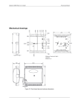
Chapter 4 Specifications All specifications are subject to change without notice. Typical for 25 °C unless otherwise specified. All specifications apply to all temperature and voltage input channels unless otherwise specified. Specifications in italic text are guaranteed by design. Analog input Table 1. General analog input specifications Parameter Conditions A/D converter type A/D data rates Specification ADS1256, 24-bit Sigma Delta 3750 S/s, 2000 S/s, 1000 S/s, 500 S/s, 100 S/s, 60 S/s, 50 S/s, 25 S/s, 10 S/s, 5 S/s, 2.5 S/s Single channel: 2.5 S/s to 1102.94 S/s (software-selectable) Multiple channels: 0.16 S/s to 551.47 S/s (software-selectable) See Table 11 and Table 12 for details. 16 single-ended or 8 differential (software-selectable). Thermocouples require differential mode. For each channel configured as differential, you essentially lose two single-ended channels. 500 VDC min between field wiring and USB interface Temperature sensor input, software-selectable to match sensor type Throughput Number of channels Input isolation Channel configurations Voltage input Input voltage range Absolute maximum input voltage Thermocouple mode ±0.078125 V Voltage mode (Note 1) ±10 V, ±5 V, ±2.5 V, ±1.25 V, ±0.625 V, ±0.3125 V, ±0.15625 V, ±0.078125 V (software-selectable) ±22 V max (power on) ±10 V max (power off) 10 MΩ (power on) 390 Ω (power off) ±20 nA CxH-CxL relative to GND Input impedance Input leakage current Input voltage >±30 V (power on/off) Input capacitance Maximum working voltage (signal + common mode) Common mode rejection ratio (Note 1) ADC resolution Crosstalk Input coupling Channel gain queue Warm-up time Open thermocouple detect Voltage mode Thermocouple mode, (fIN = 60 Hz) Voltage mode, (fIN = 60 Hz, all input ranges) Adj chan, differential mode Up to 64 elements ±1 µA max 590 pf ±10.25 V max 110 dB 90 dB 24 bits 100 dB DC Software-selectable channel and range 45 minutes min Software-selectable for each channel. 20 RedLab 2408-2AO User's Guide Specifications Parameter Conditions Specification CJC sensor accuracy 15 °C to 35 °C 0 °C to 55 °C ±0.5 °C typ ±1.0 °C max Note 1: Placing a notch of the A/D digital filter at 60 Hz (setting A/D data rate = 60 S/s, 10 S/s, 5 S/s or 2.5 S/s) further improves the common mode rejection of this frequency. Channel configurations When any item is changed, the firmware stores channel configurations in the EEPROM of the isolated microcontroller. An external application issues commands over the USB to make changes, and the configuration is made non-volatile through the use of the EEPROM. When connecting differential voltage inputs to a floating voltage source, provide a DC return path from each voltage input to ground. To do this, connect a resistor from each input to an AGND pin. A value of approximately 100 kΩ can be used for most applications. Leave unused input channels either floating or tied to AGND. For each voltage/thermocouple channel configured as differential, you essentially lose one single-ended channel. Keep source impedances as small as possible to avoid settling time and accuracy errors. Table 2. Channel configurations Channel Category Specification CxH/CxL CxH/CxL CxH/CxL Thermocouple Voltage Voltage 8 differential channels 16 individually-configurable channels that can be configured as either single-ended or 8 differential. Compatible sensors Table 3. Compatible sensor type specifications Parameter Conditions Thermocouple J: –210 °C to 1200 °C K: –270 °C to 1372 °C R: –50 °C to 1768 °C S: –50 °C to 1768 °C T: –270 °C to 400 °C N: –270 °C to 1300 °C E: –270 °C to 1000 °C B: 0 °C to 1820 °C Accuracy Thermocouple measurement accuracy Thermocouple measurement accuracy specifications include polynomial linearization error, cold-junction compensation measurement error, and are for sample rates up to 60S/s. These specs are for one year, or 3000 operating hours, whichever comes first. There is a CJC sensor for each terminal block of the module. The accuracy listed below assumes the screw terminals are at the same temperature as the CJC sensor. The accuracy errors shown do not include the inherent accuracy error of the thermocouple sensor itself. Contact your thermocouple supplier for details on the actual thermocouple sensor accuracy limitations. Connect thermocouples to the RedLab 2408-2AO such that they are floating with respect to AGND. When configuring thermocouple sensors, keep any stray capacitance relative to AGND as small as possible to avoid settling time and accuracy errors. 21 RedLab 2408-2AO User's Guide Specifications The AGND and DGND pins are isolated from earth ground. You can connect thermocouple sensors to voltages referenced to earth ground as long as isolation between the AGND/DGND pins and earth ground is maintained. Table 4. Thermocouple accuracy specifications, including CJC measurement error. All specifications are (±). Thermocouple J K N R S B E T Sensor temperature range –210 °C 0 °C 1200 °C –210 °C 0 °C 1372 °C –200 °C 0 °C 1300 °C –50 °C 250 °C 1768 °C –50 °C 250 °C 1768 °C 250 °C 700 °C 1820 °C –200 °C 0 °C 1000 °C –200 °C 0 °C 400 °C Accuracy error, maximum 2.572 °C 0.935 °C 1.869 °C 2.917 °C 1.017 °C 2.478 °C 3.480°C 1.201 °C 1.991 °C 4.826 °C 2.117 °C 2.842 °C 4.510 °C 2.165 °C 3.187 °C 5.489 °C 2.283 °C 2.202 °C 2.413 °C 1.069 °C 1.575 °C 2.821 °C 1.050 °C 0.957 °C Accuracy error, typical 1.416 °C 0.469 °C 1.456 °C 1.699 °C 0.526 °C 2.022 °C 2.030 °C 0.659 °C 1.600 °C 3.133 °C 1.424 °C 2.347 °C 2.930 °Co 1.468 °C 2.597 °C 3.956 °C 1.743 °C 1.842 °C 1.352 °C 0.551 °C 1.211 °C 1.676 °C 0.558 °C 0.595 °C Tempco (°C/°C) 0.022 0.029 0.029 0.082 .089 0.14 0.017 0.027 To achieve the thermocouple accuracies listed above, warm up the RedLab 2408-2AO for 45 minutes after the initial power on. The accuracies listed above are only guaranteed if the device is housed in the plastic enclosure. Analog input DC voltage measurement accuracy Table 5. DC Accuracy components and specifications. All values are (±) Range Gain error (% of reading) Offset error INL error (% of range) Absolute accuracy Gain temperature coefficient (% reading/°C) ±10 V ±5 V ±2.5 V ±1.25 V ±0.625 V ±0.3125 V ±0.15625 V ±0.078125 V 0.0037 0.0047 0.0059 0.0056 0.0068 0.0104 0.0184 0.0384 50 µV 25 µV 20 µV 20 µV 15 µV 15 µV 10 µV 10 µV 0.0008 0.0008 0.0008 0.0008 0.0005 0.0006 0.0005 0.0009 500 µV 300 µV 200 µV 100 µV 60 µV 50 µV 40 µV 40 µV 0.0006 0.0006 0.0006 0.0006 0.0006 0.0006 0.0006 0.0006 22 Offset temperature coefficient (µV/°C) 3 2 1 1 1 1 1 1 RedLab 2408-2AO User's Guide Specifications Input bandwidth Table 6. input bandwidth A/D data rate –3 db Bandwidth (Hz) 3750 S/s 2000 S/s 1000 S/s 500 S/s 100 S/s 60 S/s 50 S/s 25 S/s 10 S/s 5 S/s 2.5 S/s 1615 878 441 221 44.2 26.5 22.1 11.1 4.42 2.21 1.1 Noise performance For the peak-to-peak noise distribution test, a differential input channel is connected to AGND at the input terminal block, and 50,000 samples are acquired at the maximum rate available at each setting. Table 7. Peak-to-peak noise performance specifications (µV) A/D data rate Range 3750 S/s 2000 S/s 1000 S/s 500 S/s 100 S/s 60 S/s 50 S/s 25 S/s 10 S/s 5 S/s 2.5 S/s ±10 V ±5 V ±2.5 V ±1.25 V ±0.625 V ±0.3125 V ±0.15625 V 126.84 56.74 32.96 18.57 18.88 15.33 13.28 100.14 47.56 28.79 17.52 16.58 14.76 16.84 71.76 34.21 17.94 13.83 8.45 8.19 7.47 45.06 25.87 14.19 9.30 7.41 6.94 6.61 30.52 16.21 7.51 5.48 5.32 4.75 5.70 30.52 14.31 7.09 5.48 4.80 4.69 4.48 26.70 14.31 7.09 5.01 4.38 4.49 4.48 19.07 14.30 5.72 3.81 3.86 3.70 4.24 11.92 5.96 3.81 3.34 2.50 3.34 2.66 9.54 4.77 4.00 3.34 2.61 2.56 3.07 9.54 4.77 4.00 2.86 1.98 2.45 2.29 ±0.078125 V 13.47 15.02 9.17 6.88 4.28 4.16 4.00 3.57 2.28 2.13 2.40 Table 8. RMS noise performance specifications (µVRMS) A/D data rate Range 3750 S/s 2000 S/s 1000 S/s 500 S/s 100 S/s 60 S/s 50 S/s 25 S/s 10 S/s 5 S/s 2.5 S/s ±10 V ±5 V ±2.5 V ±1.25 V ±0.625 V ±0.3125 V ±0.15625 V ±0.078125 V 19.22 8.60 4.99 2.81 2.86 2.32 2.01 2.04 15.17 7.21 4.36 2.66 2.51 2.24 2.55 2.28 10.87 5.18 2.72 2.10 1.28 1.24 1.13 1.39 6.83 3.92 2.15 1.41 1.12 1.05 1.00 1.04 4.62 2.46 1.14 0.83 0.81 0.72 0.86 0.65 4.62 2.17 1.07 0.83 0.73 0.71 0.68 0.63 4.05 2.17 1.07 0.76 0.66 0.68 0.68 0.60 2.89 2.16 0.87 0.58 0.58 0.56 0.64 0.54 1.81 0.90 0.58 0.51 0.38 0.51 0.40 0.35 1.44 0.72 0.60 0.51 0.40 0.39 0.47 0.32 1.44 0.72 0.60 0.43 0.30 0.37 0.35 0.36 Table 9. Noise-free resolution specifications (bits) 23 RedLab 2408-2AO User's Guide Specifications A/D data rate Range 3750 S/s 2000 S/s 1000 S/s 500 S/s 100 S/s 60 S/s 50 S/s 25 S/s 10 S/s 5 S/s 2.5 S/s ±10 V ±5 V ±2.5 V ±1.25 V ±0.625 V ±0.3125 V ±0.15625 V ±0.078125 V 17.2 17.4 17.2 17.0 16.0 15.3 14.5 14.5 17.6 17.6 17.4 17.1 16.2 15.3 14.1 14.3 18.1 18.1 18.1 17.4 17.1 16.2 15.3 15.0 18.7 18.5 18.4 18.0 17.3 16.4 15.5 15.4 19.3 19.2 19.3 18.8 17.8 17.0 15.7 16.1 19.3 19.4 19.4 18.8 18.0 17.0 16.1 16.2 19.5 19.4 19.4 18.9 18.1 17.0 16.1 16.2 20.0 19.4 19.7 19.3 18.3 17.3 16.1 16.4 20.6 20.6 20.3 19.5 18.9 17.5 16.8 17.0 21.0 21.0 20.7 19.5 18.8 17.9 16.9 17.1 21.0 21.0 21.0 19.7 19.2 17.9 17.1 16.9 Channel switching error Table 10. Step response accuracy specifications Accuracy Range 3750 S/s 2000 S/s 1000 S/s 500 S/s 100 S/s 60 S/s 50 S/s 25 S/s 10 S/s 5 S/s 2.5 S/s ±10 V ±5 V ±2.5 V ±1.25 V ±0.625 V ±0.3125 V ±0.15625 V ±0.078125 V 0.0010% 0.0009% 0.0010% 0.0013% 0.0022% 0.0031% 0.0056% 0.0114% 0.0008% 0.0008% 0.0007% 0.0009% 0.0016% 0.0031% 0.0062% 0.0123% 0.0005% 0.0004% 0.0008% 0.0008% 0.0011% 0.0020% 0.0048% 0.0076% 0.0004% 0.0004% 0.0004% 0.0007% 0.0011% 0.0017% 0.0037% 0.0070% 0.0002% 0.0003% 0.0003% 0.0004% 0.0007% 0.0015% 0.0032% 0.0041% 0.0002% 0.0002% 0.0002% 0.0004% 0.0007% 0.0012% 0.0025% 0.0051% 0.0003% 0.0002% 0.0002% 0.0003% 0.0005% 0.0010% 0.0024% 0.0046% 0.0002% 0.0002% 0.0002% 0.0003% 0.0005% 0.0010% 0.0021% 0.0036% 0.0001% 0.0001% 0.0002% 0.0003% 0.0004% 0.0012% 0.0019% 0.0032% 0.0001% 0.0001% 0.0001% 0.0003% 0.0005% 0.0009% 0.0022% 0.0030% 0.0001% 0.0001% 0.0001% 0.0003% 0.0003% 0.0009% 0.0016% 0.0034% Channel switching error is defined as the accuracy that can be expected after one conversion when switching from a channel with a DC input at one extreme of full scale to another channel with a DC input at the other extreme of full scale, expressed in terms of percentage of full scale value. Throughput rate The single channel throughput rate is calculated using this formula: Maximum throughput = 1 1 640 s data rate Table 11. Single channel throughput rate specifications A/D data rate Maximum throughput (Hz) 3750 S/s 2000 S/s 1000 S/s 500 S/s 100 S/s 60 S/s 50 S/s 25 S/s 10 S/s 5 S/s 2.5 S/s 1102.94 877.19 609.76 378.79 93.98 57.78 48.45 24.61 9.94 4.98 2.50 24 RedLab 2408-2AO User's Guide Specifications The multiple-channel throughput rate is calculated using this formula: Maximum throughput = 1 , where n is the number of channels 1 640 μs data rate n Table 12. Multiple-channel throughput rate specifications (Hz) Number of input channels 3750 S/s 2000 S/s 1000 S/s 500 S/s 100 S/s 60 S/s 50 S/s 25 S/s 10 S/s 5 S/s 2.5 S/s 1 2 3 4 5 6 7 8 9 10 11 12 13 14 15 16 1102.94 551.47 367.65 275.74 220.59 183.82 157.56 137.87 122.55 110.29 100.27 91.91 84.84 78.78 73.53 68.93 877.19 438.60 292.40 219.30 175.44 146.20 125.31 109.65 97.47 87.72 79.74 73.10 67.48 62.66 58.48 54.82 609.76 304.88 203.25 152.44 121.95 101.63 87.11 76.22 67.75 60.98 55.43 50.81 46.90 43.55 40.65 38.11 378.79 189.39 126.26 94.70 75.76 63.13 54.11 47.35 42.09 37.88 34.44 31.57 29.14 27.06 25.25 23.67 93.98 46.99 31.33 23.50 18.80 15.66 13.43 11.75 10.44 9.40 8.54 7.83 7.23 6.71 6.27 5.87 57.78 28.89 19.26 14.45 11.56 9.63 8.25 7.22 6.42 5.78 5.25 4.82 4.44 4.13 3.85 3.61 48.45 24.22 16.15 12.11 9.69 8.07 6.92 6.06 5.38 4.84 4.40 4.04 3.73 3.46 3.23 3.03 24.61 12.30 8.20 6.15 4.92 4.10 3.52 3.08 2.73 2.46 2.24 2.05 1.89 1.76 1.64 1.54 9.94 4.97 3.31 2.48 1.99 1.66 1.42 1.24 1.10 0.99 0.90 0.83 0.76 0.71 0.66 0.62 4.98 2.49 1.66 1.25 1.00 0.83 0.71 0.62 0.55 0.50 0.45 0.42 0.38 0.36 0.33 0.31 2.50 1.25 0.83 0.62 0.50 0.42 0.36 0.31 0.28 0.25 0.23 0.21 0.19 0.18 0.17 0.16 Analog voltage output Unused AOUTx output channels should be left disconnected. The RedLab 2408-2AO output voltage level defaults to 0 V whenever the host PC is reset, shut down or suspended, or if a reset command is issued to the device. The outputs may have a transient during startup. The duration of the output transient depends highly on the enumeration process of the host PC. Typically, the output of the RedLab 2408-2AO is stable after two seconds. Table 13. RedLab 2408-2AO analog voltage output specifications Parameter Digital-to-analog converter Number of channels Resolution Output ranges Output transient Conditions Specifications DAC8552 Calibrated Uncalibrated Host PC is reset, powered on, suspended or a reset command is issued to device Initial power on Differential non-linearity Output current Output short-circuit protection 2 16 bits ±10 V ±10.05 V (software-selectable) Duration: 2 s Amplitude: 2 V p-p Duration: 50 ms Amplitude: 5 V peak ±0.25 LSB typ ±1 LSB max ±5.0 mA max Unlimited duration AOUTx pins AOUTx connected to AGND 25 RedLab 2408-2AO User's Guide Parameter Specifications Conditions Specifications Output coupling Power on and reset state Output noise Settling time Slew rate Throughput DC DACs cleared to zero-scale: 0 V, ±50 mV 60 µVrms (BW=1.5 KHz) 75 µS 1.0 V/µs 1000 S/s max, system-dependent, 0.01 S/s min 1000 S/s / #ch max, systemdependent, 0.01 S/s min To rated accuracy, 10 V step Single-channel Multichannel Table 14. Calibrated absolute accuracy specifications Range Accuracy (±LSB) ±10 V 16.0 Table 15. Calibrated absolute accuracy components specifications Range % of reading Offset (±mV) Temp drift (%/°C) Absolute accuracy at FS (±mV) ±10 V ±0.0183 1.831 0.00055 3.661 Table 16. Relative accuracy specifications Range Relative accuracy (±LSB) ±10 V 4.0 typ Analog input/output calibration Table 17. Analog input/output calibration specifications Parameter Specifications Recommended warm-up time Calibration Calibration interval AI calibration reference 45 minutes min Firmware calibration 1 year +10.000 V, ±5 mV max. Actual measured values stored in EEPROM Tempco: 5 ppm/°C max Long term stability: 30 ppm/1000 hours The analog output pin is internally routed to the analog input pin. Each AOUTx output can be independently measured by the onboard A/D converter. Software-selectable AO calibration procedure AOUTx readback Digital input/output Table 18. Digital input specifications Parameter Specifications Number of I/O Configuration 8 channels Each DIO bit can be independently read from (DIN) or written to (DOUT). The DIN bits can be read at any time whether the DOUT is active or tri-stated. 0 to +15 V CMOS (Schmitt trigger) Input voltage range Input type 26 RedLab 2408-2AO User's Guide Specifications Parameter Specifications Input characteristics Maximum input voltage range Pull-up/pull-down configuration 47 kΩ pull-up/pull-down resistor, 28 kΩ series resistor 0 V to +20 V max (power on/off, relative to DGND) (Note 2) All pins pulled up to +5 V via individual 47 kΩ resistors (the J6 shorting block default position is pins 1 and 2). Pull down capability is available by placing the J6 shorting block across pins 2 and 3. 500 port reads or single bit reads per second typ. 1.3 V min, 2.2 V max 1.5 V max, 0.6 V min 0.4 V min, 1.2 V max Transfer rate (software paced) Input high voltage Input low voltage Schmitt trigger hysteresis Note 2: DGND pins are recommended for use with digital input and digital output pins. The DGND and AGND pins are common and are isolated from earth ground. Table 19. Digital output specifications Parameter Specifications Number of I/O Configuration (Note3) 8 channels Each DIO bit can be independently read from (DIN) or written to (DOUT). The DIN bits may be read at any time whether the DOUT is active or tri-stated 47 kΩ pull-up, open drain (DMOS transistor) All pins pulled up to +5 V via individual 47 kΩ resistors (the J6 shorting block default position is pins 1 and 2). Digital output – 500 port writes or single-bit writes per second typ. 0 V to +5 V (no external pull up resistor, internal 47 kΩ pull-up resistors connected to +5 V by default) 0 V to +15 V max (Note 5) +50 V min Output characteristics (Note 4) Pull-up configuration Transfer rate (software paced) Output voltage range Drain to source breakdown voltage Off state leakage current (Note 6) Sink current capability DMOS transistor on-resistance (drain to source) Note 3: Note 4: Note 5: Note 6: 1.0 µA 150 mA max (continuous) per output pin 150 mA max (continuous) for all eight channels 4Ω DGND pins are recommended for use with digital input and digital output pins. The DGND and AGND pins are common and are isolated from earth ground. Each DMOS transistor source pin is internally connected to DGND. The external pull-up is connected to the digital output bit through an external pull-up resistor. Adding an external pull-up resistor connects it in parallel with the internal 47 kΩ pull-up resistor of that particular digital input/output bit. Careful consideration should be made when considering the external pull-up resistor value and the resultant pull-up voltage produced at the load. Does not include the additional leakage current contribution that may occur when using an external pull-up resistor. 27 RedLab 2408-2AO User's Guide Specifications Counter Table 20. CTR specifications Parameter Conditions Specification Pin name Number of channels Resolution Counter type Input type Input source Counter read/writes rates (software paced) Input characteristics CTR0, CTR1 2 channels 32-bits Event counter Schmitt trigger, rising edge triggered CTR0 (pin 44) CTR1 (pin 42) System dependent, 500 reads per second. System dependent, 500 writes per second. 562 kΩ pull-up resistor to +5 V, 10 kΩ series resistor ±15 V max Counter read Counter write Each CTRx input pin Input voltage range Max input voltage range CTR0,CTR1 relative to AGND and DGND (Note 7) Input high voltage Input low voltage Schmitt trigger hysteresis Input bandwidth (–3 dB) Input capacitance Input leakage current Input frequency High pulse width Low pulse width Note 7: ±20 V max (power on/off) 1.3 V min, 2.2 V max 1.5 V max, 0.6 V min 0.4 V min, 1.2 V max 1 MHz 25 pf ±120 nA@5 V, ±1.6 mA@±15 V 1 MHz, max 500 ns, min 500 ns, min DGND pins are recommended for use with counter input pins. The DGND and AGND are common and are isolated from earth ground. Memory Table 21. Memory specifications EEPROM 4096 bytes isolated micro reserved for sensor configuration 256 bytes USB micro for external application use Microcontroller Table 22. Microcontroller specifications Type One high-performance 8-bit RISC microcontroller with USB interface (non-isolated) One high-performance 16-bit RISC microcontroller for measurements (isolated) 28 RedLab 2408-2AO User's Guide Specifications Power Table 23. Power specifications Parameter Conditions Specification Supply current (Note 8) Voltage supervisor limits Quiescent current 4.5 V > Vext or Vext > 5.5 V 4.5 V < Vext < 5.5 V Available at terminal block pin 40 Available at terminal block pin 40 Measurement system to PC 275 mA PWR LED = Off; (power fault) PWR LED = On 4.75 V min to 5.25 V max 10 mA max 500 VDC min +5 V user output voltage range +5 V user output current Isolation Note 8: This is the total quiescent current requirement for the RedLab 2408-2AO which includes up to 10 mA for the status LED. This does not include any potential loading of the digital I/O bits, +5 V user terminal or the AOUTx outputs. USB specifications Table 24. USB specifications Parameter Specifications USB device type Device compatibility USB cable type USB 2.0 (full-speed) USB 1.1, USB 2.0 A-B cable, UL type AWM 2527 or equivalent. (min 24 AWG VBUS/GND, min 28 AWG D+/D–) 3 meters max USB cable length Environmental Table 25. Environmental specifications Parameter Specifications Operating temperature range Storage temperature range Humidity 0 °C to 50 °C max –40 °C to 85 °C max 0 to 90% non-condensing max Mechanical Table 26. Mechanical specifications Parameter Specifications Dimensions (L x W x H) User connection length 127 89.9 35.6 mm (5.00 x 3.53 x 1.40 in.) 3 meters max Screw terminal connector type and pinout Table 27. Screw terminal connector specifications Connector type Wire gauge range Fixed screw terminal 16 AWG to 30 AWG 29 RedLab 2408-2AO User's Guide Specifications Screw terminal pinout Table 28. 8-channel differential mode pinout Pin Signal name Pin description Pin Signal name Pin description 1 CH0H Channel 0 HI 23 AGND Analog ground 2 CH0L Channel 0 LO 24 CH7L Channel 7 LO 3 AGND Analog ground 25 CH7H Channel 7 HI 4 CH1H Channel 1 HI 26 AGND Analog ground 5 CH1L Channel 1 LO 27 CH6L Channel 6 LO 6 AGND Analog ground 28 CH6H Channel 6 HI 7 CH2H Channel 2 HI 29 AGND Analog ground 8 CH2L Channel 2 LO 30 CH5L Channel 5 LO 9 AGND Analog ground 31 CH5H Channel 5 HI 10 CH3H Channel 3 HI 32 AGND Analog ground 11 CH3L Channel 3 LO 33 CH4L Channel 4 LO 12 AGND Analog ground 34 CH4H Channel 4 HI 13 DGND Digital ground 35 AGND Analog ground 14 DIO0 Digital input/output 36 AOUT1 Analog output 1 15 DIO1 Digital input/output 37 AGND Analog ground 16 DIO2 Digital input/output 38 AOUT0 Analog output 0 17 DIO3 Digital input/output 39 CHAS Chassis ground 18 DIO4 Digital input/output 40 +5V +5 V output 19 DIO5 Digital input/output 41 DGND Digital ground 20 DIO6 Digital input/output 42 CTR1 Counter 1 21 DIO7 Digital input/output 43 DGND Digital ground 22 DGND Digital ground 44 CTR0 Counter 0 30 RedLab 2408-2AO User's Guide Specifications Table 29. 16-channel single-ended mode pinout Pin Signal name Pin description Pin Signal name Pin description 1 CH0 Channel 0 23 AGND Analog ground 2 CH8 Channel 8 24 CH15 Channel 15 3 AGND Analog ground 25 CH7 Channel 7 4 CH1 Channel 1 26 AGND Analog ground 5 CH9 Channel 9 27 CH14 Channel 14 6 AGND Analog ground 28 CH6 Channel 6 7 CH2 Channel 2 29 AGND Analog ground 8 CH10 Channel 10 30 CH13 Channel 13 9 AGND Analog ground 31 CH5 Channel 5 10 CH3 Channel 3 32 AGND Analog ground 11 CH11 Channel 11 33 CH12 Channel 12 12 AGND Analog ground 34 CH4 Channel 4 13 DGND Digital ground 35 AGND Analog ground 14 DIO0 Digital input/output 36 AOUT1 Analog output 1 15 DIO1 Digital input/output 37 AGND Analog ground 16 DIO2 Digital input/output 38 AOUT0 Analog output 0 17 DIO3 Digital input/output 39 CHAS Chassis ground 18 DIO4 Digital input/output 40 +5V +5 V output 19 DIO5 Digital input/output 41 DGND Digital ground 20 DIO6 Digital input/output 42 CTR1 Counter 1 21 DIO7 Digital input/output 43 DGND Digital ground 22 DGND Digital ground 44 CTR0 Counter 0 . 31 Meilhaus Electronic GmbH Am Sonnenlicht 2 82239 Alling, Germany Phone: +49 (0)8141 5271-0 Fax: +49 (0)8141 5271-129 E-Mail: [email protected] http://www.meilhaus.com