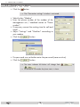
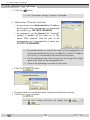
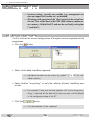
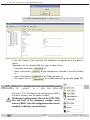
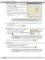
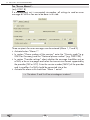
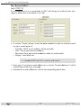
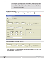
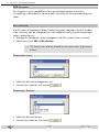
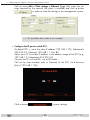
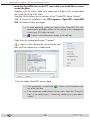
Download Operating Instructions
Transcript
Control and Remote Control Software CCRS 1000 V.43 for head-end station system CSE 3300 Art. Nr. 325182 GB Operating Instructions TRIAX - your ultimate connection Contents 1 Software License Agreement......................................................................... 5 1.0 Software License Agreement......................................................5 1.1 Definitions...............................................................................5 1.2 Software License.......................................................................5 1.3 Obligations and Restrictions.......................................................6 1.4 Transfer...................................................................................6 1.5 Intellectual Property Ownership, Reservation of Rights...................6 1.6 No Warranty...........................................................................6 1.7 Limitation of Liability..................................................................6 1.8 General Provisions....................................................................7 1.9 Compliance with Licenses..........................................................7 2 General information..................................................................................... 8 2.1 Packing contents.............................................................................8 2.2 Meaning of the used symbols...........................................................8 2.3 Description....................................................................................9 2.4 PC system requirements...................................................................9 2.5 Required Hardware......................................................................10 3 Installing the software on a PC.................................................................... 11 3.1 Key Code (Activation Code) for the software....................................11 3.2 Installing the software....................................................................11 4 Basic configuration of the plant................................................................... 13 4.1 In situ operation (Direct connection)................................................13 4.2 Remote control via modem without management system....................14 4.3 Remote control via management system...........................................14 5 Connection to the plant............................................................................... 15 5.1 Requirements...............................................................................15 5.2 Connection via COM port (in situ connection)..................................16 5.3 Connection via Modem.................................................................17 5.4 Connection via Ethernet.................................................................18 6 Controlling the plant................................................................................... 19 6.1 Read data (configuration)..............................................................19 6.2 Menu File – Administrate the configuration data...............................20 New plant...................................................................................21 Open plant.............................................................................21 Save plant..............................................................................22 Save plant as….......................................................................22 Close plant..................................................................................22 - 2 - CCRS 1000 6.3 6.4 Print plant...............................................................................23 Export.........................................................................................24 Exit.............................................................................................24 Menu Plant – Communication programme <–> plant.........................24 Read data...............................................................................25 Send data...............................................................................26 Control unit.............................................................................27 Reset...........................................................................................27 Activate ( ) / Deactivate ( ) connection..............................28 Menu Edit – Plant configuration......................................................28 Data settings...........................................................................28 Example:................................................................................29 Section Input Line A/B:............................................................30 Section Output Line A/B:..........................................................30 Section Output "Line ASI":........................................................31 Create NIT (Network Information Table)......................................32 "Logical Channel Number - LCN":.............................................33 Save the NIT...........................................................................37 Edit NIT (Network Information Table)...............................................38 Section "From" > cassette:........................................................39 Section "From" > All:...............................................................39 Section "From" > New:............................................................40 Section "From" > Import:..........................................................40 Section "From" > Headline:......................................................41 Section "New":.......................................................................42 Section "To":...........................................................................43 Export:...................................................................................44 Copy NIT....................................................................................45 Timer......................................................................................47 Define a timing circuit:.............................................................47 Define a new timer:.................................................................48 Edit a timer:............................................................................48 Delete timer:...........................................................................48 Sort timer:..............................................................................49 Spectrum I/Q...............................................................................50 MTP Function..........................................................................51 Section "Routing":...................................................................52 Section "Input":.......................................................................52 Section "Output":....................................................................55 Toolbar:.................................................................................55 Logbook............................................................................56 Data rate measurement.......................................................57 - 3 - CCRS 1000 Reset filter settings ("Clear Output list")..................................57 Read stream information......................................................58 Add a new PID...................................................................59 Remap a PID......................................................................59 Plant settings................................................................................60 Station data:...........................................................................61 Tab "Password":......................................................................61 Tab "Modem":........................................................................62 Tab "Ethernet":........................................................................62 Tabs for the Alarm settings:.......................................................64 Tab "Alarm settings":...............................................................64 Tab "Alarm Modem":...............................................................65 Tab "Alarm E-Mail":.................................................................66 Tab "Alarm SNMP-Traps":........................................................67 Monitoring cassette.......................................................................68 Change transmitter.............................................................69 Insert transmitter from head station........................................69 New transmitter..................................................................70 Delete transmitter................................................................70 Reference level...................................................................70 Switching on ( ) and off ( ) the transmitter control individually:.70 Cassette settings.................................................................71 Cassette settings – section "Output": .........................................71 Cassette settings – section "Video":...........................................72 Cassette settings – section "Level tolerance settings":....................73 Cassette settings – section "Attenuation setting":..........................73 Cassette settings – section "Display Text":...................................73 Backup System.............................................................................74 Input assignment:.....................................................................74 Backup System: Output............................................................75 Backup System: Input...............................................................75 MTP Program...............................................................................76 Edit selection................................................................................76 Component plant:....................................................................76 Component Station:.................................................................76 Component Cassette:...............................................................77 6.5 Menu Options..............................................................................78 Monitoring cassette.......................................................................78 Level indication:......................................................................78 Start search run:......................................................................79 Management unit.........................................................................79 Test alarm report:....................................................................79 - 4 - CCRS 1000 Timer..........................................................................................80 Time offset:.............................................................................80 Restart Timer:..........................................................................81 Key.............................................................................................82 IPS1............................................................................................82 6.6 Menu Language...........................................................................82 6.7 Menu Help..................................................................................82 6.8 Station configuration................................................................83 7 Final Hints.................................................................................................. 84 Annex A......................................................................................................... 85 A1 Connection PC Ethernet UMTS-VPN Management system.. 85 Sample configuration with tested components..................................85 Components used....................................................................86 Functional principle.................................................................86 Configuration sequence...........................................................87 8 Index......................................................................................................... 96 - 5 - CCRS 1000 1 Software License Agreement This document includes warranty information and a license agreement governing the use of TRIAX A/S software. 1.0 S o f t wa r e L i c e n s e A g r e e m e n t By using, copying or distributing the TRIAX software, you accept all the terms and conditions of this agreement, including, in particular, the provisions on: – Use contained in section 1.2; – Transferability in section 1.4; – Warranty in section 1.6 and liability in section 1.7. Upon acceptance, this agreement is enforceable against you and any entity that obtained the software and on whose behalf it is used. If you do not agree, do not use the software. TRIAX permits you to use the software only in accordance with the terms of this agreement. 1.1 D e f i n i t i o n s "TRIAX" means TRIAX A/S, Björnkärvej 3, 8783 Hornsyld, Dänemark. "Computer" means a virtual or physical personal electronic device that accepts information in digital or similar form and manipulates it for a specific result based on a sequence of instructions. "Software" means all of the contents of the files (delivered electronically or on physical media), or CD or other media with which this agreement is provided, which may include TRIAX or third party computer information or software, including TRIAX "CCRS 1000" and TRIAX "BE-Flash"; related explanatory written materials or files ("Documentation"); and upgrades, modified versions, updates, additions, and copies of the foregoing, provided to you by TRIAX at any time (collectively, "Updates"). "Use" means to access, install, download, copy, or otherwise benefit from using the functionality of the Software. 1.0 SOFTWARE LICENSE AGREEMENT 1.2 S o f t wa r e L i c e n s e If you obtained the Software from TRIAX or one of its authorized licensees, and subject to your compliance with the terms of this agreement, including the restrictions in Section 1.3, TRIAX grants to you a non-exclusive license to use the Software in the manner and for the purposes described in the Documentation as follows: 1.2.1 General Use You may install and use one copy of the Software on your compatible Computer. See Section 1.3 for important restrictions on the use of the Software. 1.2.2 Server Use This agreement does not permit you to install or use the software on a computer file server. 1.2.3 Distribution This license does not grant you the right to sublicense or distribute the Software. 1.2.4 Backup Copy You may make one backup copy of the Software, provided your backup copy is not installed or used. You may not transfer the rights to a backup copy unless you transfer all rights in the Software as provided under Section 1.4. - 6 - CCRS 1000 1.3 O b l i gat i o n s 1.3.1 Notices Any copy of the Software that you make must contain the same copyright and other proprietary notices that appear on or in the Software. 1.3.2 No Modification or Reverse Engineering You may not modify, adapt, translate or create derivative works based upon the Software. You will not reverse engineer, decompile, disassemble or otherwise attempt to discover the source code of the Software except to the extent you may be expressly permitted to reverse engineer or decompile under applicable law. 1.4 T r a n s f e r You may not rent, lease, sublicense, assign or transfer your rights in the Software, or authorize all or any portion of the Software to be copied onto another user’s Computer except as may be expressly permitted by this agreement. You may, however, transfer all your rights to use the Software to another person or legal entity provided that: – you also transfer this agreement, and the Software and all other software or hardware bundled or pre-installed with the Software, including all copies, updates and prior versions, to such person or entity, – you retain no copies, including backups and copies stored on a Computer, and – the receiving party accepts the terms and conditions of this agreement and any other terms and conditions upon which you obtained a valid license to the Software. Notwithstanding the foregoing, you may not transfer education, pre-release, or not for resale copies of the Software. and Restrictions 1.5 I n t e ll e c t ua l P r o p e r t y O w n e r s h i p, R e s e rvat i o n The Software and any authorized copies that you make are the intellectual property of TRIAX. The structure, organization and code of the Software are the valuable trade secrets and confidential information of TRIAX. Except as expressly stated herein, this agreement does not grant you any intellectual property rights in the Software and all rights not expressly granted are reserved by TRIAX. 1.6 N o Wa r r a n t y. The software is being delivered to you "as is" and with all faults. TRIAX and its suppliers do not and cannot warrant the performance or results you may obtain by using the software, certificate authority services or other third party offerings. Except to the extent any warranty, condition, representation or term cannot or may not be excluded or limited by law applicable to you in your jurisdiction, TRIAX and its suppliers make no warranties conditions, representations, or terms (express or implied whether by statute, common law, custom, usage or otherwise) as to any matter including without limitation noninfringement of third party rights, merchantability, integration, satisfactory quality, or fitness for any particular purpose. The provisions of section 1.6 and section 1.7 shall survive the termination of this agreement, howsoever caused, but this shall not imply or create any continued right to use the software after termination of this agreement. 1.7 L i m i tat i o n 1.7.1 In no event will TRIAX or its suppliers be liable to you for any damages, claims or costs whatsoever including any consequential, indirect, incidental damages, or any lost profits or lost savings, even if an TRIAX representative has been advised of the possibility of such loss, damages, or claims. The foregoing limitations and exclusions apply to the extent permitted by applicable law in your jurisdiction. TRIAX’ aggregate liability and that of its suppliers under or in connection with this agreement shall be limited to the amount paid for the software, if any. Nothing contained in this agreement limits TRIAX’ liability to you in the event of death or per- 1.0 SOFTWARE LICENSE AGREEMENT of of Rights L i a b i l i t y. - 7 - CCRS 1000 1.0 SOFTWARE LICENSE AGREEMENT sonal injury resulting from TRIAX’ negligence or for the tort of deceit (fraud). TRIAX is acting on behalf of its suppliers and Certificate Authorities for the purpose of disclaiming, excluding and/ or limiting obligations, warranties and liability as provided in this agreement, but in no other respects and for no other purpose. 1.7.2 Limitation of Liability for Users Residing in Germany and Austria 1.7.2.1 If you obtained the Software in Germany or Austria, and you usually reside in such country, then Section 1.7.1 does not apply, Instead, subject to the provisions in Section 1.7.2.2, TRIAX’ statutory liability for damages shall be limited as follows: – TRIAX shall be liable only up to the amount of damages as typically foreseeable at the time of entering into the license agreement in respect of damages caused by a slightly negligent breach of a material contractual obligation and – TRIAX shall not be liable for damages caused by a slightly negligent breach of a non-material contractual obligation. 1.7.2.2 The aforesaid limitation of liability shall not apply to any mandatory statutory liability, in particular, to liability under the German Product Liability Act, liability for assuming a specific guarantee or liability for culpably caused personal injuries. 1.7.2.3 You are required to take all reasonable measures to avoid and reduce damages, in particular to make back-up copies of the Software and your computer data subject to the provisions of this agreement. 1.8 G e n e r a l P r ov i s i o n s . If any part of this agreement is found void and unenforceable, it will not affect the validity of the balance of this agreement, which shall remain valid and enforceable according to its terms. This agreement shall not prejudice the statutory rights of any party dealing as a consumer. This agreement may only be modified by a writing signed by an authorized officer of TRIAX. Updates may be licensed to you by TRIAX with additional or different terms. This is the entire agreement between TRIAX and you relating to the Software and it supersedes any prior representations, discussions, undertakings, communications or advertising relating to the Software. 1.9 C o m pl i a n c e If you are a business or organization, you agree that upon request from TRIAX or TRIAX’ authorized representative, you will, within thirty (30) days, fully document and certify that use of any and all Software at the time of the request is in conformity with your valid licenses from TRIAX. with Licenses. - 8 - CCRS 1000 2.2 MEANING OF THE USED SYMBOLS 2 General 2.1 Pac k i n g information contents 1 CD (Software CCRS 1000 and assembly instructions) 1 adapter (in order to connect the control unit to a modem) 1 connection cable (RS 232) 2.2 M e a n i n g o f t h e u s e d s ym b o l s Important note —> General note • Performing works —> The shown illustrations of menus are partly dependent on the cassettes resp. its software versions as well as the used operating system and its settings. Variations are possible. - 9 - CCRS 1000 2.4 PC SYSTEM REQUIREMENTS 2.3 D e s c r i p t i o n The CCRS 1000 software allows to configure, record and store the settings of head-end stations / plants of the head-end station system CSE 3300 online as well as off-line. —> All settings (with exception of the "direct control via the virtual control unit") first will be done in the CCRS 1000 software (random access memory – RAM of PC) and must be finally transferred to the plant ("send data")! All current cassettes and head-end stations of the can be controlled with a PC directly via the serial COM port interface of the head-end station, or remote controlled via a modem, a GSM mobile phone or via Ethernet by using a corresponding management system. Software updates: Always keep the software versions of the head-end stations and the CCRS 1000 always up-to-date in order to be able to configure also the newest products. —> The most recent version can be downloaded from "www.triax.com". —> Remote software updates for head-end stations and cassettes can be done with the BEflash software. 2.4 PC s ys t e m r e q u i r e m e n t s System requirements for the CCRS 1000 software: – PC with a Pentium processor, – Windows 95*/98*/ME/2000/XP/Vista/7 (*from Internet Explorer 5 on), – at least 32 MB RAM, at least 50 MB free space on hard drive, – LAN interface (RJ 45 socket, for remote control via Ethernet), – serial interface (RS-232 Sub D, for in situ operation), for PCs with USB connector (without serial interface) use a commercially available USB / RS-232 adapter. – modem (for remote control via phone). – network/internet access for downloads and remote control via internet. - 10 - CCRS 1000 2.5 REQUIRED HARDWARE 2.5 R e q u i r e d H a r dwa r e Only one head-end station can be configured without a management unit. For in situ configuration of the head-end station the PC must be connected to the control unit (RS-232 cable). The head-end station can be remote controlled if a modem is connected to the control unit (BE-Remote) and the modem function is activated in the control unit (see page 15). In order to remote control more than one head-end stations of a plant via the CCRS 1000 software following additional hardware is required (dependent on the kind of connection "router with Internet access" or "modem with phone connection"): – Management system CCRC 2 for remote control via Ethernet of up to two head-end stations or one head-end station + monitoring cassette CCMC 6000 or backup system CCB 16/8, or – management unit CCRC 8 for remote control via Ethernet (requires an additional LAN adapter CCLA) or modem of up to 8 head-end stations, resp. monitoring cassette CCMC 6000 or backup system CCB 16/8. Overview: Remote control via modem Remote control via GSM phone Remote control via LAN (Internet) 2 •) 1 •) 1 — — — • CCRC 8 8 • • • • • •) BE-Remote 1 — — • • • •) CCB 16/8 CCRC 2 CCMC 6000 In situ control via COM port Number of controllable components 2 2 1 ) CCMC or CCB ) requires an additional LAN adapter CCLA 2 - 11 - CCRS 1000 3.2 INSTALLING THE SOFTWARE 3 I n s t a ll i n g the software on a 3.1 K e y C o d e (A c t i vat i o n C o d e ) PC f o r t h e s o f t wa r e A key code is required for the activation of the CCRS 1000 software. 3.2I n s ta ll i n g t h e s o f t wa r e You will find the CCRS 1000 software on the CD attached. • Unzip the "CCRS1000_Vxx.zip" file and start the "setup_CCRS 1000_Vxx.exe" programme by a double click. • Select the desired language and click the OK button to confirm. • When the "Setup-CCRS 1000" menu appears, click the "Next >" button. —> The "License Agreement" window is activated. • Read the license agreement. • If you accept the license agreement select "I accept the agreement" and click the "Next >" button. - 12 - CCRS 1000 3.2 INSTALLING THE SOFTWARE • A table will appear which lists the software versions of the cassettes which are compatible with the CCRS 1000 software. —> Keep the software version of the CCRS 1000 always up-to-date in order to be able to remote control also the newest products. —> After installing the CCRS 1000 software, update the software for the cassettes if necessary. • Click the "Next >" button. • Specify the directory in which the CCRS 1000 should be installed (e.g. C:\Programme\TRIAX\CCRS 1000). • Click the "Next >" button. • Enter a name for the shortcut to the programme which will be created in the start menu. - 13 - CCRS 1000 4.1 IN SITU OPERATION (DIRECT CONNECTION) • Click the "Next >" button. • Click on "Install" in order to proceed with the installation of the programme, or on "Back" to make corrections or changes. 4 Basic 4.1 I n c o n f i g u r a t i o n o f t h e pl a n t s i t u o p e r at i o n (D i r e c t connection) Via direct connection it is possible to control the head-end station more comfortable than via the control unit. In addition the configuration can be stored on the PC. 1 2 • Connect the RS-232 interface 1 on the control unit with the serial interface (e.g. COM 1) on the PC using the supplied cable 2. For PCs without a serial interface, please use a standard USB / RS-232 adapter. - 14 - CCRS 1000 4.3 REMOTE CONTROL VIA MANAGEMENT SYSTEM 4.2 R e m ot e c o n t r o l v i a m o d e m w i t h o u t m a n ag e m e n t s ys t e m Head-end stations can be remotely configured if a PC with a modem is used (alarm messages, timer function and the control of a backup system are not possible). If a GSM modem is selected, the control unit transmits the PIN to the modem. It is also necessary to set the PIN for the SIM card to "0000". 1 Modem +U GND UB PE 3 RS 232 / RS485 Telefon Schalter 123456 1 2 3 4 5 6 ON 2 DIP 4 • Connect the supplied cable 2 to the RS-232 interface on the control unit 1. • Plug the cable 2 into the supplied adapter 3 (make sure they are properly aligned) and tighten the fastening screws. In doing so, observe the labelling on the adapter. • Plug the adapter 3 into the serial interface (RS 232) on the modem and tighten the fastening screws. • Using a standard telephone cable 4, connect the modem to a phone jack (only for analogous modem). • Activate the modem operation via the menu of the control unit for the headend station. —> Therefore observe the assembly instruction of the head-end station. —> Deactivate modem operation (OFF) in order to remote control via a management unit or to control in situ (PC is connected directly). 4.3 R e m ot e c o n t r o l v i a m a n ag e m e n t s ys t e m The basic configuration of the plant depends on the kind of connection (Internet, phone, RS-232) and the management system used. It must be done during the installation of the management system and is therefore described in its assembly instruction. - 15 - CCRS 1000 5.1 REQUIREMENTS 5 Connection 5.1 Requirements The basic configuration of the used management system must already be done during its assembly. t o t h e pl a n t —> Therefore observe the assembly instruction of the management unit. • Start the CCRS 1000 software. —> A key code is required for the activation of the programme. • Click the "OK" button when entered the 25 key code. —> Via menu "Language" select the language of the menus. —> Via menu "Help/Help" you reach the online help (German). Menu "Help/About" shows the software version. - 16 - CCRS 1000 5.2 CONNECTION VIA COM PORT (IN SITU CONNECTION) 5.2 C o n n e c t i o n via COM port (not possible with CCRC 2) • Click the (in situ connection) button. —> The "Connection settings" window is activated. • Select button "Com". —> All in your system existing Com ports are listed. • Select the corresponding Com port. —> You can find the current COM port of an used USB/RS-232 adapter via the Windows system control. • Click the button. —> The status indicator left below will change from . - 17 - to CCRS 1000 5.3 CONNECTION VIA MODEM 5.3 C o n n e c t i o n • Click the via Modem button. —> The "Connection settings" window is activated. • Select button "Modem". • Enter the phone number of the modem of the management unit / head-end station at "Phone number". • If necessary correct the waiting time for call and recall. • Adjust "Settings" and "Qualities" according to your modem. • Click the button. • If a password was set before enter the password (case-sensitive). • Click the button. —> The status indicator left below will change from . —> At connection via modem the phone status is shown. - 18 - to CCRS 1000 5.4 CONNECTION VIA ETHERNET 5.4 C o n n e c t i o n • Click the via Ethernet button. —> The "Connection settings" window is activated. • Select button "Ethernet" and enter – at connection via a local network the IP address and the port of the management unit (separated by a colon) e.g. 192.168.0.120:60002; – at connection via the Internet the "external" (public) IP address of the router or its "dynamic DNS account" and the port of the management unit (separated by a colon) e.g. 212.20.172.000:60002. —> For remote control via Internet the router of the management unit must be connected to the Internet. In addition its "public" IP address with which it is connected to the Internet must be known. —> Port forwarding must be set for the port you set during LAN configuration at the router of the management unit. —> Observe the operating instructions of the router. • Click the button. • If a password was set before enter the password (case-sensitive). • Click the button. —> The status indicator left below will change from . - 19 - to CCRS 1000 6.1 READ DATA (CONFIGURATION) 6 C o n t r o ll i n g t h e pl a n t —> Functions/settings, currently not available (e.g. management unit does not support this function etc.) are disabled. —> All settings (with exception of the "direct control via the virtual control unit") first will be done in the CCRS 1000 software (random access memory – RAM of the PC) and must be sent finally to the plant ("send data")! 6.1 R e a d data ( c o n f i g u r at i o n ) Via this function the current configuration of the plant can be imported into the programme. • Click the button. • Select which data should be imported. —> Individual cassettes can be shown by symbol "+" ( vidual selection. ) for indi- • Select whether "everything", or only the selection (choice) should be overwritten. —> For example: If only one cassette together with "overwriting everything" is selected, all the data of the other cassettes will be deleted in the configuration data of the PC. • Click the button. —> The selected data will be imported. - 20 - CCRS 1000 6.2 MENU FILE – ADMINISTRATE THE CONFIGURATION DATA —> After reading the plant is shown. e.g. … In the left window (tree structure) the hardware configuration of the plant is shown. Dependent on the selected tab the right window shows: – Detailed information ( ) or – basic information ( ) of the components selected in the left window, or – basic information ( ) of all fitted cassettes, or – the supervision list ( ) at installed monitoring cassette (page 69). 6.2 M e n u F i l e – A d m i n i s t r at e t h e c o n f i g u r at i o n data Via menu "File" the data of the configuration held in the main memory can be administrated. All changes/configurations, done in the CCRS 1000, first are held in the temporary random access memory (RAM). Save the configuration data (recommended) so that they can not be lost. - 21 - CCRS 1000 6.2 MENU FILE – ADMINISTRATE THE CONFIGURATION DATA New In this menu you can start a new "empty" configuration. • Select menu item File > New plant. • Confirm the warning with button pl a n t . —> Not saved data are deleted! —> Menu "Plant settings" appears (page 61). Open pl a n t In this menu the saved data of a plant can be loaded into the CCRS 1000. • Select menu item File > Open plant. —> This function can also be selected by button • Select a plant and confirm with button - 22 - . . CCRS 1000 6.2 MENU FILE – ADMINISTRATE THE CONFIGURATION DATA —> In the lower part of the window the "station data" of the plant settings menu are shown. —> The saved data are loaded into the programme (RAM). S av e pl a n t In this menu the current configuration can be saved (backup). • Select menu item File > Save plant. —> This function can also be selected by button . —> The configuration data loaded in the RAM will be saved. —> At new prepared or read data the menu "Save plant as…" appears if a filename is not yet assigned. S av e pl a n t a s … In this menu the current configuration can be saved with a different file name (variant). • Select menu item File > Save plant as… . —> This function can also be selected by button —> The menu "Save plant as…" appears. . • If necessary select a different folder, enter a file name and save the file with button . C los e In this menu the current configuration can be closed. pl a n t —> Not saved data will be lost! • Select menu item File > Close plant. • Close the plant with button . - 23 - CCRS 1000 6.2 MENU FILE – ADMINISTRATE THE CONFIGURATION DATA Print pl a n t In this menu the current configuration can be printed. • Select menu item File > Print plant. —> This function can also be selected by button . —> A "Print preview" window appears. —> In the main section of the window the print preview dependent on the selected settings is shown. • Select all settings to be printed in section "Choice". Select submenu "Address data" via button section "Address data". in In this submenu for example you can enter the address data of the plant. In addition via button " Logo" you can add a bit mapped graphic (".bmp" e.g. a company logo). These address data are printed in the headline. —> Button deletes the logo. • Confirm the address data with button • Start printing with button . . —> Enter the printer setup menu of your PC with button —> The print preview can be cancelled with button - 24 - . . CCRS 1000 6.3 MENU PLANT – COMMUNICATION PROGRAMME <–> PLANT Export In this menu parts of the configuration can be exported as a text file. • Select menu item File > Export. • Select the part to be exported and confirm with button . Enter a file name and the path of the memory location in the appearing "Save as" window in order to store the file. Exit With this menu item you can exit the programme. —> Attention: Unsaved changes will be lost. • Select menu item File > Exit. 6.3 M e n u P l a n t – C o m m u n i c at i o n progr a mme <–> pl a n t The communication with the plant is done via menu "Plant". All settings (with exception of the "direct control via the virtual control unit") first will be done in the CCRS 1000 software (RAM of the PC). In order to get it "active" at the plant the configuration data must be sent finally to the plant ("Send data")! - 25 - CCRS 1000 6.3 MENU PLANT – COMMUNICATION PROGRAMME <–> PLANT Read data In this menu you can read the configuration data out of the plant into the programme (RAM). • Select menu item Plant > Read data. —> This function can also be selected by button . —> If there is no connection to the plant, the menu "Connection settings" appears. For a detailed description of this menu see chapter 5 "Connection to the plant" (page 16). • Select which data of the head-end station should be read. —> Individual cassettes can be shown by symbol "+" ( vidual selection. ) for indi- • Select whether "everything" or only the selection ("choice") should be overwritten. —> For example: If only one cassette together with "overwriting everything" is selected, all the data of the other cassettes will be deleted in the configuration data of the PC. • Click the button. —> The selected data will be imported. - 26 - CCRS 1000 6.3 MENU PLANT – COMMUNICATION PROGRAMME <–> PLANT Send data In this menu you can send the configuration data out of the PC into the plant. • Select menu item Plant > Send data. —> This function can also be selected by button . —> If there is no connection to the plant, the menu "Connection settings" appears. For a detailed description of this menu see chapter 5 "Connection to the plant" (page 16). • Select which data should be sent into the head-end station. —> Individual cassettes can be shown by symbol "+" ( vidual selection. • Click the ) for indi- button. —> The selected data will be sent. - 27 - CCRS 1000 6.3 MENU PLANT – COMMUNICATION PROGRAMME <–> PLANT Control unit In this menu you receive a "virtual" control unit in order to operate the plant via the PC. • Select menu item Plant > Control unit. —> This function can also be selected by button . —> If there is no connection to the plant, the menu "Connection settings" appears. For a detailed description of this menu see chapter 5 "Connection to the plant" (page 16). Via this menu the control unit of the plant can be remote controlled. If several stations are connected select the corresponding control unit in menu "Station". The keys of the figure are designed as buttons (mouse control). In order to activate the system information menu click into the display image. In addition operation via the number keypad of the PC is possible. The assignment of the keys is shown in the figure. Close the menu with menu item Back or button . Reset With this menu item you can restart the plant. • Select menu item Plant > Reset. 7 8 9 4 5 6 1 2 3 —> If there is no connection to the plant, the menu "Connection settings" appears. For a detailed description of this menu see chapter 5 "Connection to the plant" (page 16). —> The number of selectable stations depends on the kind of connection / management unit. • Select the stations to be reset and confirm with button . - 28 - CCRS 1000 6.4 MENU EDIT – PLANT CONFIGURATION A c t i vat e ( ) / D e ac t i vat e ( ) connection With this menu item you can activate/deactivate the connection to the plant (toggle function). • Select menu item Plant > Activate / Deactivate connection. —> This function can also be selected by button / . —> If there is no connection to the plant (menu " Activate connection"), the menu "Connection settings" appears. For a detailed description of this menu see chapter 5 "Connection to the plant" (page 16). —> If there is already an active connection to the plant (menu " Deactivate connection"), the connection will be deactivated. 6.4 M e n u E d i t – P l a n t All necessary tools for configuring the plant are included in menu "Edit": All settings (with exception of the "direct control via the virtual control unit") first will be done in the CCRS 1000 software (random access memory – RAM of the PC). In order not to loose the configuration data it should be saved (recommended). To get it "active" at the plant the configuration data must be sent finally to the plant ("Send data" )! c o n f i g u r at i o n D ata s e t t i n gs Via this menu a component marked in the left window (tree structure) can be configured. • Select the component to be configured in the left window (tree structure). • Select menu item Edit > Data settings. —> This function can also be selected by button (right mouse button). - 29 - or the context menu CCRS 1000 6.4 MENU EDIT – PLANT CONFIGURATION —> If a plant is selected, the menu "Plant settings" appears (see page 61). —> All settings to be done via the control unit are possible. As the settings (and therefore the menus) of the individual cassettes are quite different, cassette CCS-2 1000 is described exemplary in this instruction. —> The changes take effect not until they are sent to the plant . E x a m pl e : —> The function of buttons , "Plant" (page 25), button tion" (page 52). , are described in the main menu is described in menu "Edit > MTP func- In the example the menu contains three submenus (tap - Line A, Line B and Line ASI). In section "Input" of "Line A(B)" all settings for tuner input A(B), in section "Output" all settings for the modulator output A(B) are to be done. "Line ASI" contains all settings for the ASI output. - 30 - CCRS 1000 6.4 MENU EDIT – PLANT CONFIGURATION In the following figures the input fields are assigned to the corresponding menus of the control unit. S e c t i o n I n p u t L i n e A/B: Bx 4 Line A <= LINE => Line B Bx 4A LNB Bx 4A 11836 10600 MHz -0.6 FREQ Bx 4A CN 14 27500 SYMBOL DVB-S In the input fields "Satellite Name" and "Transmitter Name" an optional text (max. 16 character) can be entered. —> This text is shown in listings and facilitates the identification of the transponder set. —> "Names" can only be stored in an existing management system. S e c t i o n O u t p u t L i n e A/B: Bx 4A OUTPUT C67 Bx 4A OUTPUT Bx 4A Filter LEVEL Bx 4A Bx 4A STUFFING NIT => Make Bx 4A 0x0001,0100 Bx 4A QAM 256-QAM SR=6900 (6325) -3 dB on Channel Bx 4A on TS/ONID off Bx 4A normal FAILURE Single Carrier PROGRAM on - 31 - CCRS 1000 6.4 MENU EDIT – PLANT CONFIGURATION S e c t i o n O u t p u t "L i n e ASI": Bx 4 Bx 4 ASI RATE 188 108000 KBits ASI OPTION pos. cont. —> For further information about the settings observe the assembly instruction of the corresponding cassette. Close the menu: • Close the menu via the menu item Back or buttons - 32 - / . CCRS 1000 6.4 MENU EDIT – PLANT CONFIGURATION C r e at e NIT (N e t wo r k I n f o r m at i o n Ta b l e ) Via this menu you can create a new NIT. —> The NIT contains information about the output signals of the plant, which receivers need to do a station search. As most of the receivers cannot work with more than one NIT, all cassettes of a plant must have the same NIT containing all services. This function creates a NIT (including all services) which will be transmitted to all cassettes. • Select menu item Edit > Create NIT. —> This function can also be selected by button (right mouse button). • Click the Do not modify the selection! So it is ensured that all necessary data will be read. • Click the or the context menu button. button. —> The selected data will be read. - 33 - CCRS 1000 6.4 MENU EDIT – PLANT CONFIGURATION – For standard applications leave the check at "Taking nit of original". – For special applications remove the check and enter the specific values. —> Incorrect values may cause malfunctions! —> Via menu Plant > Controlunit or button modifications still can be done at the station (see page 28). That the changes can be considered when the NIT is created you should read in again the station data via the menu Plant > Read data or the button. • Send the NIT to the plant using button . —> NIT is switched to ON at all cassettes. Do not modify the selection! So it is ensured that all necessary data will be sent. • Click the "L o g i c a l C h a n n e l N u m b e r - LCN": LCN is a static, virtual assignment of programme numbers for services. Suitable receivers use these LCN information in order to sort the channels after a station search. The LCN information is part of the Network Information Table (NIT). button. —> At present LCN version 1 is supported. —> As several LCN specifications exist, the settings "Bits for LCN" (10/14) as well as "Private data specifier descriptor" (checkbox/ 00000028/00000029/0000233A) must be done dependent on the receiving end (country specific). - 34 - CCRS 1000 6.4 MENU EDIT – PLANT CONFIGURATION • Click the button in the "Create NIT" menu. —> All services are shown in the table. —> Clicking a column header will change the sorting according to the column criteria. Automatic LCN assignment: • Click the button. —> The LCNs will be assigned in the order of the sorting. Manual LCN assignment: • Click to a service in the table. —> The service is shown in section "LCN assignment" on the right side. • Enter a LCN or (at HD channels) a LCN HD in the corresponding input field and click the button. - 35 - CCRS 1000 6.4 MENU EDIT – PLANT CONFIGURATION —> Due to the differentiation of LCN and LCN HD it is possible to assign the same channel number for a channel transmitted in "SD" and "HD" quality. Suited "HD" receivers will prefer the services in "HD" quality, "SD" receivers will use the service in "SD" quality. —> The assigned LCN is shown in the table on the left side. Visible Service Flag: This setting must be set to "on" if a receiver should find the service during a station search. Setting "off" - for example - is used for channels used for software update only. Reset all LCNs / LCN-HD assignments: • Click at the corresponding button . or —> All assigned LCNs will be deleted in the table. Reset individual LCNs / LCN-HD assignments: • Click to a service in the table. —> The service is shown in section "LCN assignment" on the right side. • Click to the button next to the LCN. —> The assigned LCN will be deleted in the table. Remove individual services: • Click to a service in the table. —> The service is shown in section "LCN assignment" on the right side. • Click to the button. —> The service will be deleted in the table. - 36 - CCRS 1000 6.4 MENU EDIT – PLANT CONFIGURATION Add individual services: In section "LCN assignment" individual services not included in the table can be added via tab "Add service". • Enter the corresponding TS- and ON-ID as well as the SID and the desired LCN (HD). Enter a service name. • Click the button. —> The added service is shown in the table on the left side. Save a LCN list: • Select menu item File > save LCN or click the • Enter file name and location. • Click the button. Export a Service (LCN) list as a text file: • Select menu item Export > Export service list or click the • Enter file name and location. • Click the button. Open a saved LCN list: • Select menu item File > open LCN or click the • Select the corresponding file. • Click the button. button. button. button. —> The current LCN list will be overwritten. Close the LCN menu: • Close the menu via the menu item Back or buttons Send the NIT to the plant: • Send the NIT to the plant with button / . . —> NIT is switched ON at all cassettes. - 37 - CCRS 1000 6.4 MENU EDIT – PLANT CONFIGURATION Do not modify the selection! So it is ensured that all necessary data will be sent. • Click the button. —> Attention: Creating a NIT at the menu of the cassette using the control unit all existing LCNs will be deleted! Close the menu: • Close the menu via the menu item Back or buttons S av e Via this menu the NIT can be saved - LCN settings included. the / . NIT —> Via this function it is possible to save the NIT of a plant in form of an ".oni" file, in order to import it into another plant. • Select menu item File > Save NIT in the "Create NIT" menu. • Enter a file name, select the target directory and save the file using button . —> Via the menu Edit > Copy NIT (page 46) of the CCRS 1000 the saved NIT can be imported into another plant. - 38 - CCRS 1000 6.4 MENU EDIT – PLANT CONFIGURATION E d i t NIT (N e t wo r k I n f o r m at i o n Ta b l e ) Via this menu the NIT can be modified. —> For the majority of all plants it is sufficient to create a NIT "automatically" via menu item "Create NIT". Using menu item "Edit NIT" creates a new NIT "manually". It is e.g. possible to remove transponders from the NIT. These transponders potentially will not be found during station search of receivers. It is also possible to add transponder from "older" cassettes not implied in the NIT automatically. —> Make only modifications if you are aware of its consequences. —> The modifications will be done – as all settings via CCRS 1000 – first in the programme (RAM). The new (modified) NIT must finally be sent to the plant. • Select menu item Edit > Edit NIT. The "Edit NIT" menu consists of three sections: – "From" – herein the contents of the NIT will be selected. – "New" – herein the contents will be collected, modifications are possible. – "To" – herein the targets of the new NIT will be selected. The NIT can be saved in form of an ".oni" file. - 39 - CCRS 1000 6.4 MENU EDIT – PLANT CONFIGURATION S e c t i o n "F r o m " > c a ss e t te: —> All cassettes able to transmit a NIT will be shown. The NIT of a selected cassette will be shown below. • Click to button in order to transfer all listed transponders to section "New", or • select individual transponders in order to transfer only the selection using button to section "New". —>Transponders not transferred to section "New" will not be part of the new NIT and will possibly not found during station search of a receiver! S e c t i o n "F r o m " > A ll : —> The transponder data (not the NIT!) of all cassettes transmitting a NIT will be shown. —> If you would like to check/modify a still modified NIT again, you have to select the NIT via the tap "Cassette"! • Click to button in order to transfer all listed transponders to section "New", or • select individual transponders in order to transfer only the selection using button to section "New". —>Transponders not transferred to section "New" will not be part of the new NIT and will possibly not found during station search of a receiver! - 40 - CCRS 1000 6.4 MENU EDIT – PLANT CONFIGURATION S e c t i o n "F r o m " > N e w : —> Transponders of older cassettes which are not transmitting a NIT and transponders of external components can be added to the NIT manually. As it is not possible to transmit the "new" NIT to external components, the NIT must be switched off at all of this components in order to avoid two different NITs. Older cassettes which are not transmitting a NIT are shown in window "Station Box". • Dependent on the cassette click to the buttons QAM or COFDM and enter the data of the transponder. • Click to button in order to transfer the transponder to section "New". —>The transponder data can be complemented in section "New". —>For adding several transponders repeat this procedure accordingly. S e c t i o n "F r o m " > I m p o r t : • In order to import a saved (exported) NIT click to button . • Click to button in order to transfer all listed transponders to section "New", or • select individual transponders in order to transfer only the selection using button to section "New". —>Transponders not transferred to section "New" will not be part of the new NIT and will possibly not be found during station search of a receiver! - 41 - CCRS 1000 6.4 MENU EDIT – PLANT CONFIGURATION —> This function is useful if a plant e.g consists of four stations, remote controlled via two CCRC 2 management units. In order to create a NIT for the complete plant, first create a NIT for the 2 stations controlled by the 1st CCRC 2. Export this NIT (page 45) and after that import it into the NIT of the both stations of the 2nd CCRC 2. This NIT contains the transponders of all 4 stations. Transmit the NIT into all cassettes of both stations of the 2nd CCRC 2 (page 44). Now this NIT must be exported and after that imported into both stations of the 1st CCRC 2. Now all four stations contain identical NITs. S e c t i o n "F r o m " > H e a dl i n e : In this menu you can modify the "Network ID", the "Version" and the "Network name" (like in menu "Create NIT" page 33). Normally nothing must be modified. • At special applications enter the specific values. —> Incorrect values may result in malfunction! —> Proceed with section "New". - 42 - CCRS 1000 6.4 MENU EDIT – PLANT CONFIGURATION S e c t i o n "N e w ": All transponders selected in section "From" will be listed in the lower part of the window. —> In this section e.g. you can modify transponders, added in section "From > New". • Select a corresponding transponder of the list. —> In the upper part of the window the already entered data are show. • Modify the data of the corresponding transponder if necessary. • Take over the modifications with button into the list. —> In the lower part of the window you see all transponders, contained in the "new" NIT. Via button selected transponders can be removed from the NIT. Via button all transponders can be removed from the NIT. Via button the menu LCN (Logical Channel Numbers) will be opened, to preset "Channel Numbers" (see "Logical channel numbers" page 34). —> Now the "new" NIT is created and can be transmitted to selected cassettes (beware!) or all cassettes (recommended). - 43 - CCRS 1000 6.4 MENU EDIT – PLANT CONFIGURATION S e c t i o n "T o ": All cassettes which can transmit a NIT are listed in the right window. —>In this section you can transfer the "new" NIT, created in section "New" to selected cassettes (beware!) or all cassettes (recommended). • In order to transfer the NIT to all cassettes (recommended) click to button . —>The NIT will be transferred from section "New" to all cassettes. —>Section "New" gets "empty". —>To check the new NIT select a cassette in section "From" –> its NIT is shown. • In order to transfer the NIT to a selection of cassettes (beware!) activate the "target" cassettes in the right window and click to button . —> The NIT will be transferred from section "New" to all activated cassettes. —> Section "New" gets "empty". —> To check the new NIT select a cassette in section "From" –> its NIT is shown. —> The modifications will be done – as all settings via CCRS 1000 – first in the programme (RAM). The new (modified) NIT must finally be sent to the plant. . When the transfer is finished button • With a click on this button it is possible to save the NIT in form of an ".oni" file - LCN settings included. - 44 - is activated. CCRS 1000 6.4 MENU EDIT – PLANT CONFIGURATION • Enter a file name, select the target directory and save the file using button . —> Via the menu Edit > Copy NIT (page 46) of the CCRS 1000 the saved NIT can be imported into another plant. Export: —> This function exports the data shown in section "From". If "Cassette" is selected, the NIT of the selected cassette will be exported. If "All" is selected, the "Output settings" of all cassettes (not the NIT) will be exported. LCN setting will NOT be exported. As there should exist only one NIT per plant, both functions should produce an identical result. • Select menu item Export or click to button • Enter file name and location. • Click the button. Close the menu: • Close the menu via the menu item Back or buttons - 45 - . / . CCRS 1000 6.4 MENU EDIT – PLANT CONFIGURATION C o p y NIT Via this menu a NIT saved in form of an ".oni" file can be imported. • Select menu item Edit > Copy NIT. • Open the selection window using button . • Select the corresponding ".oni" file from the source directory and click on button . • Import the NIT using button . • Confirm the warning with button - 46 - . CCRS 1000 6.4 MENU EDIT – PLANT CONFIGURATION • In order to transfer the NIT to all cassettes (recommended) click to button . —> By default all cassettes able the output a NIT are activated. • In order to transfer the NIT to a selection of cassettes (beware!), deactivate the cassettes which shall not receive the NIT and click to button . —> The NIT will be transferred to all activated cassettes, whose function NIT will be set to "on". - 47 - CCRS 1000 6.4 MENU EDIT – PLANT CONFIGURATION Ti m e r Via this menu the output of analogue cassettes which support this function can be switched on and off - time controlled. —> For this function a management system is required. • Select menu item Edit > Timer. —> This function can also be selected by button or the context menu (right mouse button). —> This function is controlled by the management unit, so any changes must be transferred to the management unit. —> The plant must contain a cassette which can forward the time to the management unit (timing circuit). —> A maximum of 100 timers are possible. Define In the selecting menu "Timing circuit:" all cassettes are shown which can forward the time to the management unit. a t i m i n g c i rc u i t : —> The following cassettes are possible timing circuits: CCS 2370, CCS 1231, CCS 1233, CCS 1234, CCS 1235 • Select the desired timing circuit in the selecting menu with button - 48 - . CCRS 1000 6.4 MENU EDIT – PLANT CONFIGURATION Define • Open the menu "Timer" via Edit > New Timer or button . • Activate (ON) or deactivate (OFF) the timer in section "Timer". • Enter the time and the days the timer is desired. • In section "Output" select, whether the timer should switch on or off the output of the cassette. a n e w ti m er: —> Only one switching operation is possible for each timer. In order to switch a cassette on and off, two timers must be defined. • In section "Station/Box/Line" select the cassette (and the output line A or B), to be switched. • Confirm the timer with button . Edit a ti m er: • Click into the line of the timer to be edited. The corresponding field is activated. • Open the menu "Timer" via Edit > Edit selection or button . —> Alternatively select item "Edit selection" in the context menu (right mouse button). • Edit the settings and confirm the changes with button Delete . ti m er: • Click into the line of the timer to be deleted. The corresponding field is activated. • Delete the timer via menu item Edit > Delete timer or button —> Alternatively select item "Delete timer" in the context menu (right mouse button). - 49 - CCRS 1000 6.4 MENU EDIT – PLANT CONFIGURATION Sort ti m er: With this function the sequence of the timer in the overview can be changed. • Click into the line of the timer to be shifted. The corresponding field is activated. • Shift the timer selected upwards or downwards by menu item Edit > Up / Down or with buttons . —> Alternatively select item "Up / Down" in the context menu (right mouse button). Close the timer menu: • Close the menu via the menu item Back or buttons / . —> This timer function is controlled by the management unit, so any changes must be transferred to the management unit. - 50 - CCRS 1000 6.4 MENU EDIT – PLANT CONFIGURATION S p e c t r u m I/Q Via this menu you can invert the spectral position of the user signal. • Select menu item Edit > Spectrum I/Q. —> This function can also be selected by the context menu (right mouse button). In the menu the lines of all cassettes are listed, possible to set the spectral position. • Via the check boxes select from which lines you would like to change the spectral position (check box marked). • Use button in order to switch the selected lines to spectral position "normal". • Use button in order to switch the selected lines to spectral position "inverse". —> This function is also possible in the output settings of the corresponding cassettes. —> The changes are only effective when they were sent to the plant . Close the menu: • Close the menu via the menu item Back or buttons - 51 - / . CCRS 1000 6.4 MENU EDIT – PLANT CONFIGURATION MTP F u n c t i o n —> The cassette must support this function. As the settings (and therefore the menus) of the individual cassettes are quite different, cassette CCS-2 1000 is described exemplary in this instruction. Via this menu you can set the input and output routing as well as e.g. the filtering of the services and PIDs (dependent on the type of cassette). SIDs and PIDs are shown hexadecimal and decimal. • Select the cassette to be set in the left window (tree structure). • Select menu item Edit > MTP Function. —> This function can also be selected by button (right mouse button). or the context menu Input tuner A Input tuner B Input ASI Internal transport stream 1 - 52 - CCRS 1000 6.4 MENU EDIT – PLANT CONFIGURATION S e c t i o n "R o u t i n g ": In this section the input and output routing can be adjusted. —> Input routing (INROUTE) = the distribution of the input signals to the (internal) transport streams 1 and 2. "A+B+ASI=>1 | ASI=>2" means: Tuner input A + tuner input B + ASI input is switched to internal transport stream 1, in addition the ASI input is switched to internal transport stream 2. • Select the desired setting: e.g. —> Output Routing (OUTROUTE) = the distribution of the (internal) transport streams 1 and 2 and the ASI input to the outputs. "1=>ASI | 2=>MB | ASI=>MA" means: Transport stream 1 is switched to the ASI output, transport stream 2 to modulator B and the ASI input is switched to modulator A. • Select the desired setting: e.g. Via check box the "BAT" and "SDT-other" tables can be filtered out (for both internal transport streams). S e c t i o n "I n p u t ": Via the tabs "Services" and "PIDs" the service and PID filter settings for the (internal) transport streams 1 and 2 can be done. Tab "CA Modul" (transport stream 1) contains the filter settings (the services to be descrambled) and the settings of a CA module. • Select transport stream 1 or 2 via buttons . —> The windows in section "Input" (e.g. A-Pass-Filter) are dependent on the settings of "Input Routing". • In tab "Services" select the services to be transmitted. - 53 - CCRS 1000 6.4 MENU EDIT – PLANT CONFIGURATION —> In order to save bandwidth, PIDs can be deselected (e.g. the PIDs of languages not needed). —> The individual PIDs are arranged below the corresponding channel. In tab "PIDs" all PIDs are listed in ascending order without an assignment to a channel. —> If filters will be activated in tab "Services", these filters are also activated in tab "PIDs" (and vice versa). —> Therefore also observe the functions "Add a new PID " and "Remap a PID " on page 60. —> If filters for Services and PIDs are set, first only the setting of the filters will be transmitted to the cassette. The filters are not activated until the "Filter ON" check box is activated (separately for transport stream 1 and 2 ) and also these settings are transmitted to the cassette . —> Without activated filters all services/PIDs will be transmitted. —> We recommend to perform a cassette reset after a successful transmission - 54 - CCRS 1000 6.4 MENU EDIT – PLANT CONFIGURATION If a cassette contains a CA module, in tab "CA Modul" the corresponding filter settings (the services to be descrambled) as well as the settings of the CA module can be done. • Select the services to be descrambled. —> If a service can not be descrambled, as e.g. the number of PIDs to be descrambled by the CA module are exhausted, PIDs of e.g. not needed languages can be deselected, to get free capacities. Via selection field "Supply" dependent on the cassette (and its software version) the power supply of the CA module can be switched over from 5V to 3.3V. —> Power supply switching of "newer" cassettes will be done automatically. If the cassette does not have the control menu "Supply", Bx 4A Supply CA 5.0 V the selection field "Supply" is out of order. —> Please also observe the operating instructions of the CA module. Via selection field "PIDCheck" the PID monitoring can be switched OFF. —> By default PID monitoring is switched ON. If particular PIDs are not descrambled the CA module is reset. If dropouts occur during the descrambling of several stations the PID monitoring can be switched off. - 55 - CCRS 1000 6.4 MENU EDIT – PLANT CONFIGURATION Configuration of the CA module: —> A connection to the plant must be activated ( • Click on button ). . —> This menu depends on the CA module used. Therefore please observe the operating instruction of the CA module. The following figure is exemplary. —> The menu items are numbered in section "CA Menu". • Click on the corresponding numbered button in section "CA Control" in order to select a menu item. S e c t i o n "O u t p u t ": Herein you get a summery of the selected filters in section "Input" of the corresponding internal transport stream independent on whether the filters are activated. T o o l ba r : The functions of buttons , , and (as well as of the submenu "Plant") are described in main menu "Plant" (page 25), button is described in submenu "Edit > Data settings" (page 29). - 56 - CCRS 1000 6.4 MENU EDIT – PLANT CONFIGURATION Logbook Using this button the log file of the cassette can be shown. • Click on button . —> The cassette must support this function. —> Failures and incidents of the cassette are recorded together with date and time (e.g. missing input signal, reset or remote configuration of the cassette). These incidents are shown in the menu window after read out. —> Saving the configuration will also save the log file. • Click to button in order to read the current log file. —> A connection to the plant must be activated ( ). Otherwise menu "connection settings" appears, in order to activate a connection. • Click to button in order to print the log file. • Click to button in order to export the log file. • Click to button in order to delete the log file in the cassette. - 57 - CCRS 1000 6.4 MENU EDIT – PLANT CONFIGURATION —> A connection to the plant must be activated ( ). Otherwise menu "connection settings" appears, in order to activate a connection. D ata r at e m e a s u r e m e n t Via this function the input and output data rates of cassettes can be displayed. • Activate button . —> The cassette must support this function. —> A connection to the plant must be activated ( ). Otherwise menu "connection settings" appears, in order to activate a connection. —> The data rates are displayed in section "Data Rate Measurement" and will be updated continuously ( is flashing) until is deactivated. —> The data rates of the inputs A, B and ASI are shown. In addition it is possible to read the data rates of the output and the null-packets. In order to get the data rate of a single PID mark the PID in the input window – then its data rate is shown at "PID ?". —> Changes (e.g. of the filter settings) will take effect in measuring not before they are transmitted to the cassette (with activated filters). Reset f i lt e r s e t t i n gs ("C l e a r O u t p u t l i s t ") Via this function the filter settings of the corresponding transport stream 1 or 2 ( ) can be reset. —> The "Filter ON" setting will not be reset!. If you do not set new filter settings after a reset at activated "Filter ON" setting all services are disabled! - 58 - CCRS 1000 6.4 MENU EDIT – PLANT CONFIGURATION Read s t r e a m i n f o r m at i o n Via this function changes in the stream information can be shown. • Activate button . —> A connection to the plant must be activated ( ). Otherwise menu "connection settings" appears, in order to activate a connection. —> is flashing. —> If any changes are registered, is displayed. • Click to button es. in order to show the chang- —> For example an additional PID is shown "underlined". Note that some PIDs will not be transmitted permanently but in intervals of some seconds. This will cause in regular notifications of changes. —> The stream information will be shown until button is deactivated. - 59 - CCRS 1000 6.4 MENU EDIT – PLANT CONFIGURATION A dd a new PID Via this function a new PID can be created. • Click to any PID of the list which should be complemented by the new PID. —> Button becomes "active". • Click to button . • Enter the new PID as a hexadecimal value. —> The new PID will be added to the list at the corresponding position (red type). Remap a PID Via this function a new PID can be remapped. —> The check box of the PID must be deactivated. • Click at the PID to be remapped (e.g. • Click to button . • Enter the new PID as a hexadecimal value. ). —> The "new" PID will be added behind the "old" PID ("old" PID —> "new" PID) . —> The changes are only effective when they were sent to the plant . Close the menu: • Close the menu via the menu item Back or buttons - 60 - / . CCRS 1000 6.4 MENU EDIT – PLANT CONFIGURATION Pl ant Configure a management unit via this menu. s e t t i n gs —> For a connection via COM port (in situ connection) no plant settings are necessary. • Select menu item Edit > Plant settings. —> This function can also be selected by the context menu (right mouse button). - 61 - CCRS 1000 6.4 MENU EDIT – PLANT CONFIGURATION S tat i o n data : • Herein enter data of the plant. —> This data are for information only and will be shown when a saved configuration will be opened in the open dialogue and transmitted in error messages. This helps to keep track if you have to manage several plants. • Select your management unit in drop-down menu "CCRC". —> Dependent on your selection only needed configuration fields are enabled. • Activate the check box beside "CCMC available" if a monitoring cassette is used in your plant. —> Only with this check box activated the settings for error messages are enabled. Ta b "Pa s s wo r d ": Herein you can enter a password for the remote access to the plant if a management unit is selected. —> This password will be asked for when establishing a connection. By default no password is assigned. • Enter your desired password in field "New Password". • Enter your desired password in field "Repeat password" again. • Click to button in order to save the password. —> Using button you can check the password, before you terminate the connection. - 62 - CCRS 1000 6.4 MENU EDIT – PLANT CONFIGURATION Ta b "M o d e m ": If a management unit is connected via modem, the connection settings needed are to be done in this tab. • Select the kind of modem connected to the management unit. If GSM modem (Handy) is selected enter the pin number of its telephone card in field "Pin number". • Select "Direct connection" or "Data recall". At "Direct connection" the plant answers the telephone call. At "Data recall" the plant does not answer the telephone call, but tries to identify the phone number and calls back. Enter the number to be called back in field "Phone number" if an identification of the number does not work. Ta b "E t h e r n e t ": If a management unit is connected via LAN, in section "Settings" all network settings needed are to be done. - 63 - CCRS 1000 6.4 MENU EDIT – PLANT CONFIGURATION —> For connection via Internet (especially for remote maintenance) network knowledge is required. If you are not familiar with the terms in section "Settings" please contact your system administrator. —> The management unit is preset in the factory: CCRC 2 IP: 192.168.0.120 Mask: 255.255.255.0 Port: 60002 Gateway: 192.168.0.1 HTML Port: 80 —> If a different IP address range is used in the network the plant is installed or the preset IP address is already in use, the settings must be changed accordingly. Therefore observe the assembly instruction of the management unit. —> Only use ports in the range of 35000 – 60100 or 61000 – 65000! • Enter the settings required for the network (the plant is installed). • Click to button —> A connection to the plant must be activated ( ). Otherwise menu "connection settings" appears, in order to activate a connection. • Enter the password (default is "TRIAX"). - 64 - CCRS 1000 6.4 MENU EDIT – PLANT CONFIGURATION —> The management unit restarts (ca. 1 minute). The Ethernet password can be changed in section "Enter ethernet password". • Enter the desired password in field "New password" and (for confirmation) in field "Repeat password". • Click to button . —> Like in section "Settings" the modification will be transmitted directly to the management unit. Ta b s for the Alarm s e t t i n gs : The remaining tabs help configuring the alarm messages. Therefore a monitoring cassette CCMC 6000 must be installed. The check box "CCMC available" must be activated in section "Station data". —> Alarm settings can be tested with menu item "Options > Management unit > Test alarm report" (page 80) Ta b "A l a r m s e t t i n gs ": Herein enter the time interval from the appearance of an error until the error message will be sent as well as the language of the error message. - 65 - CCRS 1000 6.4 MENU EDIT – PLANT CONFIGURATION Ta b "A l a r m M o d e m ": (only CCRC 8) If a management unit is connected via modem, all settings to send an error message as SMS or fax are to be done in this tab. Three recipients for error messages can be entered (Alarm 1, 2 and 3). • Activate button "Alarm 1". • In section "Phone number of the receiver" enter the "Country code" (e.g. 0049 for Germany) and the "National phone number" (e.g. 0891234). • In section "Provider settings" select whether the message should be sent as a SMS, a fax or to a pager and select the transmission format supported by the provider (TAP or UCP). Enter the service number (SMSC) of the provider and its qualifier if a SMS should be converted into a fax. • Activate the alarm with check box "Alarm 1 active". —> The alarms 2 and 3 will be set analogous to alarm 1. - 66 - CCRS 1000 6.4 MENU EDIT – PLANT CONFIGURATION Ta b "A l a r m E-M a i l": (only CCRC 2) If a management unit is connected via LAN, all settings to send an error message as e-mail are to be done in this tab. • In section "E-mail settings" enter the data needed in order to send an e-mail via your e-mail account: – Provider: SMTP server address of the provider. – User: Your e-mail account address. – Password: Your password needed in order to send e-mails. – Subject: Individual text —> Standard SMTP port 25 is used to send e-mails. • Enter up to 5 recipient e-mail addresses in section "E-mail addresses" which should receive the error message. • Activate the e-mail addresses via the corresponding check box. - 67 - CCRS 1000 6.4 MENU EDIT – PLANT CONFIGURATION Ta b "A l a r m SNMP-T r a p s ": (only CCRC 2) If a management unit is connected via LAN, all settings to send an error message as SNMP Inform Request are to be done in this tab. Enter up to 3 IP addresses which should receive the error message and activate them via the corresponding check box. —> In case of an error message it will be sent to the activated IP addresses as SNMP Inform Request. See below the structure of the error message: Seq { Int =1; SNMP Version Str =public; Community String Inform { Int =6; RequestId Int =1; Error Int =0; ErrorIndex Seq { Seq { OID =1.3.6.1.4.1.29343.1.0.0.1 Str =Alarm report: 1 Channel in Nuremberg (Tel.: 212.20.172.90:60003) been cancelled } } } } —> The changes are only effective when they were sent to the plant - 68 - CCRS 1000 . 6.4 MENU EDIT – PLANT CONFIGURATION M o n i to r i n g Via this menu a connected monitoring cassette can be configured. Using a monitoring cassette the output signals of a broadband cable system in the frequency range of 47 – 862 MHz can be monitored. Furthermore an info channel is feed into the cable system displaying the channel assignment. The monitoring cassette must be assembled according to its assembly instruction, a channel search must be done. • Read the data of the monitoring cassette . • Select menu item Edit > Monitoring cassette. cassette —> In section "Supervision list" the output signals found during the channel search of the monitoring cassette are shown. Via menu "Edit" channels can be added from a list or manually, changed or deleted. —> Only PAL, FM and DVB-C, but no DVB-T channels can be monitored. - 69 - CCRS 1000 6.4 MENU EDIT – PLANT CONFIGURATION Change tr ansmitter • Select menu item Edit > Change transmitter or click on button . • Activate the transmitter to be changed in the supervision list. • Enter the changes in section "Change". • Take over the modified channels into the "Supervision list" using button . Insert t r a n s m i t t e r f ro m h e a d s tat i o n • Select menu item Edit > Insert from head station or click on button . —> All transmitters of the head-end station are displayed in the "Head station list". • Select all transmitters to be monitored in the "Head station list" and insert them into the "Supervision list" using button . - 70 - CCRS 1000 6.4 MENU EDIT – PLANT CONFIGURATION New tr ansmitter • Select menu item Edit > New transmitter or click on button . • In section "New" enter "Type", "Channel" and the transmitter name. If "Type" is set to "TV digital" the kind of modulation (QAM 4…256) and the symbol rate must be entered. Activate check box "ON" in order to monitor a transmitter. • Insert the transmitter into the "Supervision list" using button . Delete • Activate the transmitter to be deleted in the "Supervision list". • Select menu item Edit > Delete transmitter or click on button . tr ansmitter Reference level In order to monitor level variations first reference levels must be stored. When the data of the monitoring cassette is read ( ) also the current levels of the transmitters are read (column "Level"). • Activate the transmitters in the "Supervision list" whose current levels should be stored for reference levels. • Store the levels of column "Level" for reference via menu item Options > Level–>Reference or click on button . S w itc h i n g on ( ) a n d o ff ( ) th e tr a nsm it te r co ntro l i n d i v i d ua lly : If transmitters are included in the "Supervision list" and reference levels are stored it does not mean that it even will be monitored. The control can be switched on and off individually for each transmitter. • Activate one (or several) transmitter(s) in the "Supervision list". Via menu item Options > Switch control on ( ) or Options > Switch control off ( ) you define which transmitters are to be monitored. In column "Control" of the "Supervision list" these settings are displayed (ON/OFF). - 71 - CCRS 1000 
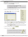
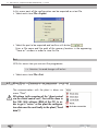
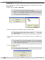
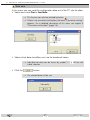
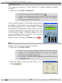
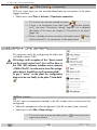
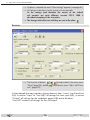
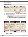
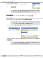
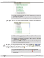
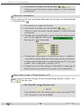
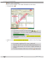
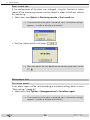
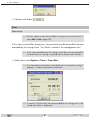
6.4 MENU EDIT – PLANT CONFIGURATION —> Analogue transmitters will be monitored for "level within the tolerance" and "Sync.", digital transmitters for "level within the tolerance", "locked" and "bit error", and FM transmitters for "level" and "malfunction of RDS data". Cassette s e t t i n gs • Select menu item Edit > Cassette settings or click on button Cassette s e t t i n gs – section . "O u t p u t ": • Enter the transmission parameters of the info channel and switch it on or off with check box "Modulator On". - 72 - CCRS 1000 6.4 MENU EDIT – PLANT CONFIGURATION Cassette s e t t i n gs – section "V i d e o ": Modulation "Depth": The modulation depth can be decreased (-5%, -10%) if sound interferences dependent on the picture content occur. Info channel "Infomode": Via this info mode setting the informations to be transmitted can be selected. At display mode "extended" following transmitter data are displayed in the OSD menu "Info channel": Kanal Name BER dBµV – At analogue TV channels: C 2 B R -3 63 C 3 AR D 62 Channel, name and HF level in dBμV. C 4 ZDF 64 – At digital TV channels: 4 2 6 , 0 0 6 , 9 0 0 M s 1 e-7 51 4 3 4 , 0 0 6 , 9 0 0 M s 1 e-7 53 Channel centre frequency in MHz, sym4 4 2 , 0 0 6 , 9 0 0 M s 1 e-7 51 bol rate in MSymbols/second, BER (Bit 9 5 , 1 5 B a yer n 3 62 error rate) and HF level in dBμV. 1 0 4 , 6 0 R a dio F 63 Station 1 S e i t e 1/6 – At FM programmes: Frequency in MHz, RDS name, HF level in dBμV. At display mode "normal" of the Kanal Name OSD menu "Info channel" the HF levels C 2 B R -3 C 3 AR D (dBμV) and the BER (Bit-Error-Rate) are not C 4 ZDF displayed, but the measuring for the moni426, 0 0 6,900 Ms 434, 0 0 6,900 Ms toring is still done in the background. 442, 0 0 6,900 Ms B a yer n 3 95, 1 5 104, 6 0 Station 1 - 73 - R a dio F 6 3 S e i t e 1/6 CCRS 1000 6.4 MENU EDIT – PLANT CONFIGURATION Cassette s e t t i n gs – section "L e v e l to l e r a n c e s e t t i n gs ": • Adjust the level tolerance range of the monitored signals. —> Exceeding the tolerances longer than the time frame set (page 65) results in an error message. Cassette s e t t i n gs – section "A t t e n uat i o n s e t t i n g ": Herein attenuations inserted between the output of the head-end station and the input of the monitoring cassette can be entered in order to take it in consideration for the monitoring (offset). —> Using the measuring output of a CSE 3312, enter the 20dB attenuation of the measuring output, in order to get the actual value of the stations output level. • Enter a corresponding attenuation. Cassette s e t t i n gs – section "D i s pl ay T e x t ": • Enter the text which should be displayed in the footer of the info channel. —> The changes are only effective when they were sent to the plant Close the menu: • Close the menu via the menu item Back or buttons - 74 - / . CCRS 1000 . 6.4 MENU EDIT – PLANT CONFIGURATION B ac k u p S ys t e m Via this menu a connected backup system can be configured. • Select CCB 16/8 in the left window (tree structure) and click to button or… • Select menu item Edit > Backup System. I n p u t • Click to button • Enter the connected satellite layers for the corresponding inputs of the backup system (e.g. astra, astra vl, eutel hl etc.). • Confirm the settings with button . assignment: . - 75 - CCRS 1000 6.4 MENU EDIT – PLANT CONFIGURATION B ac k u p S ys t e m : O u t p u t Herein the present backup cassettes will be entered. • Select the connected backup cassettes for the corresponding outputs of the backup system (e.g. Station 2/Box:1/Linie:A/CCS-2 1001/DVB-S2COFDM). B ac k u p S ys t e m : I n p u t Herein the needed input (SAT layer) will be assigned to the backup cassettes. • In case of a cassettes malfunction assign the needed input to the corresponding backup cassette. —> The changes are only effective when they were sent to the plant Close the menu: • Close the menu via the menu item Back or buttons - 76 - / . CCRS 1000 . 6.4 MENU EDIT – PLANT CONFIGURATION MTP P r o g r a m This function is only needed for a few specific applications/cassettes. Its handling is described in the assembly instruction of the corresponding cassettes. Edit Via this menu a component (plant/station/cassette) selected in the left window (tree structure) can be changed resp. new added virtually (e.g for preconfiguration, planning etc.). • Activate the component to be changed in the left window (tree structure). • Select menu item Edit > Edit selection. selection —> This function can also be selected by the context menu (right mouse button). Component • Select the desired management unit. • Confirm the selection with button C o m p o n e n t S tat i o n : • Select the desired station. • Confirm the selection with button pl a n t : - 77 - . . CCRS 1000 6.4 MENU EDIT – PLANT CONFIGURATION Co m p o n e n t C a ss e t te: • Select the desired cassette. • Confirm the selection with button - 78 - . CCRS 1000 6.5 MENU OPTIONS 6.5 M e n u O p t i o n s Several tools are pooled in menu "Options: M o n i to r i n g Level • Select menu item Options > Monitoring cassette > Level indication. cassette i n d i c at i o n : —> If no connection to the plant is activated, menu "connection settings" appears, in order to activate a connection. • Select a transmitter in the list in order to display its level. —> Indications are level and sync. at analogous transmitters, level and bit error rate (BER) at digital transmitters and the level at FM transmitters. - 79 - CCRS 1000 6.5 MENU OPTIONS S ta r t s e a rc h r u n : If the configuration of the plant was changed, using this function a station search of the monitoring cassette can be started in order to find new stations for monitoring. • Select menu item Options > Monitoring cassette > Start search run. —> If no connection to the plant is activated, menu "connection settings" appears, in order to activate a connection. • Start the station search with button . —> After that read in the new data from the monitoring cassette into the PC . M a n ag e m e n t Te s t A test alarm report will be sent according to the alarm settings done in menu "Plant settings" (page 61). • Select menu item Options > Management unit > Test alarm report. unit al ar m report: —> If no connection to the plant is activated, menu "connection settings" appears, in order to activate a connection. - 80 - CCRS 1000 6.5 MENU OPTIONS • Confirm with button Ti m e r Ti m e . o f fs e t : —> For this option a cassette suitable as timing circuit must be set in menu Edit > Timer (page 33). In this menu a time offset (correction, time zone etc) can be entered for the time provided by the timing circuit. This offset is stored in the management unit. —> If the time provided from the timing circuit does not correspond to the local time, this setting is important for a correct timer function. • Select menu item Options > Timer > Time offset. —> If no connection to the plant is activated, menu "connection settings" appears, in order to activate a connection. —> In section "Current time" the time provided by the timing circuit + the stored time offset is displayed. - 81 - CCRS 1000 6.5 MENU OPTIONS Adjust a time offset: • Adjust desired day and time using buttons • Store the time offset with button . . —> After that in section "Current time" the modified time is displayed. Reset the time offset: • Reset (delete) the stored time offset with button . —> After that in section "Current time" the time without time offset is displayed. • Close the menu with button . R e s ta r t T i m e r : This option starts the timer programmed in menu Edit > Timer. —> If for example due to maintenance work the switching states were modified or new timer are set, the switching states will be brought into the correct order by this option. • Select menu item Options > Timer > Restart Timer. —> If no connection to the plant is activated, menu "connection settings" appears, in order to activate a connection. —> The target state at the current time is set. - 82 - CCRS 1000 Key In this menu the current key code can be replaced. • Select menu item Options > Key. • Enter the new key. —> If the key code is incorrect the programme does not start again. IPS1 In this menu you can start a browser e.g. to get access to the HTML user interfaces of connected components. —> Observe the sample configuration in Annex A (Page 89) 6.6 M e n u L a n g uag e In menu "Language" select the menu languages German, English, French or Spanish. 6.7 M e n u H e lp In Menu "Help" you can open the help file via menu item Help > Help, or get information about the software version via menu item Help > Info. - 83 - CCRS 1000 6.8 S tat i o n c o n f i g u r at i o n The output level of stations and cassettes equipped with an electronic level controller can be set via this menu. The stored maximum temperature can be reset. —> If button becomes "active" after selecting a station in the left window (tree structure) of the CCRS 1000 the station is equipped with an electronic level controller. Access for this menu is only possible via this button. —> The setting of the output level of cassettes is possible from the control units software version V44 (BE-Remote) on. • Click to button • Adjust the output level of the station via buttons to the desired value (0…-6dB). • Adjust the output level of the corresponding cassette via the corresponding buttons to the desired value (-25…0dB). • Activate the check box "Reset" in order to reset the stored temperature. • Send the setting to the station . . —> Using button the current values of the plant can be read out. - 84 - CCRS 1000 7 Final Hints As often repeated: All modifications/configurations be done with the CCRS 1000 first are only be hold in the RAM (random access memory) of the PC. To get "active" the configuration data must be sent to the plant. —> So it is often necessary to send modifications to the plant and after that to read the modified settings into the programme again (in order - for example - to measure modified data rates or to make modified filter settings available for transmitting to other cassettes). - 85 - CCRS 1000 A1 CONNECTION PC ETHERNET UMTS-VPN MANAGEMENT SYSTEM Annex A A1 C o n n e c t i o n PC Ethernet UMTS-VPN M a n ag e m e n t Assembling and configuration of a plant with included management system and UMTS router for remote control via a PC with Internet connection. S a m pl e s ys t e m c o n f i g u r at i o n w i t h t es t e d c o m p o n e n t s 25 ° 20° 15 ° ° 30° 35 >50 ° mdex APN Router UR5i v2 LAN-Switch Internet mdex IP-Server PC: CCRS1000 OpenVPN IPS1 - 86 - 230V CCRS 1000 A1 CONNECTION PC ETHERNET UMTS-VPN MANAGEMENT SYSTEM Components – 3 x CSE 8-16 head-end station – 2 x CCRC 2 management system – CCRS 1000 remote control software – LAN switch (if the switch schould also be used for IPTV data streams, a layer 3 switch, which is able to process multicast streams, is needed) – UMTS - HSUPA VPN Router UR5i v2 – IP power switch IPS1: LAN controlled 230 VAC switch of the ELV company (www.elv.com - order no. 83514). used – mdexfixed.IP of the mdex GmbH (www.mdex.de) APN: Access Point Name; the name of the external access point of a GPRS network. Normally the standard APNs of the network provider are configured in mobile handsets. In order to use the mdexfixed.IP the standard APN must be changed to the mdex APN. OpenVPN: A software to create a virtual private network (VPN) via a SSL encrypted connection. The OpenSSL programme libraries are used for the encryption. OpenVPN uses UDP or IP protocol for transport. OpenVPN is a free software and supports several operating systeme e.g. Linux, Windows 2000/XP etc. F u n c t i o n a l p r i n c i pl e An UMTS - HSUPA VPN Router which can be accessed via a mobile phone network is connected via LAN to the management system of the plant. In order to get access via mobile phone network the router must have a static IP address which can be purchased e.g. from the "mdex GMBH" (mdexfixed.IP). mdex offers miscellaneous solutions for several mobile phone networks and also acts as a network provider by offering the "mdexsim". The mdex APN must be set in the router. Using the CCRS 1000 software on a PC with Internet access it is possible to get access to the plant via the mdex network. Via the IP power switch IPS1 suitable components can be switched on and off via remote (for example the operating voltage of the head-end station). - 87 - CCRS 1000 A1 CONNECTION PC ETHERNET UMTS-VPN MANAGEMENT SYSTEM C o n f i g u r at i o n sequence • First you need a "mdexfixed.IP", which can be purchased from mdex (www.mdex.de). You will get a confirmation mail from mdex containing all needed data. For this example: mdex access details User name Password Product description Internet access point (OpenVPN) i00xxxxa abc fixed.IP for OpenVPN Mobile access point [email protected] def web.direct access point m00xxxxc fixed.IP via Vodafone APN: cda.vodafone.de ghi Device addresses IP address Access type Host name fixed.IP via OpenVPN 172.21.88.xxx Internet access i00xxxxa.maxmustermann.mdex.de fixed.IP via Vodafone 172.20.207.xxx Mobil access m00xxxxc.maxmustermann.mdex.de • Assign the IP addresses for the components at receiving plant side. For this example: Component IP address Port IP address router 192.168.1.1 IP address management system 192.168.1.200 60003 IP address IP power switch IPS1 192.168.1.201 80 • Configure the Ethernet settings for CCRC 2 as described in the assembly instructions of CCRC2. - 88 - CCRS 1000 A1 CONNECTION PC ETHERNET UMTS-VPN MANAGEMENT SYSTEM Call up menu Edit > Plant settings > Ethernet (Page 63), enter the settings required for the network (the plant is installed) and click to button in order to send the settings to the management system. —> The specified values relate to this example. • Configure the IP power switch IPS1. By default IPS1 is set to the static IP address 192.168.1.100, Subnetmask 255.255.0.0, Gateway 192.168.1.1, Port 80. Adjust your PC to a static IP address in the address range of the IPS1 (e.g. 192.168.1.2, Subnetmask 255.255.0.0). Connect the PC with the IPS1 via a LAN cable. Call up the web interface (only in German) of the IPS1 via a browser (http://192.168.1.100). Click to button (system settings). - 89 - CCRS 1000 A1 CONNECTION PC ETHERNET UMTS-VPN MANAGEMENT SYSTEM Select "manuelle Konfiguration", enter the required settings click to button (apply). —> The specified values relate to this example. "local" IP address 192.168.1.201 Subnetmask 255.255.255.0 Gateway 192.168.1.1 ("local" IP address of the router) Click to button in order to return to the main menu. Click to button (user password). - 90 - CCRS 1000 A1 CONNECTION PC ETHERNET UMTS-VPN MANAGEMENT SYSTEM Enter a user name (Benutzername) and a password (Passwort) and switch on the password request , in order to prevent unauthorized access to the IPS1. Click to button (apply). • Configure the UMTS router UR5i v2. By default UR5i is set to the static IP address 192.168.1.1, Subnetmask 255.255.255.0. Adjust your PC to a static IP address in the address range of the UR5i (e.g. 192.168.1.2, Subnetmask 255.255.255.0). Call up the web interface of the UR5i via a browser (http://192.168.1.1). Enter "User name" (default is "root") and password (default is "root") for login. —> We recommend to change the password. LAN configuration: Limit the address range of the IP pool of the DHCP server so, that the static IP addresses of the management system (192.168.1.200) and the IPS1 (192.168.1.201) are outside the DHCP range (menu LAN configuration, "IP Pool Start"/"IP Pool End") - 91 - CCRS 1000 A1 CONNECTION PC ETHERNET UMTS-VPN MANAGEMENT SYSTEM Confirm the settings with button . NAT configuration: By default the management system is set to port 60002, IPS1 can exclusively be accessed via port 80. Enter the following port forwardings in menu "NAT": In column "Public Port" enter the ports needed to get "external" access to the Router (e.g. port 1000 for the management system, port 1001 for IPS1). In column "Private Port"enter the ports, to which the "Public Ports" must be forwarded (e.g. Port 60002 for the management system, port 80 for IPS1). —> Herein for the management system you have to enter the port, which you have entered in the Ethernet settings (page 63). In column "Server IP Address" enter the corresponding "internal" IP addresses (e.g. 182.168.1.200 for the management system, 192.168.1.201 for IPS1). - 92 - CCRS 1000 A1 CONNECTION PC ETHERNET UMTS-VPN MANAGEMENT SYSTEM —> Herein you have to enter the IP addresses which you have assigned at the beginning of the configuration (page 88). —> Using http://172.20.207.0:1001 ("public" IP address of the routers : port for the port forwarding to the "internal" IP address 192.168.1.201) e.g. you can get "external" access to the browser user interface of the IPS1. Confirm the settings with button . UMTS/GPRS configuration: In menu "UMTS/GPRS Configuration" enter the APN mobile access data from mdex as well as the pin of the SIM card of the router: —> IF no PIN, or a wrong PIN is entered, the SIM card will be blocked when trying to establish a connection. Confirm the settings with button . • Connect the management system and the IPS1 to the UR5i router via LAN cables. - 93 - CCRS 1000 A1 CONNECTION PC ETHERNET UMTS-VPN MANAGEMENT SYSTEM • Instal the OpenVPN client on the PC, from which you would like to remote control the plant. Together with the access data from mdex you will get a link, to download the install file of the VPN client. Start the file an follow the instructions of the "OpenVPN Setup Wizard". After a successful installation start All Programs > OpenVPN > OpenVPN GUI with administrator privileges. —> In some operating system you have to start OpenVPN GUI with administrator privileges otherwise the routing to the management system resp. IPS1 does not work. —> is shown in the information section of the task bar. Right click the symbol and select "Connect". is shown in the information section of the task bar, until the connection is established. Enter the mdex OpenVPN access data. —> If the connection is established, is shown in the information section of the task bar. —> If the connection establishment will not work, check the "Proxy Settings" in the context menu - if necessary contact your system administrator. - 94 - CCRS 1000 A1 CONNECTION PC ETHERNET UMTS-VPN MANAGEMENT SYSTEM • Remote control via CCRS 1000. The OpenVPN connection to the UR5i must be active ( Start the CCRS 1000. Click on button (establish a connection). ). Select "Ethernet" and enter the IP address, which you got from mdex for the mobile access (172.20.207.0 in the example) and – separated by a colon – the "Public Port", which you entered for the management system during configuration of the UR5i (1000 in the example). Remote switching of IPS1 via CCRS 1000 Open the internal browser via Options > IPS1 by which you can get access e.g. to the web interface of the IPS1. Enter the IP address, which you got from mdex for the mobile access (172.20.207.0 in the example) and – separated by a colon – the "Public Port", which you entered for the IPS1 during configuration of the UR5i (1001 in the example), and click to button . The connection to IPS1 will be established. - 95 - CCRS 1000 A1 CONNECTION PC ETHERNET UMTS-VPN MANAGEMENT SYSTEM Enter the access data which you assigned during configuration of the IPS1 and click to button . Via buttons IPS1. (on) and (off) you can change the switching status of —> The current switching status is shown between the two buttons. - 96 - CCRS 1000 8I n d e x A D Activate connection 29 Activation Code 12 Add a new PID 60 Adjust the output level 84 Administrate the configuration data 21 Alarm E-Mail 67 Alarm Modem 66 Alarm report 80 Alarm settings 65 Alarm SNMP-Traps 68 Attenuation setting 74 Automatic LCN assignment 35 Data rate measurement 58 Data settings 29 Deactivate connection 29 Delete the log file 57 Delete timer 49 Description 10 Detailed information 21 Direct connection 14 Display Text 74 DNS account 19 B Backup 23 Backup System 75 Basic configuration of the plant 14 Basic information 21 C Cassette 78 Close plant 23 Communication programme <–> plant 25 COM port 17 Configuration 14 Configuration data 21 Connection settings 17, 18, 19 Connection to the plant 16 Connection via COM port 17 Connection via Ethernet 19 Ethernet => UMTS-VPN 86 Connection via modem 18 In situ connection 17 Requirements 16 Sample configuration 86 Controlling the plant 20 Control unit 28 Create NIT 33 E Edit 29, 33, 39, 48, 49, 50, 52, 61, 75, 77 Edit a timer 49 Edit NIT 39 Edit selection 49, 77 E-Mail 67 English 83 Error message 66, 67, 68 Ethernet 10, 19, 63 Ethernet password 65 Exit 25 Export 25 Export a Service (LCN) list 37 Export the log file 57 F "Filter ON" check box 54 Filter settings 53 Final Hints 85 French 83 G General information 9 German 83 GSM mobile phone 10 GSM modem 15, 63 - 97 - CCRS 1000 H Hardware 11 Help 16, 83 Hints 85 I Infomode 73 Information 9 In situ operation 14 Installing the software on a PC 12 IPS1 83 K Key 83 Key code 16, 83 Key Code 12 L Language 16, 83 LCN 34 LCN HD 35 Level tolerance settings 74 License Agreement 6 Limitation of Liability 7 Logbook 57 Log file 57 Logical Channel Number 34 M Management unit 80 Manual LCN assignment 35 Maximum temperature 84 Meaning of the used symbols 9 Menu Edit 29 Backup System 75 Copy NIT 46 Create NIT 33 Data settings 29 Edit NIT 39 Edit selection 77 Monitoring cassette 69 MTP Function 52 MTP Program 77 Plant settings 61 Spectrum I/Q 51 Timer 48 Menu File 21 Close plant 23 Exit 25 Export 25 New plant 22 Open plant 22 Print plant 24 Save plant 23 Save plant as… 23 Menu Help 83 Menu Language 83 Menu Options 79 IPS1 83 Key 83 Management unit 80 Monitoring cassette 79 Timer 81 Menu Plant 25 Activate / Deactivate connection 29 Control unit 28 Read data 26 Reset 28 Send data 27 Modem 10, 18, 63, 66 Monitoring cassette 69, 79 MTP Function 52 MTP Program 77 N New plant 22 New Timer 49 NIT (Network Information Table) Copy NIT 46 Create NIT 33 Edit NIT 39 Export NIT (without LCN) 45 Save NIT (LCN included) 38, 44 No Warranty. 7 - 98 - CCRS 1000 O S Open a saved LCN list 37 Open plant 22 Options 79, 80, 81, 82, 83 Output level 84 Save a LCN list 37 Save plant 23 Save plant as… 23 Save the NIT 38 Send data 27 Service Flag 36 SNMP Inform Request 68 Software 12 Software License Agreement 6 Software updates 10 Sort timer 50 Spanish 83 Spectral position 51 Spectrum I/Q 51 Station 77 Station configuration 84 Station data 62 Supervision list 21, 70, 71 System information menu 28 System requirements 10 P Packing contents 9 Password 62, 64 PC system requirements 10 PID 60 PIDs can be dropped 54 Pin number 63 Planning 77 Plant 77 Plant configuration 29 Plant settings 61 Port forwarding 19 Preconfiguration 77 Print plant 24 Print preview 24 Print the log file 57 R Read data 26 Read data (configuration) 20 Read stream information 59 Read the current log file 57 Reference level 71 Remap a PID 60 Remote control 15 via management system 15 Ethernet UMTS-VPN 86 via modem without management system 15 Required hardware 11 Reset 28, 84 Reset filter settings 58 Reset the stored temperature 84 Restart Timer 82 T Test alarm report 80 Time controlled 48 Time offset 81 Timer 48, 81 Timing circuit 48 V Variant 23 Virtual control unit 28 Visible Service Flag 36 - 99 - CCRS 1000 Alterations reserved. Technical data E. & O.E. 43/13102011