1
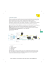
FIELD GUIDE
DeviceNet™
Troubleshooting
G1001
Publised 11/11/2013
SCOPE
T
he purpose of this troubleshooting guide is to direct qualified service personnel to the causes of network problems
and provide remedies. The primary goal of troubleshooting is to minimize network downtime. Test procedures
described in this Troubleshooting Guide require the use of test equipment to measure voltage, current, and
resistance of the physical media layer. It is usually sufficient to have a true RSM multimeter, such as Fluke ® 87-3 Digital
Multimeter or similar to run tests and obtain reliable measurements. For information on designing DeviceNet™ systems,
refer to ODVA publication 27: “DeviceNet Planning and Installation Manual”.
1.1 Network Components
DeviceNet uses a trunk line and drop line topology to connect nodes for communication. Here is an example:.
TR
Trunk Line NODE
NODE
TapT
Trunk Line
ap
POWER
SUPPLY
Drop Line
NODE
NODE
TR
Drop Line
NODE
TR = Terminating Resistor
Component
Trunk Line
Drop Line
Tap
Terminating Resistor
Node
Power Supply
2
Description
The network cable between terminators. It is usually a
“thick” cable.
The network cable between the trunk and nodes. Each
drop line may be no longer than 6 meters (20 feet)
A branching point from the trunk line. There may be one
node on a drop line, as with a tee tap, or multiple drop
lines, as with a multiport junction box.
The 121 Ohm resistor that is connected to the end of the
Trunk Line. There are two terminators per network.
An addressable device that communicates on the
network. There may be as many as 64 nodes per network.
The 24-volt DC source that powers network
communication. There may be multiple power supplies
on a network, located anywhere on the network.
www.turck.com • 1-800-544-7769 • Fax: (763) 553-0708 • TURCK • Minneapolis, MN 55441
Wiring and Connector Pin Definitions
There are five conductors in DeviceNet™ cables. There are three connector types commonly used on DeviceNet systems:
7/8 16 minifast ® (mini), M12 eurofast ® (micro), and screw terminal (open). Table I shows the connector pin definitions
and Table II shows the connector styles.
Name
Shield Drain
V+
VCANH
CANL
Wire Color
Bare
Red
Black
Blue
White
Description
Connection to the shields in the cable
Connection to the bus 24 VDC supply
Connection to the bus supply common (0 VDC)
Data connection (high differential)
Data connection (low differential)
DeviceNet™ Cable Classification
Table I: Pin Definitions
Male mini
Connector
Female mini
Connector
1 = Bare (Drain)
2 = Red (V+)
3 = Black (V-)
4 = White (CANH)
5 = Blue (CANL)
Male micro
Connector
Female micro
Connector
1 = Bare (Drain)
2 = Red (V+)
3 = Black (V-)
4 = White (CANH)
5 = Blue (CANL)
Open Female Connector
Rear View
5 = Red (V+)
4 = White (CANH)
3 = Bare (Drain)
2 = Blue (CANL)
1 = Black (V-)
Table II: Connector Styles
minifast (mini)
eurofast (micro)
Open Style Front View
Male Connectors
Female Connectors
www.turck.com • 1-800-544-7769 • Fax: (763) 553-0708 • TURCK • Minneapolis, MN 55441
3
DeviceNet™ cables are classified according to DeviceNet Specification1 as:
Round Cables
•
Thick Cable or Cable II
•
Thin Cable or Cable I
Flat Cables
Table III: Cable Specifications (provides data for each cable type listed in the DeviceNet Specification)
Data Pair
Min. Conductor Size:
19 strands min.
Insulation Diameternominal
Color
Impedance
Max. Propagation Delay
DCR - at 20 degrees C (max)
Tape Shield
Power Pair
Min. Conductor Size
Insulation Diameternominal
Color
DCR - at 20 degrees C
Tape Shield
General Specifications
Outside Diameter
Bent Radius (d = diameter)
Drain Wire
Agency Certification
Overall Shield
4
Thick Cable
#18
Cable II
#18
0.150 in
0.150 in
1.36 nSec/ft
6.9 Ohms
/1000 ft
2 mil/1 mil,
Al/Mylar
0.077 in
CAN_H White
CAN_L Light Blue
120 Ohm +/10% @ MHz
1.36 nSec/ft
1.36 nSec/ft
6.9 Ohms
6.9 Ohms
/1000 ft
/1000 ft
1 mil/1 mil,
2 mil/1 mil,
Al/Mylar
Al/Mylar
#15
0.098 in
#15
0.098 in
3.6 Ohms
/1000 ft
1 mil/1 mil,
Al/Mylar
3.6 Ohms
/1000 ft
1 mil/1 mil,
Al/Mylar
0.410 - 0.490”
Specified by
Vendor
Suitable for
Application
#18
Compliant
w/ local gov’t
regulations
Braid
36 AWG or
0.12 mm Cu
7 x d, fixed
20 x d, flex
#18
NEC (UL)
CL2/CL3 min.
Braid
36 AWG or
0.12 mm Cu
Thin Cable
#24
#22
0.055 in
V+ Red
V- Black
17.5 Ohms
/1000 ft
1 mil/1 mil,
Al/Mylar
0.240 - 0.280”
7 x d, fixed
20 x d, flex
#22
NEC (UL)
CL2/CL3 min.
Tape
1 mil/1 mil,
Al/Mylar
Cable I
#24
Flat Cable
#16
0.077 in
0.110 in
1.36 nSec/ft
28 Ohms
/1000 ft
1 mil/1 mil,
Al/Mylar
1.60 nSec/ft
4.9 Ohms
/1000 ft
N/A
#22
0.055 in
#160
0.110 in
17.5 Ohms
/1000 ft
1 mil/1 mil,
Al/Mylar
4.9 Ohms
/1000 ft
N/A
Specified by
Vendor
Suitable for
Application
#22
Compliant
w/ local gov’t
regulations
Tape
1 mil/1 mil,
Al/Mylar
N/A
10 x
diameter
N/A
NEC (UL)
CL2 min.
N/A
www.turck.com • 1-800-544-7769 • Fax: (763) 553-0708 • TURCK • Minneapolis, MN 55441
Thick Cable and Cable II
The maximum cable length used in trunk-drop topology depends on the data rate:
Table IV: Thick Cable and Cable II Topology
Communication Rate
125 kb
250 kb
500 kb
Network Length
500 m (1640ft)
250 m (820 ft)
100 m (328 ft)
Trunk Length
500 m (1640 ft)
250 m (820 ft)
100 m (328 ft)
Maximum Drop
6 m (20ft)
6 m (20 ft)
6 m (20 ft)
Cumulative Drop
156 m (512 ft)
78 m (256 ft)
39 m (128 ft)
The length of the network is the sum of the trunk length and cumulative drop length.
Thick Cable Capacity
The power distribution chart, Figure 1, shows the maximum allowed current through the power conductors of the thick
cable. Distance is measured from a single 24 VDC power source. If the maximum current exceeds the specified value
at any given point on the network, the power supply systems should be re-designed. Figure 1 provides thick cable
current ratings.
Maximum Current Capability (amps)
Figure 1: Current available through power conductors of thick cable
8.00
8
7
6
5.42
5
4
2.93
3
2.01
2
1.53
1
0
0
50
(164)
100
(328)
150
(492)
200
(656)
1.23
250
(820)
1.03
300
(1984)
0.89
350
(1148)
0.78
400
(1312)
0.69
450
(1476)
500
(1640)
Length of Network in meters (feet)
Thin Cable and Cable I
The maximum cable length used in trunk-drop topology, based on the data rate is:
Table V: Thin Cable and Cable I Topology
Communication Rate
125 kb
250 kb
500 kb
Trunk Length
100 m (328 ft)
100 m (328 ft)
100 m (328 ft)
Maximum Drop
6 m (20 ft)
6 m (20 ft)
6 m (20 ft)
www.turck.com • 1-800-544-7769 • Fax: (763) 553-0708 • TURCK • Minneapolis, MN 55441
Cumulative Drop
100 m (328 ft)
78 m (256 ft)
39 m (128 ft)
5
Thin Cable Capacity
Figure 1: Current available through power conductors of thick cable
Maximum Current Capability (amps)
Power distribution chart: Figure 2,
shows the maximum allowed current
through the power conductors of the
thin cable. The distance is measured
from a single 24 VDC power source.
If the maximum current exceeds the
specified value at any given point
of the network, the power supply
system should be re-designed. Figure
2 provides thin cable current ratings.
3.00
3
2.06
2
1.57
1.26
1
1.06
0.91
0.80
0.71
0.64
0
01
02
(33)
03
(66)
04
(98)
06
(131)
50
07
(164) (197)
09
(230)
80
0
100
(262) (295) (328)
Length of Network in meters (feet)
Flat Cable
The maximum flat cable length used in trunk topology, based on the data rate is:
Table VI: Flat Cable Topology
Communication Rate
125 kb
250 kb
500 kb
Trunk Length
420 m (1378 ft)
200 m (656 ft)
100 m (328 ft)
Maximum Drop
6 m (20 ft)
6 m (20 ft)
6 m (20 ft)
Cumulative Drop
156 m (512 ft)
78 m (256 ft)
39 m (128 ft)
Flat Cable Capacity
Figure 3: Current available through power conductors of flat cable
Maximum Current Capability (amps)
9
8.00
8
7
6
5.65
5
4
3
2.86
2
1.91
1.44
1
0
1.15
0.96
0.82
0
12.52
(41)
55
(82)
0
(164)
100
(328)
150
(492)
200
(656)
250
(820)
300
(984)
350
(1148)
0.72
0.69
420
400
(1312) (1378)
Length of Network in meters (feet)
6
www.turck.com • 1-800-544-7769 • Fax: (763) 553-0708 • TURCK • Minneapolis, MN 55441
QUICK START
Know the Network Layout
An essential part of the troubleshooting process is knowing the layout of the network. Survey the network to determine
the location (or existence) of these components.
Network Topology
•
The trunk cable connects nodes and taps. Look for a terminating resistor at each end.
•
The drop lines are the non-terminated cables that connect nodes to the trunk.
Location of Nodes
•
Count the nodes and note their location on the network.
Location of Power Supplies
•
There may be more than one power supply on a network, located at the end, middle, or anywhere along the cable. Only one of
the power supplies must be the grounding point for network power.
When Things Go Wrong
The first question is always “What has changed?” If you have added or replaced nodes, changed wiring, or configured
a scanner, start to look for a problem where you were working. If you cannot find a problem there, you will need
to determine if the problem is caused by the physical media, a node communication fault, or the network power
distribution. It is sometimes difficult to determine the root problem, because there can be more than one network
problem. In general, check for physical media and node configuration problems before network power distribution or
isolating node communication faults.
Symptoms of Physical Media Problems
For This Symptom
All nodes on a trunk segment or
on a drop stop communicating
then may recover or go bus-off.
Nodes sporadically stop
communicating, and then recover.
The network communicates
only when the number of nodes
or trunk length is reduced.
Take This Action
Check all wiring and connectors on
the segment between the power
supply and the terminating power.
Check for loose wiring or a loose
connector leading to the node.
Check the resistance between
conductors on the bus cable,
CAN DC resistance, and
terminating resistor values.
www.turck.com • 1-800-544-7769 • Fax: (763) 553-0708 • TURCK • Minneapolis, MN 55441
See Procedure
3.1
3.1, 3.2, 3.3
3.3
7
Symptoms of Node Problems
For This Symptom
Slave node is on-line, but the
scanner says it does not exist.
Slave node will not go on-line.
The network communicates only
when the node is removed.
The node is in the I/O timeout state.
Take This Action
Change the slave node address to
match scanner’s scan list.
Check CANH/CANL wiring.
See Procedure
3.6
Change the slave node data rate to
match the scanner’s data rate.
Check the node’s CAN transceiver.
4
Reset the scanner and network power.
3.4
3.4
3.4, 3.5
Symptoms of Network Power Distribution Problems
Network power distribution problems often produce sporadic or intermittent network failures.
For This Symptom
Nodes near the end of the
trunk stop communicating
after operating normally.
The scanner or multiple nodes
go to the bus-off state after
operating normally.
The scanner does not detect
properly configured slave nodes.
The network communicates only
when the number of nodes or
the trunk length is reduced.
Take This Action
Check the bus voltage at the node and the
common mode voltage at the ends of the bus.
See Procedure
3.3 - 3.4
Check common mode voltage and
power supply/shield grounding.
3.2 - 3.3
Check power supply/shield grounding
and common mode voltage.
Check the bus voltage at the node and . the
common mode voltage at the ends of the bus.
3.2 - 3.3
3.2
Network Failure
Network cannot go on-line, Bus-off condition (error 91).
For This Symptom
The network communicates only
when the number of nodes or
the trunk length is reduced.
8
Take This Action
Check bus voltage at node and common
mode voltage at ends of bus.
Check each node for Data Rate setting.
Check each node for CAN transceiver failure.
Check open style and field wireable
connectors for proper wiring.
See Procedure
3.3 - 3.4
3.2 - 3.3
3.2 - 3.3
3.2
www.turck.com • 1-800-544-7769 • Fax: (763) 553-0708 • TURCK • Minneapolis, MN 55441
NETWORK TESTS
Termination Test
Description
Procedure
If Measured
Values are:
Termination is used to match the impedance of a node to the impedance of the
transmission line being used. When impedances are mismatched, the transmitted
signal is not completely absorbed by the load and a portion is reflected back
into the transmission line. If the source, transmission line and load impedance
are equal, these reflections are eliminated. This test measures series resistance
of DeviceNet™ data pair conductors and attached terminating resistors.
1. Turn all network power supplies off..
2. Measure and record DC resistance between CANH and
CANL at the middle and end of the network.
<50 Ohms
Check for more than two terminating resistors.
Check for short-circuit between CANH and CANL wiring.
Check nodes for faulty transceivers (refer to CAN Transceiver Resistance Test).
60 Ohms
Normal - do nothing.
71-121 Ohms Check for open circuits in CANH or CANL wiring..
Problem Resolution •
Check for one missing terminating resistor.
Split the network down the middle into two segments.
•
Check resistance of each segment - should be 121 Ohm since only a single.
•
terminating resistor is present on each segment.
•
Mark a break point and leave it disconnected.
•
At least one segment will show resistance = to 121 Ohm.
•
Split a bad segment into two sections and add, temporarily, a terminating resistor.
•
to the non-terminated section. Mark the location of the break point and temporary.
•
terminating resistor.
•
Check the resistance of each section - should be 121 Ohm.
•
Continue splitting the network until the problem is located and repaired.
•
Remove all temporary resistors and bring network back to original state.
•
Verify once again that the assembled network has 60 Ohm resistance.
The same procedure is used to locate connector shorts or faulty transceivers.
www.turck.com • 1-800-544-7769 • Fax: (763) 553-0708 • TURCK • Minneapolis, MN 55441
9
Power Supply Ground Test
Description
Procedure
The shield and V- of the DeviceNet™ cable system must be grounded at a single
location as shown in Figure 4, preferably near the physical center of the network. If
multiple power supplies are present, ground only at the power supply closest to the
middle of the network. This test will indicate if multiple grounds are connected.
1. Turn off all network power supplies..
2. Disconnect V- and Shield wires are from earth ground and from each other.
3. Measure and record the DC resistance between Shield and
earth ground at the far most ends of the network..
If Measured
Values are:
Note:
4. Connect the V- and Shield wires to earth ground.
<1 M Ohm
Check for additional grounded V- or Shield wires
>1 M Ohm
Normal Range
Grounding wire could be up to 10-ft long. Grounding is done with:
•
1” copper braid, or
•
#8 AWG copper wire up to 10-ft long
Figure 4: Network Grounding
Power Tap
CAN_H
CAN_L
SHIELD/DRAIN
VV+
FUSE
FUSE
SCHOTTKY
DIODE
Power Supply
Cable
#15AWG
GND
V- V+
Network PS
10
www.turck.com • 1-800-544-7769 • Fax: (763) 553-0708 • TURCK • Minneapolis, MN 55441
Power Common Mode Voltage Test
Description
Procedure
When the current is drawn through the power pair on the DeviceNet™ trunk line, the
resistance of the power pair conductors produces the common mode voltage drop.
The effect of the common mode voltage is that the V+ line decreases from the 24 VDC
at the power supply as you move farther from the power supply. More significantly,
the V- line increases from the 0 VDC value at the power supply along the length of the
trunk line. This test assumes that V+ decreases and V- increases are equal. Since CANH
and CANL both are referenced to the V- wire, if the voltage on the V- line varies more
than 4.65 VDC at any two points the CAN transceivers will fail to operate properly.
1. Turn all network power supplies on.
2. Configure all nodes for their maximum current draw from network
power. Turn on outputs that use network power.
3. Measure and record DC voltage between V+ and V- where
each power supply connects to the trunk.
If the difference
between any
two measured
values is:
4. Measure and record DC voltage between V+ and V- at the ends of the network.
<9.3 Volts
Normal Range
>9.3 Volts
Network will not operate properly. Possible solutions:
•
Shorten overall length of the network cable
•
Move power supply in direction of overloaded section
•
Move nodes from overloaded section to less loaded section
•
Move high current loads close to the power supply
•
Add a second power supply
•
Break the network into two separate networks
www.turck.com • 1-800-544-7769 • Fax: (763) 553-0708 • TURCK • Minneapolis, MN 55441
11
CANH/CANL Voltage Test
Description
Procedure
Each node contains a CAN transceiver that generates differential signals onto the data
conductors. When the network communication is idle, the CANH and CANL voltages
are approximately 2.5 volts. Faulty transceivers can cause the idle voltages to vary and
disrupt network communication. Although this test indicates that faulty transceivers
may exist on a network, it will not indicate which node has the faulty transceiver. If a
node with a faulty transceiver is found, perform the CAN Transceiver Resistance Test.
1. Turn all network power supplies on.
2. Configure all nodes for their maximum current draw from network
power. Turn on outputs that use network power.
3. Measure and record DC voltage between V+ and V- where
each power supply connects to the trunk.
If CANH and/or
CANL are:
4. Measure and record DC voltage between V+ and V- at the ends of the network.
<2/0 Volts
• CANH/CANL conductor has
intermittent short to shield or V-.
•
Check all open style and field wireable connectors.
•
Check CANH and CANL conductors for continuity.
•
2.0 - 3.0 Volts
>3.0 Volts
Possible faulty transceiver on one or mode
nodes (refer to CAN Transceiver).
Normal Range.
• CANH/CANL conductor has intermittent short
to V+. Network in bus-off state (error 91). Check
all open style and field wireable connectors.
•
CAN Levels
Recessive
Dominant
12
Parameter
CANH
CANL
CANH - CANL
CANH
CANL
CANH - CANL
Check for excessive common mode voltage
(refer to Power Common Mode Voltage Test).
Range
2.0 - 3.6
2.0 - 3.6
0.45 maximum
2.75 - 5.1
0.5 - 2.86
0.95 minimum
www.turck.com • 1-800-544-7769 • Fax: (763) 553-0708 • TURCK • Minneapolis, MN 55441
CAN Transceiver Resistance Test
Description
Procedure 1
The CAN transceivers used in DeviceNet™ nodes have one circuit that controls CANH and another
circuit that controls CANL. Experience shows that electrical damage to one or both circuits
may increase the leakage current in these circuits. This test uses an ohm/meter to measure the
current leakage through the CAN circuits. Note: The reference values listed below are derived
from tests with Philips Model PCA82C251 CAN transceivers and Fluke® multimeter Models
77 and 87. Other combinations of transceivers and multimeters may yield different results.
1. Disconnect the node from the network. Leave the node unpowered.
2. Measure and record the DC resistance between CANH and V-.
3. Measure and record the DC resistance between CANH and V+.
4. Measure and record the DC resistance between CANL and V-.
If Measured
Values are:
Procedure 2
If Measured
Values are:
5. Measure and record the DC resistance between CANL and V+.
<1 M Ohms
Faulty CAN transceiver
4 M - 6 M Ohms
Normal Range
>6 M Ohms
Faulty CAN transceiver
Measure resistance between CANH (signal probe) and CANL (common probe)
<36 Kohms
Faulty or deteriorated CAN transceiver
36> Kohms <39
Normal Range
ESD Discharge Test
Description
Procedure 1
The following test shows if power and communication lines are affected by an electrostatic
discharge. ESD may cause damage to the nodes and disrupt network communication. Every
node is affected by discharge and in the long run most components will deteriorate, thus
reducing network performance and reliability. A repeated node failure in the same production
area indicates that an ESD discharge is above the components ratings. Transceiver PCA82C251
is rated for +/- 250 VDC ESD discharge, classification B, machine model: C=100 pF, R=0 Ohm.
Tektronix ® scope model THS730A, 200 Mhz, 1 GSs, or similar may be used for ESD test.
1. Connect Channel 1 to CANH and set voltage reference to 500 V.
2. Connect Channel 2 to CANL and set voltage reference to 500 V.
3. Set differential signal CANH - CANL.
4. Set time reference to 200 nsec.
5. Set trigger point at CH 1, at 250 V.
If CANH
Measured
Values are:
6. Measure voltage and adjust reference levels as required.
<200 VDC
Acceptable ESD discharge
>200 VDC
Control systems must be grounded
www.turck.com • 1-800-544-7769 • Fax: (763) 553-0708 • TURCK • Minneapolis, MN 55441
13
SETTING NODE ADDRESS AND COMMUNICATION RATE
The methods described below are used on TURCK and DeviceNet™ products and may be different than other vendors’
implementations. The default node address is 63 and the communication rate is set at 125 kbps (kilobits per second). The
node address and communication rate parameters can be set in hardware or software. The factory default is Software
Configuration. Changes to DIP switch settings take effect the next time the device is powered up or when the device
receives a software reset.
3
FF
4
5
6
7
8
S1 - S6 Set
Node Address
S7 - S8 Set
Comm Rate
7
7
125 kbps
250 kbps
2
3
FF
500 kbps
S7 - S8 are
switched ON
1
O
8
8
8
Software configuration of node addresses and communication rates is active
when DIP switches S7 and S8 are ON. The node address and communication
rates are stored in nonvolatile memory. Changes to the node address and
communication rate require the use of a DeviceNet configuration tool.
Switches S1-S6 are ignored when in software configuration mode.
O
7
Software Address/Comm Rate Configuration
2
Hardware configuration of node addresses and communication rates is
accomplished using DIP switches located under the device cover. Switches
S7 and S8 adjust the communication rate and switches S1-S6 set the node
address using binary code. Switch S1 is the least significant bit and switch
S6 is the most significant bit.
1
Hardware Address/Comm Rate Configuration
4
5
6
Rotary Switches
7
14
8
Rotary switches provide a more convenient and reliable way of setting the
node address or data rate.
www.turck.com • 1-800-544-7769 • Fax: (763) 553-0708 • TURCK • Minneapolis, MN 55441
The MSD (the Most Significant Digit) switch sets a tenth
digit and the LSD (the Least Significant Digit) sets a single
digit. The valid address range is 0-63.
The MSD switch set to the PGM (programmable) position
allows use of node commissioning or software setup of
the node address.
Node Address (00-63)
1
23
1
4
5
0
6
PGM
MSD
23
4
9
250
5
0
7
8
LSD
6
Data Rate
500 Auto
125
PGM
The Data Rate switch, when available, is used for the
selection of a pre-defined communication speed. In
“Auto” position, the node detects the Data Rate through
“Autobaud”. It usually takes several poll messages to be transmitted for the node to “lock” in the appropriate Data Rate.
In addition to these four predefined positions, the Data Rate switch can be set to “PGM” (programmable mode). The PGM
position is any nonpredefined position.
Changes to the rotary switch settings take effect the next time the device is powered up or when the device receives a
software reset.
www.turck.com • 1-800-544-7769 • Fax: (763) 553-0708 • TURCK • Minneapolis, MN 55441
15