1
MVCS User Manual
________________________________________________________________________________________________________________
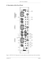
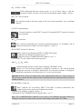
(12) SET / OPERATE switch
Two position switch to set the mode of operation. In SET position the electrode outputs
are connected to an internally grounded load and no COMPENSATION signal is
generated. Thus, the SET position is used to preset the desired values at the EJECT /
RETAIN controls on a well defined basis. In the OPERATE position, the current preset at the
EJECT / RETAIN controls will flow through the electrode.
(13) HEADSTAGE connector
8 pole connector for the HEADSTAGE (MVCS-C systems) or for the cable directly
connected to the injecting electrode (MVCS systems).
Important: Always turn power off when connecting or disconnecting headstages from the 19"
cabinet (see also chapter 1).
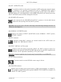
(14) NORMAL / INVERTED switch
Switch to set polarity of EJECT and RETAIN current: NORMAL = EJECT positive,
RETAIN = negative.
(15) TTL connector
Optically isolated BNC connector for external control in the AUTO mode (see
also 16). LO = RETAIN, HI = EJECT.
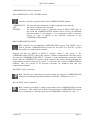
(16) EJECT / RETAIN / AUTO switch
Switch to select the mode of operation. EJECT: the EJECT current set with (7) is
applied to the electrode. RETAIN: the RETAIN current set with (17) is applied to the
electrode. AUTO: Operation controlled by a TTL pulse at (15).
Remember: Current is applied to the electrode only if switch (12) is set to OPERATE.
(17) RETAIN potentiometer
Ten-turn control to set the RETAIN current, range 0-100 nA.
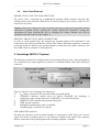
(18) GROUND connector
Banana jack providing system ground (same as GND at the headstage, see chapter 5).
This ground is isolated from power ground (PROTECTIVE EARTH, see chapter 4.2)
and the TTL INPUT ground.
___________________________________________________________________________
version 4.9
page 11