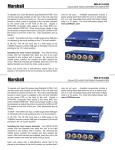
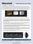
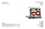
1
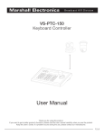
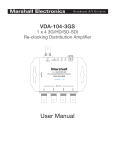
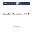
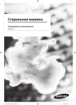
Marshall Electronics
Broadcast A/V Division
Model No. V-SG4K-HDI
4K HDMI portable signal generator
HDMI 2.0 with 4K x 2K 60Hz 4:2:0
Operating Instructions
V.1.0
V-SG4K-HDI / Introduction
Marshall Electronics
Table of Contents
1. Introduction...................................................................... 3
2. Product overview.............................................................. 3
3. Features............................................................................ 4
4. Specifications................................................................... 5
5. Package Contents............................................................ 5
6. Quick Access Keys........................................................... 6
7. Computer Control............................................................. 7
8. Installing the Control Application Software...................... 15
9. Warranty........................................................................... 17
10. Contact Information....................................................... 18
1. Introduction
V-SG4K-HDI is a programmable UHD (Ultra High Definition) capable Test Pattern Generator,
packed with features for video and audio testing of HDMI® sources, sinks and extenders.
V-SG4K-HDI Generates standard format signals up to 4K x 2K 60Hz 4:2:0 which is recently defined
as part of the HDMI® 2.0 specification (UHD).
Thanks to its small size and low power consumption (only 0.4A) the VSG4K-HDI can be powered
from practically any USB power source. It is highly portable and can easily fit into a toolbox or be
used in an array of daisy chained devices for product development/testing. Several can fit on a 19”
Rack shelf.
The V-SG4K-HDI has a built in 0.95-inch AMOLED display, which shows the generated pattern and
format setting parameters.
A professional programmable sine wave generator is integrated for performing audio tests and
when needed, an external analog audio source can be used via a 3.5 mm stereo socket on the rear
panel. This input accepts an unbalanced 1V/pp stereo analog audio source.
V-SG4K-HDI is programmable via the USB connector or via the RS-232 3-pin Phoenix connector.
Advanced control is available through the included Windows® compatible software application.
For purposes of creating large test systems or multi-device measurement protocol functionality,
customers can use the serial Loop-Out port via second Phoenix 3 pin terminal.
Through this functionality, users can set up a large test system by “daisy chaining” multiple
V-SG4K-HDI generators. This can be useful to test UHD distribution devices or complex UHD
networks for example.
2. Product Overview
1
3
2
IMPORTANT SAFETY INSTRUCTIONS:
• Please read User Guide before using this product.
• Please keep User Guide for future reference.
• Please read the cautions to prevent possible danger and loss of property.
2
1. A 0.95-inch AMOLED displays the generated signal and menu settings.
2. Status LED. Shows HDMI link status. When the link is lost or HPD (Hot Plug Detect) is not present from the device being tested, the LED will be off.
When there is an EDID error, the LED will blink.
3. Quick Access Push Buttons.
www.LCDracks.com
3
Marshall Electronics
V-SG4K-HDI / features
Made in China
•
•
•
•
REAR PANEL
Audio In
Rx Tx
HDMIOut
Out
HDMI
1
Rx Tx
RS232 (PC) Loop Out
2
3
4
USB
5
DC5V
6
7
1. HDMI test signal output port.
2. HDMI retention screw / grounding screw
3. RS-232 control port Phoenix connector (serial control in)
4. RS-232 loop-out port Phoenix connector (serial control to next Generator)
5. USB control port. Used to operate a single unit from a computer. Can also be used to supply power to the V-SG4K-HDI.
6. 5-Volt DC socket for use with the included power supply
7. 3.5 mm stereo jack for connecting audio from external unbalanced audio sources. This analog audio is embedded into HDMI digital test signal. (This function is selectred via the Control Application Software.)
3. Features
•
•
•
•
•
•
•
•
•
•
•
4
Designed for R&D engineers, video engineers and AV integrator / installers.
Supports latest 4K x 2K, HD, SD and 3D at multiple frame rates
Supports multiple sample structures including: RGB4:4:4, YUV4:4:4, YUV4:2:2,YUV4:2:0 (HDMI 2.0)
Small size 3.25” x 3.8” (83mm x 97mm) and lightweight.
Very low power consumption (less than 0.4A at 5V)
34 preset video test patterns.
32 preset resolutions, 10 user-defined resolutions plus auto resolution mode based on the EDID from the connected device.
OLED display for Output Pattern preview and Menu settings display.
Supports 7 audio sample rates plus auto mode based on the EDID data of the connected device.
Supports standard functionality such as HDMI/DVI, Deep color, HDCP (on/off), selectable color sampling, etc.
Supports EDID read functionality (stores10 EDID sets of different device parameters).
Stored EDID data can be written to external devices via the USB port.
Control Software SGCS-ver.01.8 supplied with V-SG4K-HDI adds easy operation and extended generator functionality.
Test many types of HDMI devices including matrix routers, switchers, splitters, TV sets, monitors, extenders, etc.
Link multiple units together to create complex test systems for manufacturing, QC and QA applications.
The Pattern Generator’s sophisticated functionality and small size make it virtually irreplaceable for AV professionals.
4. Specifications
Product
HDMI 2.0 compatible signal generator
HDMI Version
HDMI2.0 / DVI
HDCP on/off
Yes
Video Bandwidth
Up to 9.0GHz (3.0GHz per channel)
Color Depth
24bits, 30bits, 36 bits, 48bits
Preset Video Formats
32 presets including:
4K(30/29), 4K(25), 4K(24), 4K(50), 4K(60/59), 720P-3D,1080P-3D
plus fixed timing and AUTO detect mode
User Defined Timing
Up to 10 User presets
Test Patterns
34 (33 2D and one 3D pattern)
Color Sampling
RGB444, YUV444, YUV422, YUV420 (HDMI2.0 only)
Audio Bit Depths
26, 24, 20-bits
Audio Sample Rates
32, 44.1, 48, 88.2, 96, 176 ,192KHz
Vertical Frequency Range
Supports frame rates up to 120 Hz
Power Consumption
2 Watts (max)
Housing
Metal
Dimension W/H/D
3.25” x 1.25” x 3.8” (83mm x 32mm x 97mm)
Weight
0.6lbs (280 gm)
5. Package Contents
1. Main unit: V-SG4K-HDI
2. 5VDC 1A Power Supply
3. Mounting ears (x2)
4. 1.2m USB A-to-A cable (x1).
5. Phoenix plug (x2)
6. Disk with Control Application
www.LCDracks.com
5
V-SG4K-HDI / Computer Control
Marshall Electronics
6. Quick Access Keys
The front panel Up/Down, Left/Right, Enter and Cancel keys provide quick access to the most
common functions in the V-SG4K-HDI signal generator. (Detailed computer control is available
through the USB or RS-232 ports.)
Up / Down:
Use the Up/Down keys to quickly cycle through the 33 preset standard test patterns plus one
additional 3D pattern.
Left / Right:
Use the Left/Right keys to quickly cycle through 32 preset video formats.
(Additional formats are available through the PC application).
Enter / Cancel:
Pressing the Enter key opens the system menu. Use the Left/Right keys to select different menu
categories. Use the Up/Down keys to modify items in the selected category.
Press Enter a second time to accept a selection.
Press Cancel to exit out of the category or menu.
Menu categories:
• Timing (Format)
• Color Space (Sampling)
• Color Depth (Bits per Color)
• HDCP (On/Off)
• HDMI/DVI (Feature Set)
• Audio Sample Rate (KHz)
• Audio resolution (Bit per Sample)
• External audio (On/Off)
• Audio channel (Number of Channels generated up to 8)
• Output standby (Output On/Off) – (Standby ON turns output OFF)
• Save EDID (Save EDID information from connected Device)
• EDID Info (Display EDID data from connected Device)
• Address Info (Display RS-232 Group and Device Address) changed via PC application
6
7. Computer Control
Provided with the V-SG4K-HDI is a Windows application which allows very detailed operation
from a computer. Perhaps the easiest connection method is via a standard USB cable. Once the
application is installed on a PC, simply connect a USB (A-to-A) cable between the computer and
the signal generator and open the application. The V-SG4K-HDI can receive power over this same
cable so an external power supply will likely not be necessary. See section 8 “Installing the Control
Application Software”.
The same application may be used to control the test generator via an RS-232 “serial” connection.
Select the active serial “Com” port the computer is using in the application to complete the
connection. The RS-232 serial connection does not supply power. The unit will need to be either
connected to a USB source or powered by the included 5-volt power supply.
All functions can be controlled either via the USB or RS-232 interface. The primary difference is that
RS-232 can be used to control several devices in a chain while USB controls just a single device.
Basic Operations
- Connect the PC to the Signal Generator using USB or RS-232. Click the “Search Device” button in the Main Menu. Within a few seconds, the Comm Port Activity light will turn red indicating that the PC has control of the Signal Generator.
- Connect an HDMI cable from the Generator to the device (monitor, recorder, etc.) that you want to test.
- Select the Timing tab to set the Generator to the appropriate video format for the device you will be testing.
- Select the Pattern tab to choose an appropriate test pattern
Main menu:
The Main menu runs down the left side of
the screen.
Sub-menus are accessed through Tabs
along the top of the screen.
Main Menu Functions:
- Output On/Off
- Serial “Comm” port selection (a USB connection will also have a port number)
- Search for attached device (starts control whether connected via USB or RS-232)
- Device address management
- HDP (Hot Plug Detect) Indicator
- Video Output Status Display
- Audio Output Status Display
www.LCDracks.com
7
V-SG4K-HDI / Computer Control
Marshall Electronics
Sub-Menu Tabs:
Timing Details Menu page
Timing Menu (video format) page:
Timing Menu - Applications
- The timing page allows selection of a very wide range of video and computer display formats.
- Select the appropriate format for the device under test.
- Check and confirm the range of different formats a device will accept
- Force error conditions in a device to confirm how it displays error messages
- Use the generator as a substitute for another source that is suspected of malfunctioning
- Check HDMI cables and connections
8
Timing Details Menu - Applications
The Timing Details page is useful for testing the limits of a particular device. This can be particularly
useful for product development
- Adjust H & V timings and frequencies to determine the acceptance range of the device
- Create special timing parameters for new devices and formats not already included in the Signal Generator.
- Force error conditions in a device to understand how it will react to non-standard inputs
www.LCDracks.com
9
V-SG4K-HDI / Computer Control
Marshall Electronics
Pattern Menu page
Pattern Menu - Applications
The Pattern page is probably the most frequently used section of the Signal Generator.
A wide variety of standard and unique patterns are available. Each of these patterns can be output at
any of the selected timings/formats including UHD/4K (3840 x 2160).
- Color bars are useful for checking monitors, wavform monitors and vectorscopes as well as checking luma and chroma levels through switchers, scalers and other system components.
- Solid color screens can be used to check purity in displays and projectors.
- Ramp patterns are good for checking bit depth by observing the degree of “stepping” in the image.
- Multiburst is useful for checking the bandwidth of a device as well as its tendency to create alias patterns.
- Lines and checkerboards are particularly useful when setting up projection systems and video walls.
10
Setting Menu page
Setting Menu - Applications
The Setting page is a collection of the basic signal parameters, both video and audio, that the Signal
Generator can output.
- Most of the settings are used for checking that a device conforms to the stated specifications. This includes color space, color depth, audio sample rate, bit depth and number of channels.
- External audio (stereo) can be selected also so that specialized audio signals may be embedded into the HDMI output from other sources.
- HDCP On/Off provides a quick check for HDCP (copy protection) compliance of a device. Turning the HDCP test ON will cause the picture to disappear on recorders, switchers and any other non-
display device. Compliant display devices (monitors, TV’s, projectors) should display a picture with HDCP turned ON.
www.LCDracks.com
11
V-SG4K-HDI / Computer Control
Marshall Electronics
EDID Menu page
Address Setting Button (in Main Menu)
Address Setting Menu - Applications
The Address Setting button in the Main Menu area (left side of screen) opens the Address Setting
menu. This section is used when it is desired to link together several Signal Generators to perform
multiple tests at the same time. This is a particularly useful feature for manufacturing, QC and QA
applications. As shown below, Signal Generators may be connected to each other in a “cascade” or
“daisy chain” fashion linking the RS-232 output from one unit to the RS-232 input of another. For this
method to operate correctly, each Generator needs to be given an Address number (and optionally, a
Group number). Also, a Generator can be given a text name.
EDID Menu - Applications
The EDID page has a variety of uses and is useful for checking the capabilities of a given device.
- Simply click the EDID Read button and the EDID data will appear on screen. (If that does not occur, please check that the HDMI cable is firmly connected on both ends).
- The EDID page displays information about the manufacturer and basic characteristics in the General Information window.
- Details about Video and Audio formats supported by the device are displayed in the Video Information and Audio Information windows.
- The raw EDID data is also presented in hexadecimal format for detailed analysis. This data is primarily useful for device manufacturers.
- The V-SG4K-HDI Signal Generator can save up to 10 sets of EDID data to a PC for analysis and comparison.
12
- To create an Address, each Generator should be connected, one-at-a-time to a PC running the Control Application.
- Click on the Address Setting button.
- In the Address Setting menu, in the New Address area, type in a two-digit Address and Group number (a common Group number like 01 will be fine for most applications).
- Click on the Write Address to Device button to set this Address.
- Click on the Save button before exiting the Address Setting page.
Once each Generator has been assigned a unique Address and all the Generators are connected
together, it is simple to select each generator from the Main Menu.
- First, click the Search Device button. Within a few seconds all of the Generators will be detected.
- Next, click on the pulldown window located just below the words “Address Management” in the Main Menu area. A list of all connected devices will appear.
- Simply click on the Address of the Generator you wish to control and make the desired settings through the various menu tabs.
www.LCDracks.com
13
Marshall Electronics
V-SG4K-HDI / Installing the Control Application Software
HDMI Matrix, Switcher or Splitter
USB cable
(Or use RS232 cable
which is terminated
with Phoenix
connector
HDMI cable
V-SG4K-HDI
Up
Left
Enter
V-SG4K-HDI
Right
Status Down
hdmI signal generato r
Up
Left
Enter
Status Down
Cancel
hdmI signal generato r
V-SG4K-HDI
Right
Up
Left
Enter
Right
Status Down
Cancel
hdmI signal generato r
RS-232 Connection Method:
DB-9 Serial Connector (PC)
Phoenix 3-pin Connector
Pin 2 (TX)............................................................... Pin 1 (RX)
Pin 3 (RX).............................................................. Pin 2 (TX)
Pin 5 (Ground)....................................................... Pin 3 (Ground)
Cancel
8.Installing the Control Application software
Computer requirements:
- Recent version of Windows® operating system
- Available USB 2.0 or 3.0 port
- Optionally: Available RS-232 9-pin serial port (or USB-to-RS-232 adapter)
- CD Drive for the install disk (or copy the disk files to a thumb drive)
- Place the included CD in the computer
- Run the file “V-SG4K-HDI setup.exe”
The following screen should appear:
8. RS-232 pass through port Phoenix connector.
Connection Method:
Phoenix 3-pin Loop Out
Phoenix 3-pin Next Unit
Pin 1 (RX).............................................................. Pin 2 (TX)
Pin 2 (TX)............................................................... Pin 1 (RX)
Pin 3 (Ground)....................................................... Pin 1 (Ground)
14
www.LCDracks.com
15
V-SG4K-HDI / warranty
Marshall Electronics
Click button #1 to install the control application. Follow the prompts. When the installation
successfully completes, this icon will appear on the desktop.
Next, click button #2 and follow the prompts to install the USB port driver.
Click the Exit button to exit the install window after installation is complete.
Double-click on the desktop icon to run the control application.
The application works with either a USB or an RS-232 serial connection to V-SG4KHDI.
8. Warranty
Marshall Electronics warranties to the first consumer that this V-SG4K-HDI, Test Pattern Generator will, under normal use, be free from defects in workmanship and materials, when received in
its original container, for a period of one year from the purchase date. This warranty is extended
to the first consumer only, and proof of purchase is necessary to honor the warranty. If there is
no proof of purchase provided with a warranty claim, Marshall Electronics reserves the right not
to honor the warranty set forth above. Therefore, labor and parts may be charged to the consumer.
This warranty does not apply to the product exterior or cosmetics. Misuse, abnormal handling,
alterations or modifications in design or construction void this warranty.
No sales personnel of the seller or any other person is authorized to make any warranties other
than those described above, or to extend the duration of any warranties on behalf of Marshall
Electronics, beyond the time period described above.
Note: Due to constant effort to improve products and product features, specifications may
change without prior notice.
16
www.LCDracks.com
17
Marshall Electronics, Inc.
1910 East Maple Ave. El Segundo, CA 90245
Tel: (800) 800-6608 / (310) 333-0606 • Fax: 310-333-0688
www.LCDracks.com
[email protected]