1
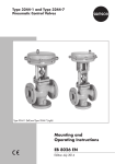
Type 3347-1 and Type 3347-7
Pneumatic Control Valves
Hollow-mold cast body
with welding ends
Bar stock body
with threaded connections
Fig. 1 · Type 3347-7 Control Valve with Type 3277 Actuator and integral positioner
Mounting and
Operating Instructions
EB 8097 EN
Edition June 2004
Contents
Contents
Page
1
Design and principle of operation. . . . . . . . . . . . . . . . . . . . 4
2
2.1
2.2
2.3
Assembling valve and actuator. . . . . . . . . . .
Assembly and adjustment . . . . . . . . . . . . .
Option to pretension the springs for actuator version
"Actuator stem extends" . . . . . . . . . . . . . .
Valve and actuator that have different rated travels.
3
3.1
3.2
Installation . . . . . . . . . . . . . . . . . . . . . . . . . . . . . . . 7
Mounting position. . . . . . . . . . . . . . . . . . . . . . . . . . . . 7
Signal pressure line . . . . . . . . . . . . . . . . . . . . . . . . . . . 8
4
Operation . . . . . . . . . . . . . . . . . . . . . . . . . . . . . . . 8
5
5.1
Maintenance . . . . . . . . . . . . . . . . . . . . . . . . . . . . . . 8
Replacing sealing parts or the plug . . . . . . . . . . . . . . . . . . . 9
6
Description of nameplates . . . . . . . . . . . . . . . . . . . . . . . 10
7
Customer inquiries . . . . . . . . . . . . . . . . . . . . . . . . . . 11
. . . . . . . . . . . 6
. . . . . . . . . . . 6
. . . . . . . . . . . 7
. . . . . . . . . . . 7
Note:
Non-electrical actuators and valves do not have their own potential ignition source
according to the risk assessment in the rare incident of an operating fault, corresponding to
EN 13463-1: 2001 paragraph 5.2, and therefore do not fall within the scope of the
European Directive 94/9/EC.
Refer to paragraph 6.3 of EN 60079-14:1977 VDE 0165 Part 1 concerning connection to
equipotential bonding system.
2
EB 8097 EN
Safety instructions
General safety instructions
4 The control valve may only be mounted, started up or serviced by fully
4
4
4
trained and qualified personnel, observing the accepted industry codes and
practices. Make sure employees or third persons are not exposed to any
danger. All safety instructions and warnings in these mounting and operating instructions, particularly those concerning assembly, start-up and maintenance, must be observed.
The control valves fulfill the requirements of the European Pressure Equipment Directive 97/23/EC. Valves with a CE marking have a declaration of
conformity that includes information about the applied conformity assessment procedure.
The corresponding declaration of conformity can be viewed and downloaded on the Internet at http://www.samson.de.
For appropriate operation, make sure that the control valve is only used in
areas where the operating pressure and temperatures do not exceed the operating values which are based on the valve sizing data submitted in the order. The manufacturer does not assume any responsibility for damage
caused by external forces or any other external influence! Any hazards
which could be caused in the control valve by the process medium, operating pressure, signal pressure or by moving parts are to be prevented by
means of the appropriate measures.
Proper shipping and appropriate storage of the control valve are assumed.
CAUTION!
4 For installation and maintenance work on the valve, make sure the relevant
4
4
section of the pipeline is depressurized and, depending on the process medium, drained as well. If necessary, allow the control valve to cool down or
warm up to reach ambient temperature prior to starting any work on the
valve.
Prior to performing any work on the valve, make sure the supply air and
control signal are disconnected or blocked to prevent any hazards that
could be caused by moving parts.
Special care is needed for pneumatic control valves when the actuator
springs are pretensioned. These actuators are labeled correspondingly and
can also be identified by three long bolts protruding from the bottom of the
actuator. Prior to starting any work on the control valve, relieve the compression from the pretensioned springs.
EB 8097 EN
3
Design and principle of operation
1
Design and principle of opera- Fail-safe position
tion
Depending on how the springs (8.3) are ar-
The Type 3347 Angle Valve can be combined with either a Type 3271 or a
Type 3277 Pneumatic Actuator with integral
positioner attachment.
The standard valve body is designed for
welding in pipelines. Further versions with
threaded, flange or clamp connections are
available as options.
The valve body and bonnet are connected
by an easy-to-use clamp. The body is designed free of cavities, making it suitable for
cleaning-in-place (CIP) procedures.
The control valves are primarily intended for
throttling or on-off service in the food processing industry.
The process medium flows through the valve
in the direction indicated by the arrow. The
position of the plug (3) is determined by
changes in the signal pressure acting on the
actuator diaphragm.
The stem connector (7) connects the plug
stem (6) with attached plug (3) and actuator
stem (8.1). The stems are sealed by PTFE
seals (5.1 and 5.3).
In the special version with connection to a
steam line, an additional spring-loaded
PTFE ring packing (4.2) is used to seal the
valve. The steam line connection can be
used to clean the plug stem.
4
EB 8097 EN
ranged in the actuator, the control valve assumes two different fail-safe positions:
Actuator stem extends
When the pressure is relieved or the supply
air fails, the actuator springs move the actuator stem downwards and close the valve.
The valve is opened against the force of the
springs when the signal pressure increases.
Actuator stem retracts
When the pressure is relieved or the supply
air fails, the actuator springs move the actuator stem upwards and open the valve.
The valve is closed against the force of the
springs when the signal pressure increases.
Design and principle of operation
Type 3271 Actuator
Type 3277 Actuator
8.3
8
8.2
8.1
6.1
6.2
7
5.5
5.3
8.1
5
8.2
6
5.4
5
5.2
1.3
3
1
1
1.1
1.2
1.3
3
4.1
4.2
4.3
5
5.1
5.2
5.3
5.4
9
8
Valve body
Centering ring
Body gasket
Compensation ring
Plug
Spring (spec. version)
Packing (spec. version)
Washers (spec. version)
Valve bonnet
Stem seal
Body and stem seal
Wiper
Clamp
5.5 Travel indicator
scale
6 Plug stem
6.1 Stem connector nut
6.2 Lock nut
7 Stem connector
8 Actuator
8.1 Actuator stem
8.2 Annular nut
8.3 Compression springs
9 Loading pressure
connection
10 Compression screw
fitting
Special version with connection
to a steam line
Version with hollow-mold cast body
10
4.2
5.1
5.4
1.2
1.1
6.2
6
5.3
4.3
4.1
4.3
3
1
Fig. 2 · Sectional drawings
EB 8097 EN
5
Assembling valve and actuator
2
Assembling valve and actuator
Instead of the simple pneumatic actuator, it
is also possible to attach an actuator with
additional handwheel or an electric actuator.
The standard pneumatic actuator can be replaced by a pneumatic actuator in a different size.
If the travel range of the actuator exceeds
that of the valve in the valve-actuator configuration, the manufacturer will adjust the
spring assembly of the actuator such that the
travels match.
2.1
Assembly and adjustment
If the valve and actuator have not been preassembled by the manufacturer or in the
case that the original actuator attached to
the valve is to be replaced by another actuator of a different type or size, proceed as
follows:
1. Loosen the lock nut (6.2) and stem connector nut (6.1) on the valve. Firmly
press the plug with the plug stem into
the seat. Then thread down the lock nut
and stem connector nut.
2. Remove clamps of the stem connector
(7) and annular nut (8.2) on the actuator (8).
Slide the annular nut over the plug stem.
3. Place the actuator on the valve bonnet
(5) and screw tight using the annular nut
(8.2).
4. Read the nameplate on the actuator to
determine which bench range (e.g. 0.2
to 1 bar or 0.4 to 2 bar) and which op-
6
EB 8097 EN
erating mode (e.g. "Actuator stem extends") are used.
The operating mode (fail-safe action) "Actuator stem extends" or "Actuator stem retracts" is indicated on the nameplate by FA
or FE on the Type 3271 Actuator and by the
appropriate symbol on the Type 3277 Actuator.
The lower bench range corresponds to the
lower signal pressure range to be adjusted;
the upper bench range corresponds to the
upper signal pressure range.
Note:
Make sure on assembling the valve
that the stem seal (5.1) does not get
damaged.
The maximum possible travel of the
actuator may not exceed the maximum permissible valve travel (see
adhesive label on the yoke).
5. For actuators with fail-safe action "Actuator stem extends", apply the pressure
corresponding to the lower signal pressure range (e.g. 0.2 or 0.4 bar) to the
loading pressure connection on the bottom diaphragm chamber.
For actuators with fail-safe action "Actuator stem retracts", apply the pressure
corresponding to the upper signal pressure range (e.g. 1 or 2 bar) to the loading pressure connection on the top diaphragm chamber.
6. Manually turn the stem connector nut
(6.1) until it touches the actuator stem
(8.1) and then turn it a further 1/4 turn.
Screw tight the lock nut.
Installation
7. Position clamps of the stem connector
(7) and fasten.
Align travel indicator scale (5.3) with tip
of the stem connector; for actuators with
"Actuator stem extends" align it with
lower marking (valve closed) and for actuators with "Actuator stem retracts"
align it with top marking (valve open).
Note concerning dismantling the actuator:
On dismantling an actuator with "Actuator
stem extends" and especially when an actuator has pretensioned springs, first apply
pressure slightly higher than the lower bench
range value (see nameplate on actuator) to
the loading pressure connection on the
bottom diaphragm chamber before
loosening the annular nut (8.2).
2.2
Option to pretension the
springs for actuator version
"Actuator stem extends"
To achieve a greater thrust, the springs of
actuators (350 and 700 cm2) can be
pretensioned by up to 25 % of their travel or
their bench range.
Example: If, with a bench range of 0.2 to 1
bar, the springs are to be pretensioned by
0.1 bar, for example, the bench range is
shifted by 0.1 bar, resulting in a new bench
range of 0.3 to 1.1 bar (0.1 bar corresponds to a compression of 12.5 %).
When adjusting the valve, a signal pressure
of 0.3 bar is to be set as the lower signal
pressure range.
The new bench range of 0.3 to 1.1 bar must
be marked on the nameplate as bench
range with pretensioned springs.
2.3
Valve and actuator that have
different rated travels
Note:
Valves that have a smaller travel than that of
the actuator must always use pretensioned
springs.
CAUTION!
Actuators with springs that have already
been pretensioned by the manufacturer
without attachment to a valve are marked by
an appropriate label.
In addition, such actuators can be identified
by three bolts and nuts protruding from the
bottom diaphragm case.
3
Installation
3.1
Mounting position
The valve must be installed upright with the
actuator on top.
Note:
Remove the clamp (5.4) first and take the
entire bonnet assembly off the valve body
before welding (valve version with welding
ends) in the pipeline.
Note:
Always install the valve free of stress. Check
that the plug stem moves smoothly.
Thoroughly flush out the pipeline before installing the valve.
EB 8097 EN
7
Operation
If the valve bonnet is designed with a connection for a steam line, connect the compression screw fittings to the steam supply
line.
CAUTION!
A higher pressure in the steam line
(steam or sterile fluid) than the pressure in the valve itself can affect the
process medium in the valve as it
may become mixed with the steam
(or sterile fluid).
Observe the relevant hygiene regulations.
3.2
Signal pressure line
Connect the signal pressure line for valves
with actuator version "Actuator stem extends" to the loading pressure connection on
the bottom diaphragm case, and for valves
with actuators "Actuator stem retracts" to the
loading pressure connection on the top diaphragm case.
The lower connection of Type 3277 Actuator
is located on the yoke of the bottom diaphragm case.
4
Operation
(e.g. reversing the direction of action, etc.)
For details, refer to the Mounting and Operating Instructions of the respective pneumatic
actuator.
EB 8310 EN for Type 3271 and
EB 8311 EN for Type 3277.
8
EB 8097 EN
5
Maintenance
If leakage occurs, this could be caused by a
damaged wiper (5.3) or stem seal (5.1) or
the PTFE V-ring packing (4.2) is defective in
the version with connection to a steam line.
If the valve does not seal properly, the tight
shut-off may be impeded by dirt or other impurities caught between the seat and plug,
or by damaged seat joints.
Remove the parts, clean them thoroughly
and replace them with new ones, if necessary.
Before servicing or disassembling the
control valve, depressurize the concerned section of the plant and drain
it.
Wait until the medium has cooled
down, if necessary.
As valves are not free of cavities,
there might still be residual medium
in the valve.
We recommend removing the valve
from the pipeline or remove the entire valve assembly when the valve is
welded in the pipeline.
On performing any work on the
valve body, first shut off the supply
pressure, disconnect the supply pressure line and remove the actuator.
On disassembling or assembling the
valve, make sure that the stem seal
does not get damaged.
Do not move the plug beyond the
permissible valve travel.
Maintenance
5.1
Replacing sealing parts or
the plug
Note:
Prior to performing any work on the valve
body, remove the actuator first.
1. Apply pressure higher than the lower
bench range (see nameplate) to the actuator.
2. Remove clamps of the stem connector
(7) between actuator stem and plug
stem and unscrew annular nut (8.2).
3. Lift the actuator off the valve.
4. Remove nuts (6.1 and 6.2).
5. Take off the clamp (5.4) and remove
carefully the valve bonnet (5) together
with plug (3) and centering ring (1.1).
6. Pull plug out of the valve bonnet, taking
particular care to prevent the stem seal
(5.1) from getting damaged.
7. Push out damaged parts such as wiper
(5.3) and stem seal (5.1) using an appropriate tool.
In the version with connection to a steam
line, additionally take out packing (4.2),
packing washers (4.3) and spring (4.1).
Clean the packing chamber.
8. Check that the surface of the plug stem
is highly polished and free of score
marks. If the stem surface is not flawless,
it must be repolished to ensure that the
stem seal cannot get damaged.
9. Apply a special lubricant to each new
part and the plug stem.
Contact your nearest SAMSON subsidiary or the SAMSON After-sales Service
department for information on suitable
lubricants.
10. Put the stem seal over the plug stem at
first in the opposite direction with lip towards the threaded end to stretch the lip
of the stem seal slightly.
Carefully pull off the stem seal again.
11. Slide a new centering ring (1.1) with
gasket (1.2) over the plug stem (not necessary with bar stock body version).
12. Carefully slide the stem seal, centering it
over the threaded end of the plug stem.
The stem seal must fit tightly, but slide
easily over the plug stem.
13. Insert the plug stem with stem seal and
centering ring (1.1), if applicable, into
the valve bonnet.
Slide the wiper (5.3) over the plug stem
into the valve bonnet.
14. Carefully place the valve bonnet onto
the valve body.
Carefully lubricate the clamp (5.4) as
well as the flange of the valve bonnet
and valve body.
15. Place the clamp (5.4) in position and
screw tight the clamp screw.
Hit the clamp lightly with a plastic hammer and tighten the clamp screw again.
Repeat this procedure several times to
tighten the clamp as far as it will go and
a leakproof body is achieved.
If, in the version with a steam line
connection, the valve bonnet is too light
to put the clamp back on, first slightly
press the packing springs together using
the valve bonnet.
EB 8097 EN
9
Description of nameplates
16. Thread the lock nut (6.2) and nut (6.1)
onto the plug stem (6).
17. Mount actuator and adjust the lower or
upper bench range as described in section 2.
6
Description of nameplates
2
1
3
0062
DN
4
10
SAMSON 3347
Made in France
Valve labeling, laser printed
5
Pmax20˚C=
KVS 8
6
Tmax= 7
Serial-No. 9
Nameplate of Type 3271 Actuator
SAMSON
H 5 F
1
6
2
3
V
4
7
1
2
3
4
5
6
7
8
Type designation with modification index
FDA compliance, if applicable
PED conformity, if applicable
Nominal size
Body material
Maximum pressure (bar or psi)
Maximum operating temperature (°C or °F)
Flow coefficient acc. to DIN or ANSI,
% = equal percentage, Lin = linear
9 Serial number
10 Year of manufacture
Nameplate of Type 3277 Actuator
SAMSON
Model - No.
1
Serial - No.
1
2
3
4
5
6
7
Type designation
Modification index
Effective diaphragm area
Operating mode:
For Type 3271:
FA Actuator stem extends
FE Actuator stem retracts
For Type 3277:
Left: Actuator stem extends
Right: Actuator stem retracts
Travel
Bench range (spring range)
Bench range with pretensioned springs
Fig. 3 · Nameplates
10
EB 8097 EN
Pneum. Stellantrieb
3
Pneum. actuator
Servo - monteur pneum.
Federbereich
Spring range
Plage des ressorts
Stelldruckbereich
Signal pressure range
Plage avec précontrainte
Hub
cm² Stroke
Course
mm
bar
bar
Zuluft max. 6 bar Begrenzt auf
Air supply 90 psi Up to
Air d' alimentation Limité à
Made in France
bar
Customer inquiries
7
Customer inquiries
Please submit the following details:
4 Type designation and serial number
4 Nominal size and version of the valve
4 Pressure and temperature of the process
medium
4 Flow rate in m³/h
4 Bench range of the actuator
(e.g. 0.2 to 1 bar)
4 Installation drawing
Dimensions
Refer to the Data Sheet T 8097 EN for the
dimensions and weights of the various valve
versions.
EB 8097 EN
11
EB 8097 EN
S/Z 2014-07
SAMSON AG ⋅ MESS- UND REGELTECHNIK
Weismüllerstraße 3 ⋅ 60314 Frankfurt am Main, Germany
Phone +49 69 4009-0 ⋅ Fax +49 69 4009-1507
Internet: http://www.samson.de