1
Self-operated Temperature Regulators
Safety Temperature Monitor (STM)
Type 2040
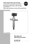
Fig. 1 · Type 2040 Safety Temperature Monitor
Mounting and
Operating Instructions
EB 2090 EN
Edition July 2010
Contents
Contents
Page
1
Design and principle of operation . . . . . . . . . . . . . . . . . . . 4
2
Installation . . . . . . . . . . . . . . . . . . . . . . . . . . . . . . . 6
3
3.1
3.2
Set point adjustment . . . . . . . . . . . . . . . . . . . . . . . . . . 6
New adjustment . . . . . . . . . . . . . . . . . . . . . . . . . . . . 7
Set point adjuster with set point indication . . . . . . . . . . . . . . . . 7
4
Maintenance . . . . . . . . . . . . . . . . . . . . . . . . . . . . . . 8
5
Service. . . . . . . . . . . . . . . . . . . . . . . . . . . . . . . . . 8
6
Dimensions . . . . . . . . . . . . . . . . . . . . . . . . . . . . . . 9
7
Technical data . . . . . . . . . . . . . . . . . . . . . . . . . . . . 10
8
Nameplate . . . . . . . . . . . . . . . . . . . . . . . . . . . . . . 11
Definitions of the signal words used in these instructions
CAUTION!
Indicates a hazardous situation which, if not
avoided, could result in minor or moderate
injury.
2
EB 2090 EN
Note! Indicates supplementary explanations,
information and tips.
Safety instructions
General safety instructions
4 The regulator may only be mounted, started up or operated by trained and
4
4
4
4
experienced personnel familiar with the product.
According to these mounting and operating instructions, trained personnel refers
to individuals who are able to judge the work they are assigned to and recognize
possible dangers due to their specialized training, their knowledge and
experience as well as their knowledge of the relevant standards.
All safety instructions and warnings in these mounting and operating instructions,
particularly those concerning assembly, start-up and maintenance, must be
observed.
For appropriate operation, make sure that the regulator is only used in
applications where the operating pressure and temperatures do not exceed the
operating values based on the sizing data submitted in the order.
Note that the manufacturer does not assume any responsibility for damage
caused by external forces or any other external factors.
Any hazards which could be caused in the regulator by the process medium or
operating pressure are to be prevented by means of appropriate measures.
The Type 2040 Safety Temperature Monitors do not have their own potential
ignition source according to the ignition risk assessment stipulated in
EN 13463-1: 2001, section 5.2, even in the rare incident of an operating fault.
Therefore, they do not fall within the scope of Directive 94/9/EC.
The regulator complies with the requirements of the European Pressure Equipment
Directive 97/23/EC. The declaration of conformity issued for a valve bearing the
CE marking includes information on the applied conformity assessment
procedure.
The declaration of conformity can be provided on request.
TÜV typetesting/EC type examination
The Type 2040 Safety Temperature Monitors are typetested by TÜV (German technical surveillance association). The test mark is available on request.
An EC type examination according to Pressure Equipment Directive 97/23/EC, Module B has
been performed on the Type 2040 Safety Temperature Monitor.
EB 2090 EN
3
Design and principle of operation
1
Design and principle of operation
The Type 2040 Safety Temperature Monitor
protects downstream plants against excessively low temperatures in applications involving the storage of cryogenic media as
well as liquids, gases and vapors.
These safety temperature monitors close
whenever the medium temperature falls below the adjusted temperature set point (limit)
to prevent cold media entering the connected
consumer plant.
The safety temperature monitor consists of the
body (1) with integrated temperature sensor
(6) and set point adjuster (3). It operates according to the liquid expansion principle.
The volume of the temperature-sensitive filling
medium confined in the integrated temperature sensor (6) expands as the temperature
rises and contracts again as the temperature
falls. The valve is normally open. If the medium temperature falls below the adjusted set
point (when the medium is too cold), the liquid inside the sensor contracts and the tubular
plug (5) is pushed by the positioning springs
(4) against the soft-sealed seat (2). As the medium temperature drops, the plug moves in
the closing direction, restricting the medium
flow. If the medium temperature drops further, the valve is closed completely when the
temperature reaches the adjusted set point.
The set point temperature and the throttling
range in front of it can be adjusted within the
set point range. The valve first opens again
when the medium temperature has exceeded
the adjusted set point by 2 K.
The temperature span between the adjusted
set point temperature Tset point and the point at
which the regulator starts to close is 17 K. The
valve is fully open (KV = 5) at a medium temperature of >Tset point + 17 K. At a medium
temperature less than Tset point + 17 K the medium flow is already throttled and the KV coefficient gets smaller (Fig. 2).
If the sensor system is defective, the valve
closes (fail-safe position).
Open
ΔT = 17 K temperature differential between
open and closed (throttling range)
Tset point = –20 °C (point at which the
regulator starts to close)
Normal range of
medium temperature
Closed
Fig. 2 · Control behavior
4
EB 2090 EN
–20
Tset point
–3
The regulator starts to close when the
medium temperature has dropped below a
value which is still approx. 17 K above the
adjusted set point.
Design and principle of operation
Connection nut with
soldering nipples (brass)
or welding ends
(stainless steel)
Connection nut with flat gasket · Connection with
soldering nipples (brass) or welding ends (stainless steel)
1
2
Body with connection
Valve seat with soft sealing
3
3.1
3.2
4
5
6
7
8
Set point adjuster
Cap
Lock nut
Positioning spring
Tubular plug
Temperature sensor
Connection nut with spherical liner (accessories)
Connection nut with flat gasket (accessories)
Fig. 3 · Functional diagram of Type 2040 Safety Temperature Monitor
EB 2090 EN
5
Installation
2
Installation
The following points generally apply:
Connection fittings (accessories) must be provided at the site of installation.
Note!
Do not install the regulator directly next to an
air vaporizer. Otherwise, the regulator could
close due to the low outdoor temperature. The
closing function of the regulator does not depend on whether the sensor temperature is
determined by the outdoor air or by the medium.
For outdoor installation, we recommend an
adjusted set point temperature of –37 °C together with the point at which the regulator
starts to close at –20 °C (set point range –45
to –10 °C).
4 The regulator can be installed in any desired position
4 The direction of flow must match the arrow on the valve body
3
Set point adjustment
See Figs. 3 and 4
The safety temperature monitor has been adjusted by the manufacturer to a set point temperature (limit) of Tset point = –10 °C (set point
range from –30 to +10 °C) or –37 °C (set
point range from –45 to –10 °C).
After removing the cap (3.1) and undoing the
lock nut (3.2), the required set point
temperature (Tset point) can be adjusted within
the set point range using the set point adjuster
(3).
Turns of the set
point adjuster
2.0
1.5
1.0
0.5
-30 -25 -20 -15 -10 -5
0.5
Tset point
0
5
10 [˚C]
1.0
1.5
2.0
Turns of the set
point adjuster
Fig. 4 · Adjustment diagram at a set point temperature Tset point = –10 °C (point at which regulator starts to close)
6
EB 2090 EN
Set point adjustment
Use the adjustment diagram (Fig. 4) as a
guide to change the set point temperature
from the default setting. One turn of the set
point adjuster corresponds to a change in set
point temperature of approx. 13 K.
The set point temperature together with the
point at which the regulator starts to close shift
to lower temperatures when the set point
adjuster (3) is turned clockwise P.
3.1
New adjustment
4 Secure setting, if necessary, with sealing
wire through the holes in the cap and
valve.
3.2
Set point adjuster with set
point indication
In a special version, the set point adjuster is
fitted with a marked ring for set point
indication. The distance between two marks
corresponds to a temperature difference of
approx. 10 K (10 °C).
Adjustment of the set point temperature from
an unknown setting:
Note! The ambient temperature must be
within the set point range.
4 Remove cap (3.1) and undo lock nut
4
4
4
4
4
(3.2). Make sure that the medium flow
and outside air have the same temperature.
Turn the set point adjuster (3) counterclockwise until the flow noise inside the
regulator ceases, i.e. the valve is closed.
Calculate the temperature difference between the momentary ambient
temperature and the required set point
temperature (Tset point) to be adjusted.
Divide the calculated temperature difference by 13. The result shows how may
turns of the set point adjuster (Fig. 4) are
required.
Turn the set point adjuster clockwise by
the determined number of turns.
Lock set point adjuster (3) with the lock
nut (3.2) and screw cap (3.2) back on.
EB 2090 EN
7
Maintenance
4
Maintenance
CAUTION!
Prior to performing any work on the regulators, decommission the plant by slowly closing the shut-off valves. Depressurize and, depending on the process medium, drain the
plant section as well.
CAUTION!
Regulators for oxygen service are labeled to
indicate that the regulators must be kept free
of oil and grease for oxygen service.
These versions are cleaned and assembled
under special conditions. Gloves must be
worn when exchanging parts which come
into contact to oxygen. These parts must not
come into contact with oil or grease.
When returning regulators for oxygen service
to SAMSON for repair, the sender is responsible for ensuring that the regulators are handled in conformance with the specifications in
the German regulation VBG 62 or equivalent
regulations until receipt at SAMSON. If this is
not the case, SAMSON AG will not assume
any responsibility for the suitability of these
regulators for oxygen service.
If the point at which the regulator closes deviates strongly from the adjusted set point, shutoff may be impaired because the seat and
plug are clogged up with dirt or due to natural wear.
In this case, remove the regulator from the
pipeline and clean it. If necessary, replace the
plug seal with a new one.
8
EB 2090 EN
5
Service
If malfunctions or defects occur, contact the
SAMSON After-sales Service for support.
The addresses of SAMSON AG, its subsidiaries, representatives and service facilities
worldwide can be found on the Internet at
www.samson.de, in a SAMSON product catalog or on the back of these mounting and
operating instructions.
Include the following details when making inquiries:
4 Type and nominal size of the regulator
4 Process medium
4 Set point temperature range
4 Production number 3- ...
4 Model number with modification index
4 Flow rate in m³/h
4 Installation drawing indicating the exact
location of the regulator (e.g. outdoors
or indoors) and all additionally mounted
units (shut-off valves, pressure gauges
etc.)
Dimensions
6
Dimensions
L1±1
L3 ±3
L2 ±1
L3 ±3
H1
133±1
133±1
ØD
Ød
ØD
Ød
H1
Connecting parts with flat gasket
Connecting parts with spherical liner
Soldering nipple (brass)
Dimensions in mm
L3
∅d
Welding ends (stainless steel)
DN 15
DN 25
100
For pipe ∅ 16
For pipe ∅ 28
Height H1
Without set point indication: H1 = 108±1 mm
With set point indication: H1 = 116±1 mm
Weight: 1.8 kg (without connecting parts)
Dimensions in mm
DN 15
DN 25
L1
155
L2
165
∅d
16.1
28.5
∅D
21.3
33.7
Fig. 5 · Dimensions
EB 2090 EN
9
Technical data
7
Technical data
Table 1 · Technical data · All pressures in bar (gauge)
Type 2040 Safety Temperature Monitor
Body connection
G 1¼ (see Fig. 4 for connecting parts)
5
KVS coefficient
Set point ranges
–30 °C to +10 °C
–45 °C to –10 °C 1)
Max. perm. operating pressure
40 bar
Max. perm. differential pressure Δp
25 bar
Leakage rate
≤ 0.05 % of KVS at –10 °C
≤ 0.1 % of KVS at –45 °C
Hysteresis
2K
Accuracy
±1 °C
Permissible temperature range
–60 °C to +60 °C
17 K
Temperature differential between open/closed
1) On request
Table 2 · Materials · Material number according to DIN EN
Type 2040 Safety Temperature Monitor
Body
CC491K (G-CuSn5ZnPb)
Bellows
CW453K (CuSn8F40)
Spring
1.4310
O-ring
NBR
CW617N (CuZn40Pb2)/NBR
Seat
Tubular plug
10
EB 2090 EN
1.4571/1.4404
Nameplate
8
Nameplate
Laser inscription on the regulator body
Set point temperature with unit
Flow of direction
Production number: 3- ...
Model number with modification index
Valve coefficient KVS = 5
Test mark 1)
Keep regulator free of oil and grease
1) Omitted at a set point temperature between –31 °C and –45 °C
Fig. 6 · Nameplate specifications
EB 2090 EN
11
EB 2090 EN
S/Z 2010-08
SAMSON AG · MESS- UND REGELTECHNIK
Weismüllerstraße 3 · 60314 Frankfurt am Main · Germany
Phone: +49 69 4009-0 · Fax: +49 69 4009-1507
Internet: http://www.samson.de