1
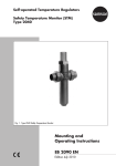
Electrohydraulic Actuators
Type 3274
Fig. 1 · Type 3274 Electrohydraulic Actuator
Mounting and
Operating Instructions
EB 8340 EN
Edition March 2012
Contents
Contents
1
1.1
Design and principle of operation. . . . . . . . . . . . . . . . . . . . 5
Versions . . . . . . . . . . . . . . . . . . . . . . . . . . . . . . . . 5
1.2
Principle of operation . . . . . . . . . . . . . . . . . . . . . . . . . . 6
1.3
Additional electric equipment . . . . . . . . . . . . . . . . . . . . . . 6
2
2.1
Installation . . . . . . . . . . . . . . . . . . . . . . . . . . . . . . . 8
Assembling the actuator and valve. . . . . . . . . . . . . . . . . . . . 8
3
Electrical connections . . . . . . . . . . . . . . . . . . . . . . . . . 10
4
4.1
Operation. . . . . . . . . . . . . . . . . . . . . . . . . . . . . . . 13
Override of the actuator . . . . . . . . . . . . . . . . . . . . . . . . 13
4.1.1
4.1.2
4.2
Version with electric override. . . . . . . . . . . . . . . . . . . . . . 13
Version with mechanical override . . . . . . . . . . . . . . . . . . . 15
Adjusting additional electric equipment. . . . . . . . . . . . . . . . . 15
4.2.1
4.2.2
4.2.3
4.2.4
Positioner . . . . .
Position transmitter
Potentiometer . . .
Limit contacts . . .
5
Dimensions in mm. . . . . . . . . . . . . . . . . . . . . . . . . . . 21
2
EB 8340 EN
.
.
.
.
.
.
.
.
.
.
.
.
.
.
.
.
.
.
.
.
.
.
.
.
.
.
.
.
.
.
.
.
.
.
.
.
.
.
.
.
.
.
.
.
.
.
.
.
.
.
.
.
.
.
.
.
.
.
.
.
.
.
.
.
.
.
.
.
.
.
.
.
.
.
.
.
.
.
.
.
.
.
.
.
.
.
.
.
.
.
.
.
.
.
.
.
.
.
.
.
.
.
.
.
15
18
19
19
Safety instructions
General safety instructions
For your own safety, follow these instructions concerning the mounting, start up and operation of the actuator:
4 The actuator may only be mounted, started up or operated by trained and
experienced personnel familiar with the product.
According to these Mounting and Operating Instructions, trained personnel
refers to individuals who are able to judge the work they are assigned to and
recognize possible dangers due to their specialized training, their knowledge
and experience as well as their knowledge of the relevant standards.
4 Any hazards that could be caused by the process medium, operating pressu-
re or by moving parts are to be prevented by means of the appropriate measures.
4 The actuator has been designed for use in low voltage installations.
4 During wiring and maintenance, you are required to observe the relevant safety regulations. Take necessary measures to ensure that the power supply
cannot be reconnected inadvertently.
4 Before connection, disconnect the power to the actuator.
To avoid damage to any equipment, the following also applies:
4 Proper shipping and appropriate storage are assumed.
EB 8340 EN
3
Technical data
Actuator
Type 3274
-11
-12
Version with override
-13
-14
-15
Electric
-16
-17
-18
-21
Mechanical
-22
Fail-safe action
With
Without
Operating direction
Rated travel
Extends
Retracts
Extends
15 or 30 mm
Rated actuating time
60 s with 15 mm · 120 s with 30 mm
depending on temperature and required actuating force
Actuating time for
fail-safe action [mm/s]
Actuating
force (N)
with
-23
Electric
normal
–
optional
Stem retracts 2100
500
4300
500
2100
500
4300
500
1
1
3.3
3.3
1.3
5
2100
1800
500
15 mm
travel:
Stem extends 2000 3400 4300 7700 2000 3400 4300 7700 2000 2300 3400
30 mm
travel:
Stem extends 1800 3000 4300 7300 1800 3000 4300 7300 1800 2100 3000
Stem retracts 2100
500
4300
500
2100
500
4300
500
2100
1800
500
230 V, 110 V, 24 V, 50 or 60 Hz (both ±10 %)
Power supply
Power consumption
with power supply
24 V, 110 V, 230 V/50 Hz
24 V, 110 V, 230 V/60 Hz
110 V, 230 V/50 Hz with faster motor
110 V, 230 V/60 Hz with faster motor
Positioner
Permissible ambient temperature
90 VA
110 VA
150 VA
185 VA
3 VA
–10 to +60 °C · With heating resistor: –35 to +60 °C
Storage temperature
–25 to +70 °C
Electromagnetic compatibility
Complying with EN 61326-1, EN 61000-6-2 and EN 61000-6-3
Degree of protection
IP 65 according to EN 60529
Weight
Approx. kg
12
15
12
Additional electrical equipment
Positioner
Power supply
230 V, 110 V, 24 V; 50 or 60 Hz (both ±10 %)
Control signal
4(0) to 20 mA (Ri = 50 W) · 0(2) to 10 V (Ri = 10 kW)
Zero shift
0 to 100 %
Change of span
30 to 100 %
0(4) to 20 mA, RB £ 200 W · 0(2) to 10 V, RB £ 2 kW
Output (feedback)
Hysteresis
Approx. 3 %
0 to 1000 W, 0 to 200 W, 0 to 100 W, 0 to 275 W, 0 to 138 W
(when rated travel is 80 % of final value), permissible load 0.5 W
Potentiometers
Electric limit contacts
Maximum three separately adjustable limit contacts, 250 V AC, 5 A
Inductive limit contacts
Proximity switch SJ 2-N (NC contacts only)
Control circuit
Heating resistor, approx. 45 W
Values according to downstream isolating amplifier
With thermostat, activated at –10 °C, deactivated at approx. 0 °C
Materials
Housing, cover
Die-cast
aluminum
4
EB 8340 EN
Cylinder
Piston
Piston rod
Actuator stem
Hydraulic oil
Hydraulic
cylinder tube
Steel/NBR
combination
C 45, hard
chrome plating
1.4104
Special HPL,
silicone-free
Design and principle of operation
1
Design and
operation
principle
of
The electrohydraulic actuators are especially
suitable for attachment to SAMSON Series
240, 250 and 280 Valves.
The actuators are connected to the valve
bonnet by a ring nut. The actuator and plug
stem are tightly connected by a stem connector. The actuator essentially consists of
the actuator housing, the motor including oil
pump as well as the cylinder housing with
piston.
Pilot valves control the supply and discharge
of the compressed oil at the piston. The actuator is equipped with compression springs
which determine the positioning forces. Actuator versions with spring mechanism also
serve to move valve to the fail-safe position
“Actuator stem retracts“ or “Actuator stem
extends“ in the event of a power supply
failure.
1.1
Versions
The following versions are available for different applications:
Versions with electric override
Type 3274-11 · Electrohydraulic actuator
with an actuating force Fretracts of 2100 N in
direction of action “Actuator stem retracts”
and an actuating force Fextends of 1800 N in
direction of action “Actuator stem extends”
Type 3274-12 · Electrohydraulic actuator
with actuating forces Fretracts of 500 N and
Fextends of 3000 N
Type 3274-13 · Electrohydraulic actuator
with actuating forces Fretracts and Fextends of
4300 N
Type 3274-14 · Electrohydraulic actuator
with actuating forces Fretracts of 500 N and
Fretracts of 7300 N.
Versions with mechanical override
These versions have a mechanical override
instead of an electric override.
Type 3274-15 · Electrohydraulic actuator
with same actuating forces as Type 3274-11
Type 3274-16 · Electrohydraulic actuator
with same actuating forces as Type 3274-12
Type 3274-17 · Electrohydraulic actuator
with same actuating forces as Type 3274-13
Type 3274-18 · Electrohydraulic actuator
with same actuating forces as Type 3274-14
Versions with fail-safe action and electric
override
Type 3274-21 · Electrohydraulic actuator
with actuating force Fretracts of 2100 N and
Fextends of 1800 N.
Fail-safe action: “Actuator stem extends”
Type 3274-22 · Electrohydraulic actuator
with actuating force Fretracts of 1800 N and
Fextends of 2100 N.
Fail-safe action: “Actuator stem retracts”
Type 3274-23 · Electrohydraulic actuator
with actuating force Fretracts of 500 N and
Fextends of 3000 N.
Fail-safe action: “Actuator stem extends”
Typetesting
The Type 3274-21 and Type 3247-23 Actuators are typetested with various
SAMSON valves by TÜV according to
DIN EN 14597.
See the nameplate for the DIN register
number.
EB 8340 EN
5
Design and principle of operation
1.2
Principle of operation
The pressure-tight actuator housing (1)
(Fig. 2) also serves as the oil reservoir and
incorporates the cylinder housing (2), cylinder (5.1) and piston (5.2), motor (6.1),
pump (6.2) and solenoid pilot valves (6.4).
The oil pump (6.2) driven by the motor (6.1)
feeds compressed oil to the corresponding
cylinder chamber over the check valve (6.3)
and pilot valve (6.4). The solenoid valves
are closed in the de-energized state. They
open when the controller issues an output
signal. When reaching a final position or
when the actuating force is exceeded due to
external forces, the motor is switched off.
Depending on the version, the actuators are
equipped without compression springs or
with one or two compression springs (5.7,
5.8). The motor of Types 3274-11, -12,
-15, -16 and -21 to -23 only determine the
valve position in one direction, while the
springs are used to return the valve to its
fail-safe position.
Actuators with electric override have two
pushbuttons to extend or retract the actuator
stem.
Actuators with mechanical override have an
extra gear housing. An Allen key must be
inserted to activate the override function. In
combination with a release button on the top
of the actuator housing, the actuator stem
can be extended or retracted.
Versions with fail-safe action have a spring
return mechanism and an additional safety
solenoid valve which opens when the power
supply is interrupted, reducing the pressure
on the cylinder chamber. The spring return
6
EB 8340 EN
mechanism moves the valve to the fail-safe
position.
1.3
Additional electric equipment
All additional electric equipment are located
in the terminal box (3). A rack-and-pinion
gear converts the linear travel of the actuator stem into a rotary motion which is picked
off at the shaft to operate the switching and
signaling elements. Additional electric
equipment can be retrofitted. The maximum
equipment configuration is shown in the table in section 4.2.
Electric positioner
The positioner compares the 4(0) to 20 mA
or 0(2) to 10 V signal issued by a controller
to the signal issued by a potentiometer. The
potentiometer signal is proportional to the
travel. The output variable produced by the
positioner is a three-point stepping control
signal.
Position transmitter
In the version with three-point stepping signal, an 0(4) to 20 mA or 0(2) to 10 V output signal is generated proportional to the
travel of the valve using a 0 to 1000 W potentiometer.
Potentiometer
The actuators can be equipped with two potentiometers. A gear segment is driven by a
shaft. An easily adjustable transmission
mechanism including a twin pinion ensures
that the angle of rotation remains the same
for rated travels of 15 and 30 mm.
Electric limit contacts
The actuators can be equipped with a maximum of three overrideable electric switches
Design and principle of operation
on request. They are actuated by infinitely
adjustable cams. The motor is switched off
with force-dependent, fixed switches located
in the actuator housing (1).
Actuators with spring return mechanism only
contain one force-dependent switch since
the springs (5.7 and 5.8) determine the
other end position.
with two resistors by the manufacturer. The
heating is activated by thermostats when the
oil temperature falls below –10 °C and deactivated when the oil reaches a temperature of 0 °C. The electrical connection is established at N and L. The heating is not protected by an internal fuse.
Priority circuit
The positioner version is equipped with a
priority circuit at terminals 82 and 83 (see
section 4.2.1).
Heating
For lower ambient temperature ranges, the
oil reservoir can be equipped with a heating
1
6.4
3
6.3
6.2
5.2
6.1
5.1
2
5.7
5.8
NOTICE
The housing cover is secured by leaded screws.
All parts in the actuator housing are maintenance-free and must not be tampered with.
Do not open the housing!
5.4
5.6
1
1.1
2
3
3.1
4.3
4.4
5.1
5.2
5.10
5.11
6.1
6.2
6.3
6.4
Actuator housing and oil reservoir
Housing cover
Cylinder housing
Terminal box
Cover
Limit contact (extending)
Limit contact (retracting)
Cylinder
Piston
Compression spring
Compression spring
Motor
Oil pump
Check valve
Pilot valve
Fig. 2 · Functional diagram
EB 8340 EN
7
Installation
2
2.1
Installation
Mounting position: To meet the mounting requirements of actuators with heating and/or
manual override, the following mounting positions should be observed.
Assembling the actuator and
valve
If the actuator has not been mounted on the
valve prior to delivery, proceed as follows
(see Fig. 4):
Not permissible
Permissible
Permissible
Not permissible
Check whether the actuator stem is retracted.
For versions with electric override:
4 Connect actuator to power supply (see
section 3).
4 Disconnect isolating terminal 81 (see section 4.1) and use pushbutton IN to retract the actuator stem.
Fig. 3 · Mounting positions
The installation of the actuator also depends
on the mounting position of the control valve
used (see the associated mounting and operating instructions).
For valve sizes DN 100 or above, install the
actuator upright to facilitate any maintenance required.
Always observe minimum clearance for removal of the cover or the complete actuator
(see dimensional drawings, section 5).
For versions with mechanical override:
4 Press button on the top of the actuator
housing.
4 Use an Allen key to operate the
rack-and-pinion gear and slowly retract
the actuator stem.
For versions with fail-safe action "Actuator
stem extends", keep the power supply to the
actuator connected, otherwise the fail-safe
function will extend the actuator stem again.
DN 15 to 80 (Series 240)
1. Replace stem connector nut (9.3, Fig. 4)
with an external Ø 10 mm on the plug
stem with a Ø 16 mm nut (order no.
0250-0674).
2. After replacing the stem connector nut
(9.3), adjust dimension x to 75 mm with
a closed valve and tighten lock nut (9.4).
3. Place the actuator on the valve bonnet,
fasten tight using the ring nut (8.1).
4. Push plug stem (9.5) upward. Connect
stem connector nut (9.3) and actuator
8
EB 8340 EN
Installation
stem using the stem connector clamps
(8.2).
5. Move the valve to its end position and
align travel indicator scale (9.2) with the
tip of the stem connector.
DN 100 to 150 (Series 240 as well as Series 250 and 280, KVS 40 to 160)
1. Check that dimension x = 90 mm, readjust, if necessary, by turning the stem
connector nut (9.3).
2. Place the actuator on the valve bonnet
and fasten tightly using the ring nut
(8.1).
3. Connect stem connector nut (9.3) and
actuator stem (5.6) using the stem connector clamps (8.2), fasten together
tightly.
4. Move the valve to its end position, align
travel indicator scale (9.2) with tip of the
stem connector (8.2) and screw tight.
8
8.1
5.6
8.2
9.3
9.4
x
9.2
9.1
8
8.1
5.6
8.2
9.1
9.2
9.3
9.4
9.5
Actuator
Ring nut
Actuator stem
Stem connector
Valve bonnet
Travel indicator scale
Stem connector nut
Lock nut
Plug stem
9.5
Fig. 4 · Attachment to the actuator
EB 8340 EN
9
Electrical connections
3
Electrical connections
Risk of electric shock!
When installing electric lines, you
are required to observe the regulations governing electrical power
plant installation according to DIN
VDE 0100 as well as the regulations
of your local power supply company.
CAUTION!
Use a suitable power supply which
guarantees that no dangerous voltages reach the device in normal operation or in case of a fault in the
system or any other system parts.
Connect the actuator to the electrical
network only after the power supply
is first switched off.
Make sure the power cannot be
switched on unintentionally!
Particularly for 24 V, 50 Hz actuators, use wires with a sufficiently
large cross section in order to guarantee that the permissible voltage
tolerances of ±10 % are not
exceeded.
Note:
When electrical connections are made as
described in the circuit diagrams, special
electronics in the motor ensure that the contacts of controller's output relays (e.g. with
controllers for three-point stepping signal)
are protected and only a relatively low
power load is used.
A triac and a relay in the motor electronics
connect the power.
10
EB 8340 EN
4 Unfasten the side housing cover. Guide
the wires through the cable glands on the
housing to the terminals and connect
them (see Figs. 5 to 7 or the circuit diagram inside the housing cover).
Knock out the sealing plugs next to the existing cable entries, if required, to use two additional cable entries.
4 Connect safety conductor to the separate
safety conductor terminal on the inside
housing wall.
Electrical additional equipment
Circuit diagrams 5 to 7 also apply to the additional equipment.
Note that the limit contacts must not be connected to the terminal strip but to separate
screw terminals.
In the version with positioner (Fig. 6) and
position transmitter (Fig. 7), output signals
which are proportional to the valve travel
can be provided at the terminals 31, 32, 33
to be used for control and signaling purposes (signal increases when the actuator
stem retracts).
NOTICE
When a device is connected at the voltage
output, terminals 31 and 32 must be
jumpered.
Fuses
The board with the electronics section of the
motor contains a clamp with a 5 x 20 mm
glass-tube fuse which is used to protect the
actuator and the contacts of the external
controller when the actuator is wired as
shown in Figs. 5 to 7.
Electrical connections
Supply voltage
230 V, 50/60 Hz T1L 250 (1 A slow fuse)
2
F
e
Retracts
F
a
ϑ
N
L
aL
3274-11...-18,-21,-23
M
3274-13,-14,-17,-18,-22
Heating resistor
Actuators with a transit time of 60 s for
30 mm travel:
230 V, 50 Hz T1.25, 250 (1.25 slow fuse)
110 V, 50 Hz T1.25 (1.25 A slow fuse)
24 V, 50 Hz T6.3 (6.3 A slow fuse)
eL a43 e53
"e"
e
81
a
e
1.311.321.33 2.312.32 2.33
Safety circuit, only
with Type 3274-2x
N
4
"a"
a
Controller
PE
1
Extends
NOTICE
The controller output relay to control the aL
and eL input signals for the actuator must
only be connected to terminal 81 (same
equipotential bonding)
L
Fig. 5 · Circuit diagram for actuators with three-point stepping signal
EB 8340 EN
11
F
e
F
a
J
N
2
L
aL
3274-11...-18,-21,-23
M
3274-13,-14,-17,-18,-22
Heating resistor
Electrical connections
Retracts
e
a
"e"
eL a43 e53 82 83
81
"a"
12 11 13 32 31 33 2.312.32 2.33
+
+
(0)4...20 mA (0)4...20 mA
green
brown
N
Bridge with 0(2)-10 V
Feedback essential
white
+
(0)2...10V
Safety circuit, only
with Type 3274-2x
PE
4
1
Extends
+
(0)2...10V
Output
Input
control signal (feedback)
L
F
e
F
a
J
N
L
aL
2
Retracts
3274-11...-18,-21,-23
M
3274-13,-14,-17,-18,-22
Heating resistor
Fig. 6 · Circuit diagram for actuators with positioner
eL a43 e53 82 83
Extends
"a"
a
81
Controller
N
L
Safety circuit, only
with Type 3274-2x
Fig. 7 · Circuit diagram for actuators with position transmitter
12
EB 8340 EN
e
12 11 13 32 31 33 2.312.32 2.33
+
(0)4...20 mA
PE
4
1
"e"
+
(0)2...10V
Output
Bridge with 0(2)-10 V
Feedback essential
Operation
4
Operation
If the controller signal must have priority
again, proceed as follows:
4.1
Override of the actuator
1. Switch off power. Remove housing
cover.
2. Firmly press release button until it engages so that the red marking pin becomes visible.
3. Reattach housing cover using screws.
Switch on power.
4.1.1 Version with electric override
Type 3274-11 to -14 and -22, -23
The actuator stem can be either retracted or
extended by pressing one of the two
pushbuttons located on the side cover. In this
way, the attached valve can be brought into
the required position.
After releasing the button, the actuator uses
the controller signal again.
NOTICE
If, e.g. upon start-up of the plant, the control
signal is to be interrupted and the control
valve is to remain in a certain position, the
isolating terminal 81 must be disconnected
(Fig. 8).
For this purpose, proceed as follows:
1. Switch off power.
2. Loosen the two fastening screws on the
side housing cover and remove cover.
3. Place screwdriver under the release button of the isolating terminal 81 and lever
up button until it engages. The red marking pin is not visible.
4. Reattach cover with screws.
5. Switch on power.
The control signal is now interrupted and the
valve can be moved to the desired position
by using the two pushbuttons IN and OUT.
The valve will then remain in the adjusted
position.
EB 8340 EN
13
Operation
13
1
2
3
4
12
1
2
3
4
5
6
7
8
9
10
11
12
13
Fuse
Motor electronics
Adjuster for version
with positioner
Segment gear
Push rod
Release button
Marking pin
Isolating terminal
Pushbutton OUT
Pushbutton IN
Potentiometer
Limit contact(s)
Series switches for
version with positioner
5
11
6
10
Isolating terminal
7
Red marking pin
8
Release button
9
Disconnect
isolating terminal
Fig. 8 · Terminal box with adjuster controls
14
EB 8340 EN
Connect isolating
terminal
Operation
4.1.2 Version with mechanical
override
4.2
Adjusting additional electric
equipment
1. Press black release button located on the
top of the actuator housing.
2. Use an Allen key to operate the
rack-and-pinion gear at the end of the
shaft, projecting out of the housing, until
you have moved the valve to the desired
position.
As soon as the button is released, the actuator operates according to the controller signal again.
The actuators can be equipped with different
combinations of additional electric equipment. Such equipment can also be retrofitted.
If the valve is to remain in the manually adjusted position, the isolating terminal 81
must be disconnected as described in section
4.1.1.
Positioner
The maximum equipment configuration is
shown in the vertical columns of the table
below.
Additional electric equipment
• •
Positioner
• •
Potentiometer 1
• • • • • • • •
Potentiometer 2
• • • • • •
Electric contact 1
Actuator stem
retracts
100%
<>
<<
Travel
Actuator stem
extends
0%
4
20 mA
• •
Electric contact 2
•
•
•
•
•
Electric contact 3
•
•
•
•
•
Inductive contact 1
•
•
•
•
•
Inductive contact 2
•
•
•
•
•
1)
1000 W, required for position feedback
to positioner/position transmitter
4.2.1 Positioner
100%
<>
Split-range
operation
The actuator is controlled by a load-independent DC current or DC voltage signal
which is used as reference variable w.
<<
Valve 1 and 2
operating in
opposite directions
0%
Fig. 9 · Characteristic
4
12
Dead band
20 mA
The valve travel must also be assigned to this
reference variable, normally a signal in the
range from 4 to 20 (0 to 20) mA or 2 to 10
(0 to 10) V, see Fig. 9).
In the split-range mode, the control valves
use smaller reference variables. The control-
EB 8340 EN
15
Operation
ler output signal used to control two valves is
divided in such a way that these valves
move through their entire travel range each
at half of the input signal range (for example, first control valve adjusted to 12 to
4 mA and second control valve to 12 to
20 mA.
If the contact at terminals 82 and 83 is
open, the valve position is determined by the
controller signal again.
Note for split-range mode:
To prevent the valves from overlapping
when they are being adjusted, a dead band
as shown in Fig. 9, for example, ± 0.5 mA
should be taken into account. Valve 1 would
then be set from 11.5 to 4 mA and Valve 2
from 12.5 to 20 mA, the corresponding values also apply for V input signals.
SW 2 set to ON <> Actuator stem extends
when the reference variable increases.
Adjuster controls
SW 3 and 4 set to OFF – 0 to 20 mA or
0 to 10 V
The adjuster controls (Fig. 10) are located
on the cover plate of the electronics unit. To
access them, unthread the two screws on the
side housing cover and remove the cover.
The mechanical fail-safe action is not affected by the priority circuit used in the actuators.
Operating direction – SW 2
SW 2 set to OFF >> Actuator stem retracts
when the reference variable increases.
Output signal – SW 3 and 4
Depending on the signal connected to terminals 31, 32 and 33
SW 3 and 4 set to ON – 4 to 20 mA or
2 to 10 V
Note: Both switches SW 3 and SW 4 must
be in the same position!
CAUTION!
The actuator is energized!
Adjusters
on
The following functions can be selected at
the switch block SW by using the individual
switches SW 1 to 4.
off
1
Priority circuit – SW 1
If an external contact connected to terminals
82 and 83 is closed, the actuator moves the
valve to its end position regardless of the input signal as follows:
SW 1 set to ON · Actuator stem retracts
SW 1 set to OFF · Actuator stem extends.
40
Starting point
(zero)
EB 8340 EN
Span
in
80
100
Output signal
Position feedback
Fig. 10 · Adjuster controls
16
4
Span
out
Zero
in
60
20
3
2
Final value
(span)
Operation
Adjustment at the valve
Operating direction >>:
The following description refers to a globe
valve which closes when the actuator stem
extends and to a three-way valve which provides tight closure of two ports.
7. Set switch SW 2 to OFF.
Initial setting:
(required for both operating directions >>
and <>)
Segment for
15 mm travel
Segment for
30 mm travel
15
1. Open isolating terminal 81 by pulling up
the release button (Fig. 8).
2. Use the manual override to move the
valve to the lower end position, i.e. the
actuator stem must be extended as far as
it will go into the valve seat. With an
electric override, press the + button, with
a mechanical override, operate the
rack-and-pinion gear (section 4.1.2).
3. Turn the associated gear segment
around its axis according to the nominal
travel of the valve (15 or 30 mm) until
the marking arrow is above the point
where the gears mesh (Fig. 11).
4. Hold the gear segment and the gear in
this position. Then use a screwdriver to
turn the axis of the feedback potentiometer P1 to the right as far as it will go.
5. Select output signal for valve position indication at the switches SW 3 and
SW 4.
6. Connect a suitable current or voltage
source (or controller) to the input signal
terminals (reference variable w).
Connect an ammeter for valve position
indication to the terminals 31, 32.
8. Set input signal to the starting point
(4 mA) at the current source.
9. Slowly turn Zero adjuster clockwise until
the LED turns off and then continue to
turn it slightly until the LED lights up
again. This causes the maximum closing
force to be produced in the valve.
10. Use manual override to move the valve
to the upper end position, i.e. retract the
actuator stem.
11. Set input signal at the current source to
the final value (20 mA).
12. Turn Span out adjuster until the ammeter
indicates an output signal of 20 mA
30
The reference variable selected, e.g. 4 to
20 mA.
Turn Zero adjuster counterclockwise as far
as it will go (0 %) and turn Span in adjuster
to the mid position (mark).
P1
Position of marking
arrow when push rod
is extended to the
maximum
P2
Potentiometer
Feedback potentiometer 0 to 1000 W with version
with positioner and position transmitter
Fig. 11 · Travel adjustment
EB 8340 EN
17
Operation
13. Turn Span in adjuster all the way
counterclockwise. Then slowly turn it
back to the point where the LED just
turns off (when a globe valve is open).
Continue turning in the same direction a
little bit more until the LED lights up
again (when the second port of a
three-way valve is closed) in order to
produce maximum closing forces.
14. If you do not want to change the operating direction to <>, close isolating terminal 81 by pressing the release button.
Operating direction <>
15. Set switch SW 2 to ON. Turn Zero adjuster clockwise as far as it will go
(100 %).
16. Set input signal to starting point 4 mA
again.
17. Slowly turn Zero adjuster counterclockwise to the point where the LED turns off
(when a globe valve is open). Then turn
slightly in the same direction until the
LED just lights up again (when the second port of a three-way valve is closed)
in order tor produce maximum closing
forces.
Do not operate any other adjuster afterwards!
18. Close isolating terminal 81 by pressing
the release button.
18
EB 8340 EN
Note:
The positioner can also be used as a "mere
position transmitter".
To proceed, remove the wires that lead from
the positioner case to the terminals aL and
eL and strip the insulation off the free wire
ends. Then connect the wires of the external
three-point stepping signal (controller) to the
terminals aL, eL and 81.
The terminals 11, 12 and 13 as well as the
priority circuit no longer function.
4.2.2 Position transmitter
1. Select the output signal for position
transmitter at switch SW 3 and SW 4.
SW 3 and 4 to ON = 4 to 20 mA or
2 to 10 V
SW 3 and 4 to OFF = 0 to 20 mA or
0 to 10 V.
2. Connect an ammeter to terminals 31, 32
or, after jumpering the terminals 32 and
31, connect a voltmeter to terminals 32
and 33 to indicate the valve position.
3. Move the valve to the lower end position, i.e. the actuator stem must be extended as far it will go into the valve seat
using the manual override (section 4.1).
4. Turn the associated gear segment
around its axis according to the nominal
travel of the control valve (15 or 30 mm)
until the marking arrow is above the
point where the gears mesh (Fig. 11).
5. Hold the gear segment and the gear in
this position. Then use a screwdriver to
turn the axis of the feedback potentiometer P1 clockwise as far as it will go.
6. Turn potentiometer P1 in the opposite direction until the required initial value of
Operation
the output signal is indicated on the
measuring instrument.
7. Open the control valve, the final value of
the output signal should be indicated on
the measuring instrument. If the value is
incorrect, readjust the final value correspondingly at the Span out adjuster.
The feedback signal increases as the actuator stem retracts. If a signal with decreasing characteristic is required, reverse the white and green connecting
wires at the potentiometer.
4.2.3 Potentiometer
The actuator can be equipped with either
one or two potentiometers (Fig. 11), depending on its version. Actuators equipped
with a positioner require a potentiometer
(P1) for internal valve position feedback. Its
resistance value cannot be used for external
signaling purposes.
Potentiometer P1
1. Extend actuator stem all the way into the
valve.
2. Depending on the nominal travel of the
valve, turn gear segment 15 or 30 mm
on its axis until the marking arrow is
above the point where the gears mesh
(Fig. 11).
3. Hold gear segment and gear in this position. Then use a screwdriver to turn the
axis of the potentiometer P1 clockwise
as far as it will go.
Potentiometer P2
This potentiometer is driven by the pinion of
potentiometer P1. Opposed resistance values arise.
Adjust potentiometer as described for P1,
however, turn axis counterclockwise as far
as it will go while holding the gear segment
and the gear.
4.2.4 Limit contacts
The switching point of the additional limit
contacts (Fig. 12) is infinitely adjustable
within the travel range.
Electrical limit contact
4 Move control valve to the desired switch-
ing position, turn adjustment screw until
the operating cam contacts the roller and
reverses the microswitch. If necessary,
move actuator in opposite direction,
check whether the cam reaches the
switching point at the desired switching
position.
Inductive limit contact
When using inductive contacts, isolating amplifiers must be connected in the output circuit according to EN 50227.
4 Move control valve to the desired switching position. Turn adjustment screw until
the metal tag triggers the contact.
EB 8340 EN
19
Operation
Operating cam
Roller
Switch
(covered)
Metal tag
Proximity switch
Adjustment screw
Adjustment screw
Fig. 12 · Electric (left) and inductive (right) limit contacts
20
EB 8340 EN
Clamping screw
Dimensions in mm
.
Type 3274-... with
mechanical override
.
75 for 15 mm travel
Dimensions in mm
75 for 15 mm travel
90 with 30 mm travel
5
.
.
Type 3274-... with
electric override
EB 8340 EN
21
22
EB 8340 EN
EB 8340 EN
23
EB 8340 EN
2012-03
SAMSON AG · MESS- UND REGELTECHNIK
Weismüllerstraße 3 · 60314 Frankfurt am Main · Germany
Phone: +49 69 4009-0 · Fax: +49 69 4009-1507
Internet: http://www.samson.de