1
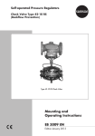
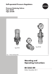
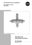
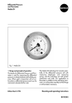
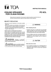
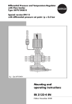
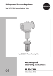
Excess Pressure Valves Type 44-7 and Type 44-8 (SEV) Fig. 1 · Type 44-7 Excess Pressure Valve (DN 40) Mounting and Operating Instructions EB 2723 EN Edition September 2007 Contents Contents Page 1 Design and principle of operation . . . . . . . . . . . . . . . . . . . . 4 2 2.1 2.2 2.3 Installation . . . . . . . . . . . Mounting position . . . . . . . . Strainer . . . . . . . . . . . . . Additional installation instructions . . . . . . . . . . . . . . . . . . . . . . . . . . . . . . . . . . . . . . . . . . . . . . . . . . . . . . . . . . . . . . . . . . . . . . . . . . . . . . . . 6 6 6 6 3 3.1 3.2 3.3 Operation . . . . . Start-up. . . . . . . Set point adjustment. Shut-down . . . . . . . . . . . . . . . . . . . . . . . . . . . . . . . . . . . . . . . . . . . . . . . . . . . . . . . . . . . . . . . . . . . . . . . . . . . . . . . . . . . . . 6 6 7 7 4 4.1 4.2 Maintenance . . . . . . . . . . . . . . . . . . . . . . . . . . . . . . 7 Cleaning or replacing the plug. . . . . . . . . . . . . . . . . . . . . . 7 Replacing the diaphragm . . . . . . . . . . . . . . . . . . . . . . . . 8 5 Nameplate . . . . . . . . . . . . . . . . . . . . . . . . . . . . . . . 9 6 Customer inquiries . . . . . . . . . . . . . . . . . . . . . . . . . . . 9 7 Dimensions and weights. . . . . . . . . . . . . . . . . . . . . . . . 10 . . . . . . . . . . . . . . . . . . . . . . . . Note: These Mounting and Operating Instructions EB 2723 EN refer to the Type 44-7 and Type 44-8 Excess Pressure Valves manufactured from August 2005 onwards (0085, see nameplate). Note: Non-electric actuators and control valve versions do not have their own potential ignition source according to the ignition risk assessment stipulated in EN 13463-1: 2001, section 5.2, even in the rare incident of an operating fault. Therefore, they do not fall within the scope of Directive 94/9/EC. For connection to the equipotential bonding system, observe the requirements specified in EN 60079-14: 1977 (VDE 0165 Part 1) section 6.3. 2 EB 2723 EN General safety instructions General safety instructions 4 The excess pressure valve must be installed, started up and serviced only by skilled or semi-skilled staff in accordance with good engineering practice so that employees and third persons are not exposed to danger. All safety instructions and warnings given in these mounting and operating instructions, particularly those concerning installation, start-up and maintenance, must be strictly observed. 4 The valve complies with the requirements of the European Pressure Equipment Directive 97/23/EC. The declaration of conformity issued for a valve bearing the CE marking includes information on the applied conformity assessment procedure and will be provided on request. 4 To ensure appropriate use, only use the valve in applications where the operating pressure and temperatures do not exceed the operating values specified in the order. 4 Note that the manufacturer does not assume any responsibility for damage caused by external forces or any other external factors. Take appropriate safety precautions to prevent hazards that may be caused in the valve by the process medium, operating pressure or moving parts. 4 Make sure the valve is shipped and stored properly. EB 2723 EN 3 Design and principle of operation 1 Design and principle of operation The excess pressure valve is typically used in district heating plants and large heating systems to maintain a constant desired upstream pressure. Increasing upstream pressure will cause the valve to open. The Type 44-7 and Type 44-8 Excess Pressure Valves consist of a valve body with a balanced valve plug and an actuator with an operating diaphragm and a spring assembly. The Type 44-8 is designed as a safety excess pressure valve (SEV). It incorporates a second diaphragm to ensure continued, safe operation of the valve even upon failure of the operating diaphragm. If the upstream pressure exceeds a specified high value, the safety excess pressure valve will fail open. Table 1 · Tightening torques Observe the tightening torques listed below when assembling the valve upon replacement of the plug or the diaphragm. Item Description 1.1 Body stopper 13 Body screws 2 Seat ring 15 Diaphragm plate nut 11 Control line connection 4 EB 2723 EN Nominal size Torque DN 15 to 25 70 Nm DN 32 to 50 110 Nm DN 15 to 32 8 Nm DN 40 to 50 18 Nm DN 15 to 25 110 Nm DN 40 to 50 110 Nm DN 15 to 25 40 Nm DN 15 to 50 80 Nm DN 15 to 50 22 Nm The medium flows through the valve in the direction indicated by the arrow on the valve body. The upstream (excess) pressure to be controlled passes through the control line (11) and flows into the area above the operating diaphragm (6.1). It acts on the operating diaphragm, producing a positioning force. This force is used to position the valve plug against the force of the spring assembly. Turning the set point adjuster (10) will change the spring force and the set point. Type test The safety excess pressure valves (SEV) have been typetested by the German Technical Inspectorate (TÜV). Type test approval numbers are available on request. Design and principle of operation 1.1 3.2 1 2 3.1 3.3 p1 3.3 3 3.4 3.6 p2 3 3.4 3.5 6.2 6.1 11 5 15 12 DN 15 to 25, plug assembly 14 + Turned into plane of projection 1.1 17 6 1 13 7 3 8 p1 p2 9 10 2 Type 44-8 SEV (DN 32 to 50), with threaded body 11 6.1 1 1.1 Valve body Body stopper 2 3 3.1 3.2 3.3 3.4 3.5 3.6 6 6.1 6.2 7 8 9 Seat ring Plug assembly Valve plug Plug nut Plug stem Plug spring Plug stopper Guide nipple Actuator housing Operating diaphragm Safety diaphragm Actuator stem Spring assembly Spring plate + 6 Turned into plane of projection 17 Type 44-7 (DN 32 to 50), with flanged body 10 11 12 13 14 15 16 17 Set point adjuster Control line Diaphragm rupture indicator (Type 44-8 only) Body screws Intermediate ring Diaphragm plate nut Diaphragm plate O-ring Fig. 2 · Sectional drawings of Type 44-8 and Type 44-7 EB 2723 EN 5 Installation 2 Installation 2.1 Mounting position 4 Install the valve in a horizontal pipeline with the actuator and spring assembly suspended downwards. 4 Make sure that the medium flows through the valve in the direction indicated by the arrow on the valve body. 4 Use the connection nuts included in the delivery to install the valve. 2.2 Strainer Note: Do not connect a strainer upstream of the Type 44-8 SEV. Install a strainer (e.g. SAMSON Type 1 NI) upstream of the Type 44-7 Valve to prevent sealing particles, weld spatter and other impurities carried along by the process medium from impairing the proper operation, especially the tight shut-off of the valve. 1 1 2 3 4 5 2 3 4 Hand-operated shut-off valve Upstream pressure gauge Strainer (for Type 44-7 only) Excess pressure valve Downstream pressure gauge Fig. 3 · Installation example 6 EB 2723 EN 5 1 Make sure that the medium flow corresponds with the direction indicated by the arrow on the strainer body. Install the strainer with the filter element suspended downwards. Ensure that enough space is available to remove the filter. 2.3 Additional installation instructions Ideally, hand-operated shut-off valves should be installed both upstream of the strainer and downstream of the excess pressure valve. They allow the pipeline section to be shut down for cleaning and maintenance routines or when it is not operated for long periods of time. Moreover, a plant shutdown will relieve the operating diaphragms. To monitor the pressures prevailing in the plant, install pressure gauges both upstream and downstream of the valve. 3 Operation 3.1 Start-up Fill the plant very slowly on start-up. First open the shut-off valve downstream of the excess pressure valve and then the shut-off valve upstream of the excess pressure valve. When carrying out a pressure test on the section of the pipeline equipped with the pressure regulator, make sure that the diaphragm actuator cannot be damaged by the test pressure. To proceed, remove the control line connected to the valve and seal the open port with a stopper (accessories: stopper 8323-0030 and seal 8412-0771). Maintenance If the upstream pressure drops considerably, tight shut-off is impaired by dirt between the Adjust the desired upstream (excess) pressure seat and plug or due to natural wear. by means of the set point adjuster (10) of the For Type 44-8 (SEV–two diaphragms) only: spring plate (9), monitoring the upstream If the operating diaphragm fails (6.1), the pressure indicated by the pressure gauge. safety diaphragm (6.2) will take over the Turn the set point adjuster clockwise to incontrol function. Simultaneously, a red markcrease the set point pressure. ing appears in the diaphragm rupture indiTurn the set point adjuster counterclockcator (12) (response at approx. 1.5 bar), or wise to decrease the set point pressure. medium will leak from the test connection of the actuator. Replace the defective operating diaphragm 3.3 Shut down (6.1). 3.2 Set point adjustment 4 4 First close the shut-off valve upstream of the valve and then close the shut-off valve downstream of the valve. 4 If the actuator stem leaks, disassemble the actuator as described in section 4.2. Inspect the actuator stem for any grooves and replace the O-rings (17) located in the actuator housing with new ones. Maintenance The valve is subject to natural wear. Depending on the application conditions that prevail, inspect the valve at appropriately scheduled intervals. CAUTION! Prior to carrying out any work, always depressurize the relevant section and drain it depending on the medium. First allow the relevant section of the plant to cool down to ambient temperature if high temperatures prevail. We recommend that the valve be removed from the pipeline for carrying out any work on the valve. When controlling freezing media, protect the regulator against frost. 4.1 Cleaning or replacing the plug – Refer to Fig. 1 on page 5 – CAUTION! The positioning springs are pre-tensioned. Take appropriate safety precautions. If necessary, make an appropriate disassembly tool or use SAMSON disassembly tool (order no. 1280-3098). 1. Remove the valve from the pipeline. Unscrew the control line (11). Disassemble the spring assembly (8) using a suitable tool (e.g. SAMSON disassembly tool 1280-3098). EB 2723 EN 7 Maintenance 2. Unscrew the body stopper (1.1). 3. Unfasten the body screws (13). Remove the actuator housing (6) with intermediate ring (14). 4. Unscrew the plug nut (3.2). Remove the valve plug (3.1) from the plug stem. 5. For DN 15 to 25 Unscrew the guide nipple (3.6) of the plug assembly (3) using the socket wrench (order no. 1280-3001) and pull it out. You can make this wrench from a GEDORE screwdriver bit (IN 19-19), for example, by drilling a 17 mm hole (Ø 17) into the 19 mm hexagon bit. 4.2 Replacing the diaphragm – Refer to Fig. 1 on page 5 – CAUTION! The positioning springs are pre-tensioned. Take appropriate safety precautions. If necessary, make an appropriate disassembly tool or use the SAMSON disassembly tool (order no. 1280-3098). 1. Remove the valve from the pipeline. 2. Unscrew the control line (11). Disassemble the spring assembly (8) using an appropriate tool (e.g. SAMSON disassembly tool 1280-3098). For DN 32 to 50 First unscrew the plug stopper (3.5), then pull out the plug assembly (3). 3. Unfasten the body screws (13). Remove the actuator housing (6) with intermediate ring (14). 6. Thoroughly clean the seat and plug assembly (3) and replace parts, if damaged. Check the control line (11) for any blockages. If the seat ring (2) is damaged, unscrew it and replace it with a new one. 4. Unscrew the diaphragm plate nut (15) and remove it from the actuator stem (7). Then lift off the diaphragm plate (16). 7. Reassemble the valve in reverse order of the steps above, observing the tightening torques specified in Table 1 on page 4. 8 EB 2723 EN 5. Replace the diaphragm(s). 6. For reassembly, proceed in reverse order, observing the tightening torques as indicated in Table 1 on page 4. Nameplate 5 Nameplate 1 6 2 Ü 4 6 10 8 If malfunctions or defects occur, contact the SAMSON After-sales Service for support. 3 7 9 1 Model number 2 Configuration ID 3 Date of manufacture 4 Type designation 5 Nominal pressure PN or ANSI Class 6 7 KVS or CV coefficient Max. perm. temperature in °C or °F 8 Set point range in bar or psi 9 Max. perm. differential pressure Dp 10 Arrow indicating direction of flow Fig. 4 · Nameplate Customer inquiries The address of SAMSON AG, its subsidiaries, representatives and service facilities worldwide can be found on the Internet at www.samson.de, in a SAMSON product catalog or on the back of these mounting and operating instructions. Should you have any inquiries, please submit the following details: 4 Type, nominal size of the valve and its set point range 4 Order and model numbers (see nameplate) 4 Upstream and downstream pressures 4 Temperature and process medium 4 Min. and max. flow rates 4 Has a strainer been installed? 4 Installation drawing with exact location of the regulator and all additional installed components (shut-off valves, pressure gauge, etc.) EB 2723 EN 9 Dimensions and weights 7 Dimensions and weights Dimensions in mm and weights in kg Standard version with connection nuts with welding ends Nominal size DN 15 20 25 32 40 Pipe diameter Ø d 21.3 26.8 33.7 42 48 50 60 Connection R G¾ G1 G 1¼ G 1¾ G2 G 2½ Width across flats SW 30 36 46 59 65 82 Length L 65 70 75 100 110 130 234 244 268 294 L1 with welding ends Dimension H Dimension H1 Weight, approx. in kg 210 330 Type 44-7 230 250 380 Type 44-8 235 255 395 Type 44-7 41 Type 44-8 2.0 58 2.1 2.2 3.5 9.0 9.5 Version with flanged body (DN 32, 40, 50) Length L3 130 150 160 180 200 Weight, approx. in kg 3.5 4.1 4.7 11.7 13 Special version with threaded ends (male thread) Length L2 129 144 159 180 196 228 Male thread A G½ G¾ G1 G 1¼ G 1½ G2 Weight, approx. in kg 2.0 2.1 2.2 8.5 9.0 9.5 10 EB 2723 EN Dimensions and weights Dimensions L1 L SW SW L1 L H1 H1 R d R d ~36 H H Ø116 (Ø160) Ø116 (Ø160) Type 44-7 Type 44-8 Standard version with connection nuts with welding ends (specifications in parentheses for DN 40/50) L3 Types of connection A L2 SW With connection nuts with threaded ends Flanged body (DN 32 to 50 only) Fig. 5 · Dimensional drawings EB 2723 EN 11 EB 2723 EN S/Z 2011-10 SAMSON AG · MESS- UND REGELTECHNIK Weismüllerstraße 3 · 60314 Frankfurt am Main · Germany Phone: +49 69 4009-0 · Fax: +49 69 4009-1507 Internet: http://www.samson.de Conversion from chromate coating to iridescent passivation Conversion from chromate coating to iridescent passivation We at SAMSON are converting the surface treatment of passivated steel parts in our production. As a result, you may receive a device assembled from parts that have been subjected to different surface treatment methods. This means that the surfaces of some parts show different reflections. Parts can have an iridescent yellow or silver color. This has no effect on corrosion protection. For further information, go to u www.samson.de/chrome-en.html