1
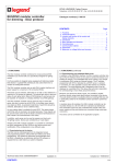
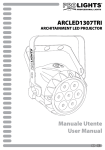
Installation and Operating Instructions
INSTABUS DALI gateway REG-K/1/16/64
Art. no. 680129
General
The INSTABUS DALI gateway brings the lighting control specfic
DALI-Bus and the pluridisciplinary and cross-functional EIB/KNX
bus together. Cost effective DALI ECGs can therefore be seamlessly integrated into an overall EIB/KNX architecture. DALI installations can benefit from the vast range of EIB/KNX user interfaces,
sensors and building control devices available today. The DALI
gateway serves both as DALI-Master device and power supply to
all connected ECGs. Up to 64 ECGs allocated to up to 16 different
groups can be connected per single DALI gateway. Additionally, up
to 16 lighting scenes can be created from the different groups. The
light intensities and failure warnings are available as status objects
and can be visualized using any corresponding EIB/KNX display
device. The commissioning of the DALI gateway (allocation of DALI
ECGs to the various groups) is performed using the programming
buttons and the display directly on the device. The setting of the
different parameters and the programming of the scenes can also
be perfomed with the buttons and the display, or alternatively using
ETS. Scenes that have already been programmed can subsequently be changed at any time on the device. Finally, in addition to
the EIB/KNX and the DALI interface, there are two binary inputs
available on the device for connecting conventional switches,
pushbuttons or movement sensors. This allows commissioning,
test and operation of the DALI ECGs without the connection of the
device to the EIB/KNX network.
PWR
SCROLL
Prg/Set
>2s
ESC
ERR
DALI-Gateway REG-K/1/16/64
AC 110-240V
50-60Hz
The DALI gateway is a 6 units wide DIN Rail mounted device. The EIB/KNX connector is a standard EIB/KNX BUS connector. The DALI
bus, the mains power and the binary inputs are fixed using screw connectors.
Device Type and Accessories
The following devices and accessories of this product group are available:
INSTABUS DALI gateway REG-K/1/16/64
Art. no. 680129
Package Contents
The delivery package of the INSTABUS DALI gateway REG-K/1/16/64 contains the following components:
•
•
•
Device with connected bus connector
1x shrink sleeve 1,2 x 2cm for supplementary insulation of the bus wires
Installation and Operating Instructions
Application Programs
Currently the following application programs are available for this device:
DaliControl 7303/1.0
Please refer to the application description for detailed information on the application program functionality.
Merten GmbH & Co. KG
1/10
Installation and Operating Instructions
INSTABUS DALI gateway REG-K/1/16/64
Art. no. 680129
Technical Data
Power Supplies
•
Mains Connector for 110 to 240 V, 50 to 60Hz, max. 0,1A
•
Additional Power Supply via the EIB Bus
Operating Elements
•
Programming Button to toggle between normal and addressing mode
•
3 buttons (SCROLL, Prg/Set, ESC) on display front to commission the device and set parameters
Display Elements
•
Red LED to indicate EIB/KNX Normal-/Addressing Mode
•
Green PWR-LED to signal device readiness (blinks when in normal operation mode)
•
Red ERR-LED to signal fault status
•
LC-Display, 2 lines with 12 characters each with menu for commissioning and setting of parameters.
Inputs
•
2 x passive binary input for connection of conventional pushbutton or movement sensor
9-32VDC or 8-26VAC, max wire length 15m
DALI-Bus
•
Connection of up to 64 ECGs complying to IEC 60926
•
DALI-Voltage 18-21VDC, short circuit proof
•
It is not allowed to use other control devices (DALI-Master devices) within the same line.
Connectors
•
EIB bus connector
•
Mains Connector: screw connector 3x 1,5mm² single or threaded core
•
DALI-Bus: screw connector 2x 1,5mm² single or threaded core
•
Binary input: screw connector 2x 1,5mm² single or threaded core
Mechanical Data
•
Casing: Plastic LEXAN UL-94-V0
•
Measurements of casing:
Width: 106mm
Height: 55mm
Length: 86mm
•
Weight:
200 g
•
Mounting: on 35mm DIN rail
Electrical Safety
•
Pollution Degree:
•
Protection (EN 60529):
•
Protection Class: (IEC 1140)
•
Overvoltage Category:
•
Bus: SELV DC 24 V
2
IP20
I
III
EMC-Compliance
Complies with EN 50090-2-2, EN 61000-6-2, EN 61000-6-3
Environmental
•
Operating Temperature: 0°C to +45°C
•
Storage Temperature: -25°C to +70°C
•
Rel. Humidity (non condensing): 5 % to 93 %
Certification
KNX/EIB registered
CE-Signage
According to EMC recommendations (domestic and commercial buildings), low voltage recommendations
Merten GmbH & Co. KG
2/10
Installation and Operating Instructions
INSTABUS DALI gateway REG-K/1/16/64
Art. no. 680129
Location and Function of the Control and Display Elements
The connectors as well as the KNX/EIB programming button and LED are only accessible once the cover of the distribution panel removed.
The operation of the programming buttons (SCROLL, Prg/Set, ESC), the control LEDs (PWR and ERR) as well as the menu display are accessible even with closed cover.
D+ D-
B1 B1 B2 B2
DALI CONTROL
SC 16, V.1.0
LED Prog.
At the lower side of the casing the following connectors can be found (left to right):
At the upper side of the casing the following connectors can be found (left to right):
On the device front the following elements can be found:
PE L N
A1:
A2:
A3:
A4:
A5:
A6:
A7:
A8:
A9:
A10:
A11:
A12:
A13:
EIB bus connector
EIB Programming LED
EIB Programming Button
Mains Connector
DALI-connector
Connector passive binary input 1
Connector passive binary input 2
Display 2x12 chars for DALI
Commissioning
SCROLL-button
Prg/Set-button
ESC-button
Operating-LED (PWR)
Failure-LED (ERR)
The signage of the connectors on the casing is to be followed at all times!
Installation Notices and Warnings
• Life Hazard through Electrical Shock
• The device must only be installed and commissioned by qualified Electricians!
• The current country specific safety and accident prevention rules and regulations as well as the EIB guidelines must be respected at all
times!
• The device is destined for fixed mounting in dry interior locations!
• When connecting the mains wires, the mains power must be switched off.
• The device must not be opened. Defectuous devices must be returned to the manufacturer.
Merten GmbH & Co. KG
3/10
Installation and Operating Instructions
INSTABUS DALI gateway REG-K/1/16/64
Art. no. 680129
Mounting and Connection
The INSTABUS DALI gateway REG-K/1/16/64
is designed to be mounted within distribution
panels equipped with 35mm DIN rails. After
simply snapping the device onto the rail, the
DALI bus should be connected first. The DALI
Control wires can be part of a 5-stranded cable
also carrying the ECG power accroding to
IEC90929 (the base insulation is sufficient).
However each wire must be clearly marked and
reliably identified. The maximum cable length
for one entire DALI segment must not exceed
300m.
After connecting the DALI control wires, the optional external pushbuttons can be connected.
The binary inputs are passive meaning that an
auxiliary 8-26VAC or 9-32V DC voltage is required to operate the switches.
It is now possible to connect the 110-240 VAC
50/60 Hz mains wires to the lower right connector block according to the printed schema.
The EIB bus cable is connected using the featured bus connector that is already inserted in
the block when the device is shipped. For
proper insulation from the power block, it is
necessary to wrap the EIB control wires from
the cable end right to the EIB connector with the
shrink sleeve that is part of the package.
After complete connection of the device and activation of the mains power, the device will display its product name and the firmware version. The blinking green PWR light signals that the device is ready. If the device is started without being connected to the EIB and as long
as no corresponding EIB application program has been downloaded, the red ERR-LED is lit. If the red ERR-LED is still ON after connecting
the EIB (fed with its EIB power supply) and after download of the application program, a short circuit within the DALI segment is the probable error source (refer Submenu SYSTEM TEST). Please check the wiring of the DALI segment in such cases.
Merten GmbH & Co. KG
4/10
Installation and Operating Instructions
INSTABUS DALI gateway REG-K/1/16/64
Art. no. 680129
Operation and Menu Structure
The connected DALI segment can entirely be commissioned with the three programming buttons (SCROLL, Prg/Set, ESC). Optional DALI
parameters can also be set or changed with these buttons. The usage is menu driven. Depending on the current menu position, up to two
submenu levels can be accessed. The currently selected menu item is shown in the display. The user navigates within the menu with short
pushes of the buttons: the SCROLL button selects the next menu item within each level. A short push on the Prg/Set button selects the
submenu, if it exists. The ESC button quits the current menu level and returns to the parent menu item.
Main Menu – Level 1
The main menu is structured as follows:
DALI CONTROL
SC 16, V.1.0
NEW
INSTALLATION
POST
INSTALLATION
GROUP
ASSIGNMENTS
GROUP
PARAMETERS
SCENE
ASSIGNMENTS
GROUP
TEST
TEST
SCENES
SYSTEM
TEST
The product description and the firmware version are displayed. This screen features a submenu that allows to select
the display language.
This screen features submenus which will reset all connected DALI ECGs and will start an automatic detection of
connected devices. This is the preferred choice for a new installation.
This screen features submenus that allow to resynchronize DALI ECGs after a post install (adding or removing ECGs
to a previously configured DALI gateway) by starting an automatic detection and displaying the modified configuration.
Within the submenus of this screen, the detected ECGs can be allocated to the desired DALI groups.
Within the submenus of this screen, the parameters of each group can be set and modified.
The submenus of this screen allow to add DALI groups to DALI scenes.
The submenus of this screen allow to switch the entire DALI segment (Broadcast) or individual DALI groups for testing purposes.
This screen features submenus to invoke individual DALI scenes for testing purposes.
This screens leads to submenus that will display all existing system failures individually.
FUNCTION
INPUT B1
The submenus of this screen allow to set the function of the binary input B1.
FUNCTION
INPUT B2
The submenus of this screen allow to set the function of the binary input B2.
Merten GmbH & Co. KG
5/10
Installation and Operating Instructions
INSTABUS DALI gateway REG-K/1/16/64
Art. no. 680129
If a function is to be activated or a parameter to be changed within a given submenu, it is necessary to switch to the so called programming
mode by pushing the Prg/Set button for more than 2 seconds. Once the selected function of parameter is in programming mode, an Arrow
symbol (→) appears in the display. Once the programming mode is active, the SCROLL button is used to change the setting or the parameter value. By pressing the Prg/Set button with a short push again, the programming mode is ended (EXIT and SAVE). The parameter is updated to the selected value or the selected function is activated. The ESC button quits the programming mode without saving.
Submenu DALI CONTROL – Level 2
DALI CONTROL
SC 16, V.1.0
SPRACHE
DEUTSCH
The level 1 menu DALI CONTROL leads to the submenu SPRACHE (LANGUAGE) by pressing the Prg/Set key
with a short push.
The currently active language is displayed within the submenu. By pressing the Prg/Set button for more than 2 seconds, the programming mode is activated. The SCROLL button navigates through the available languages:
DEUTSCH, ENGLISCH (English), FRANZÖS. (Français), SPANISCH (Español), SCHWEDISCH (Svenska). Pressing the Prg/Set button with a short push this time, the new language is activated and the display changes accordingly. The default language on shipment is GERMAN.
Submenu NEW INSTALLATION – Level 2
NEW
INSTALLATION
SEARCH ECG
via P-MODE
FOUND
ECGs: 47
A short push on the Prg/Set key leads from level 1 menu NEW INSTALLATION to the submenu SEARCH ECG via
P-MODE.
A long push of the Prg/Set button switches the device to programming mode. Another push, but a short one this
time, starts the initialisation and search processes. First, all ECGs connected to this DALI Segment are reset automatically, all previously assigned groups and parameters are deleted. Secondly, all ECGs are searched for by their
randomly generated long address and identified in ascending order.
The search process can require several minutes depending on the number of connected ECGs. After completion of
the search process, the number of discovered ECGs is shown on the display. By pushing the ESC button or by
simply waiting for more than 30 seconds, the parent menu item is again activated.
Submenu POST INSTALLATION – Level 2
POST
INSTALLATION
SEARCH ECG
via P-MODE
DELETED
ECGs: 3
NEW
ECGs: 1
DEL./NEW
ECGs: 3/1
A short push on the Prg/Set key leads from level 1 menu POST INSTALLATION to the submenu SEARCH ECG via
P-MODE.
A long push of the Prg/Set button switches the device to programming mode. Another push, but a short one this
time, starts the verification and search process. The connected ECGs are searched for by their long addresses.
The result is compared with the previous configuration. If ECGs have been removed from the DALI-Segment, their
corresponding entries and settings are automatically deleted from the DALI gateway. During the verification process, the number of deleted ECGs is summarized on the display.
The Gateway then searches for new ECGs within the DALI-Segment. New ECGs are automatically reset and all
previously assigned parameters are deleted. The search process can require several minutes depending on the
number of connected ECGs. During the search process, the number of new ECGs that are discovered is summarized on the display.
After completion of the verification and of the search process, the number of deleted and new ECGs are shown on
the display (# deleted ECGs on the left / # new ECGs on the right). By pushing the ESC button or by simply waiting
for more than 30 seconds, the parent menu item is again activated.
Merten GmbH & Co. KG
6/10
Installation and Operating Instructions
INSTABUS DALI gateway REG-K/1/16/64
Art. no. 680129
Submenu GROUP ASSIGNMENT – Level 2 and 3
GROUP
ASSIGNMENT
ECG Nr.: 12
GROUP:
--
ECG Nr.: 12
GROUP: 1
A short push on the Prg/Set key leads from level 1 menu GROUP ASSIGNMENT to a submenu allowing to assign
ECGs to one of the 16 DALI groups. Within the submenu, it is possible to create new assignments for ECGs or to
modify existing ones.
A short push on the SCROLL button navigates from one ECG to the next. The first display line shows the number
of the selected ECG. The corresponding light will blink for as long as its ECG is selected. This allows to easily identify which number is assigned to which light.
A long push of the Prg/Set button switches the device to programming mode. A short push on the SCROLL-Button
allows to select the group to which the ECG is to be assigned. Once the assignment completed, a short push on
the Prg/Set button will confirm and save the selection. For a new installation, this task needs to be completed for
each ECG that was discovered during the search process. By pushing the ESC button or by simply waiting for more
than 30 seconds, the parent menu item is again activated.
Submenu GROUP PARAMETERS – Level 2 and 3
GROUP
PARAMETERS
GROUP: 01
PARAMETERS
A short push on the Prg/Set key leads from level 1 menu GROUP PARAMETERS to a submenu allowing to set all
parameters of a DALI Group. It is recommended to set the group parameters within ETS and only use this function
for quick modification of individual settings. Please note that each ETS download overwrites these manual settings.
A short push of the SCROLL button navigates from one group to the next. The first display line indicates the current
group number. A long push of the Prg/Set button switches the device to programming mode and the parameter
type and its value are shown on the second display line. The following parameters can be modified directly on the
device:
•
•
•
•
GROUP: 12
ON VALUE: 100
GROUP: 12
MIN VAL: 0
GROUP: 12
MAX VAL: 100
GROUP: 12
DURATION: 10s
Initial (ON) Value:
Lower Dimming Limit (MIN VAL):
Upper Dimming Limit (MAX VAL):
Dimming Duration for 0..100%:
0 to 100% in 5% steps
0 to 40% in 5% steps
50 to 100% in 5% steps
5 sec. to 60 sec.
Once the programming mode is active, the first parameter (ON VALUE) is displayed. The parameter value can be
changed with a short push of the SCROLL button. If no change is required, don’t use the SCROLL button. A short
push of the Prg/Set button saves the parameter value and jumps to the next parameter of this group (MIN VAL)
which can in turn be modified or not. A short push again of the Prg/Set button saves the parameter value and jumps
to the next parameter of this group (MAX VAL) which can in turn be modified or not. And finally another short push
of the Prg/Set button saves the parameter value and jumps to the next parameter of this group (DURATION) which
can in turn be modified or not. A short push of the Prg/Set button saves the value and jumps again to the first parameter (ON VALUE). It is possible to escape back to the next higher menu with the ESC button or by simply waiting for more than 30 seconds.
Submenu SCENE ASSIGNMENT – Level 2 and 3
SCENE
ASSIGNMENT
SCENE01 XXXX
XXXXXXXXXXXX
SCENE03 ---XXXX------XX
A short push on the Prg/Set key leads from level 1 menu SCENE ASSIGNMENT to a submenu allowing to associate DALI Groups to up to 16 DALI Scenes.
With a short push of the SCROLL button, it is possible to navigate from one scene to the next. The first display line
shows the number of the currently selected scene. Symbols show which of the 16 groups are associated with this
scene. An ‘X’ at the corresponding location means that the group is part of the scene, a ‘–’ means that it is not. The
four characters following the scene number represent groups 1 through 4, the 12 characters on line two represent
groups 5 through 16.
A long push of the Prg/Set button switches the device to programming mode. A blinking cursor on the first X shows
that Group 1 is currently selected. A short push of the SCROLL button toggles between selected (‘X’) and not selected (‘–’). A short push of the Prg/Set button moves the cursor to the next Group field, which in turn can be selected or not with the SCROLL button, etc. Once all 16 Groups have been moved through, the configuration is
saved and immediately active. After completion of the last group, this submenu is closed automatically and the device returns to the next higher menu item. To avoid saving changes, don’t complete the line, and use the ESC button instead, or simply wait for more than 30 seconds.
Merten GmbH & Co. KG
7/10
Installation and Operating Instructions
INSTABUS DALI gateway REG-K/1/16/64
Art. no. 680129
Submenu GROUP TEST – Level 2 and 3
GROUP
TEST
GROUP: 6
TEST
GROUP: 6
->off
A short push on the Prg/Set key leads from level 1 menu GROUP TEST to a submenu allowing to switch individual
DALI Groups or all DALI Groups (via broadcast) at the same time for testing purposes.
A short push on the SCROLL button within the submenu allows to navigate from one group to the next. The currently active group is shown on the first display line.
A long push on the Prg/Set button switches the device to programming mode. A short push on the SCROLL button
sets the desired action (options ->on or ->off), which then needs to be commited with a short push on the
Prg/Set button. Pushing the ESC button or simply waiting for more than 30 seconds cancels the operation and
leads back to the parent menu item.
Submenu TEST SCENES – Level 2 and 3
TEST SCENES
SCENE: 2
TEST
SCENE: 2
->invoke
A short push on the Prg/Set key leads from level 1 menu TEST SCENES to a submenu allowing to switch individual
DALI scenes for testing purposes or to save current lighting settings to a given scene number.
A short push on the SCROLL button navigates from one scene to the next. The currently active scene is shown on
the first display line.
A long push on the Prg/Set button switches the device to programming mode. A short push on the SCROLL button
sets the desired action (options ->invoke or ->save scene), which then needs to be committed with a short push
on the Prg/Set button. Pushing the ESC button or simply waiting for more than 30 seconds cancels the operation
and leads back to the parent menu item.
Submenu SYSTEM TEST – Level 2 and 3
SYSTEM
TEST
DALI
fault
A short push on the Prg/Set key leads from level 1 menu SYSTEM TEST to a submenu allowing to view individual
failure messages.
It is clearly shown on the display if there are failures or not. The following failure types are recognized and shown
on the display and also signaled by the red failure LED (ERR):
•
•
•
•
LAMP
fault:L 23
ECG
fault:E 34
EIB
fault
Short circuit on the DALI bus
Lamp failure with indication of the ECG number
ECG failure with indication of the ECG number
EIB Bus not present
A short circuit on the DALI bus is a failure that prevents the device from recognizing any other failure that may be
present. By contrast, all other failure types are detected simultaneously. With a short push on the SCROLL button,
it is possible to navigate from one failure message to the next. Lamp and ECG failures show the ECG number, so
that the error can be located immediately within the group. Pushing the ESC button or simply waiting for more than
30 seconds leads back to the parent menu item.
Merten GmbH & Co. KG
8/10
Installation and Operating Instructions
INSTABUS DALI gateway REG-K/1/16/64
Art. no. 680129
Submenu FUNCTION INPUT B1 – Level 2 and 3
FUNCTION
INPUT B1
TOG/DIM
INPUT B1
A short push on the Prg/Set key leads from level 1 menu FUNCTION INPUT B1 to a submenu allowing to select
the function of the conventional pushbutton or presence detector connected to the binary input B1.
A short push on the SCROLL button navigates from one function to the next. The first display line shows the selected function. The following functions are available:
TOG/DIM
GROUP: ALL
TOG/DIM
GROUP: 07
•
•
•
•
ON
OFF
TOGGLE
ON/DIM
•
OFF/DIM
•
TOG/DIM
•
SCENE
pushbutton issues ON command
pushbutton issues OFF command
pushbutton toggles between ON and OFF
short push on the button issues ON command, long push dims up and issues a stop telegram when pushbutton is released.
short push on the button issues OFF command, long push dims down and issues a stop
telegram when pushbutton is released.
short push toggles between ON and OFF, long push dims up or down and issues a stop
telegram when pushbutton is released. (Single Button Dimming)
pushbutton invokes a scene
A long push on the Prg/Set button switches the device to programming mode. A short push on the SCROLL button
allows to select the group or the scene with which the function is to be associated. A short push on the Prg/Set button confirms the selection and exits. Pushing the ESC button or simply waiting for more than 30 seconds cancels
the operation and leads back to the parent menu item.
Submenu FUNCTION INPUT B2– Level 2 and 3
FUNCTION
INPUT B2
SCENES
SCENE B2
A short push on the Prg/Set key leads from level 1 menu FUNCTION INPUT B2 to a submenu allowing to select
the function of the conventional pushbutton or presence detector connected to the binary input B2.
A short push on the SCROLL button navigates from one function to the next. The first display line shows the selected function. The following functions are available:
SCENES
SCENE: 03
•
•
•
•
ON
OFF
TOGGLE
ON/DIM
•
OFF/DIM
•
TOG/DIM
•
SCENE
pushbutton issues ON command
pushbutton issues OFF command
pushbutton toggles between ON and OFF
short push on the button issues ON command, long push dims up and issues a stop telegram when pushbutton is released.
short push on the button issues OFF command, long push dims down and issues a stop
telegram when pushbutton is released.
short push toggles between ON and OFF, long push dims up or down and issues a stop
telegram when pushbutton is released. (Single Button Dimming)
pushbutton invokes a scene
A long push on the Prg/Set button switches the device to programming mode. A short push on the SCROLL button
allows to select the group or the scene with which the function is to be associated. A short push on the Prg/Set button confirms the selection and exits. Pushing the ESC button or simply waiting for more than 30 seconds cancels
the operation and leads back to the parent menu item.
.
Merten GmbH & Co. KG
9/10
Installation and Operating Instructions
INSTABUS DALI gateway REG-K/1/16/64
Art. no. 680129
First Installation of a DALI Segment
Once the wiring of the device has been completed according to the above instructions, the DALI segment can be commissioned directly
with the device independently of the EIB system. As long as the EIB is not connected and application program is not loaded, the red failure
LED (ERR) will be lit, but the commissioning can proceed nevertheless. Here are the steps to follow:
1.
For a first installation, it is necessary to start by searching for all connected DALI ECGs using the menu NEW INSTALLATION.
Once all devices are discovered, the display shows (ESC) right after the number of discovered ECGs to prompt the user to press
the ESC button to exit this menu while giving him a chance to read or make a note of the number.
2.
In a second step, all discovered devices have to be individually assigned to DALI groups, using the GROUP ASSIGNMENT
menu. The basic commissioning is completed with this second step.
Testing:
•
Using the menu GROUP TEST, individual groups can be switched ON and OFF for testing and quality control purposes.
Optional Settings:
•
If pushbuttons are connected to the inputs of the DALI gateway, the menu FUNCTION INPUT B1 and B2 allow to select the desired function for each input. This allows basic operation of the DALI segment in case the EIB is not operational at that point (e. g.
for Construction Site Operation). Subsequently the binary inputs can be used as a cost effective complement to the system for
example to connect conventional presence or movement detectors or simply pushbuttons.
•
Finally it is possible to assign groups to scenes using the menu SCENE ASSIGNMENT
This completes the commissioning of the DALI Segment. The EIB programming and commissioning can be started from that point on using
ETS and the DaliControl application program.
In case of claims goods should be returned to our Service Center:
Merten GmbH & Co. KG
Lösungen für intelligente Gebäude
Service Center
Fritz-Kotz-Straße 8
Industriegebiet Bomig-West
D-51674 Wiehl
Telefon:
+49 2261 702-204
Telefax:
+49 2261 702-136
E-Mail:
[email protected]
Internet:
www.merten.de
For technical questions please contact our InfoLine:
Phone:
+49 1805 212581* oder +49 800 63783640
Fax:
+49 1805 212582* oder +49 800 63783630
E-Mail:
[email protected]
*kostenpflichtig / fee required
Merten GmbH & Co. KG
10/10
Application description
INSTABUS DALI gateway REG-K/1/16/64
Art. no. 680129
DaliControl 7303/1.0
Using the application program
Communication objects
Application program:
A maximum of 95 communication objects are available for the
communication of the device via the EIB. In parts, the objects
are displayed or hidden, depending on how the parameters are
set. The communication objects can be linked using 95
associations with 95 group addresses.
Program name:
Product family:
Product type:
Manufacturer:
DaliControl 7303/1.0
1.3 Interfaces/Gateways
1.3.13 DALI gateway
Merten
5 objects are assigned to each of the 16 DALI groups.
The objects for group 1 are:
suitable for:
Product name:
Art. no.:
INSTABUS DALI gateway REG-K/1/16/64
680129
Function description
General information
The DALI gateway connects the EIB installation bus, which
covers all utilities, to the DALI bus, which is designed solely for
lighting control. Cost-effective digital electronic input units with
DALI interface can therefore be integrated into an EIB complete
system in the form of a subsystem and operated by a wide
range of available EIB devices.
The DALI gateway is used as DALI master and power supply for
the connected electronic input units. Up to 64 electronic input
units can be switched and dimmed in 16 groups for each
gateway. Additionally, up to 16 lightscenes can be programmed
and retrieved at the individual groups. Brightness values and
error messages are available as status objects on the EIB and
can be visualised using appropriate display units. DALI
commissioning (assignment of the DALI electronic input units to
the individual groups) is carried out with the help of the
integrated display and the control keys. The setting of the
individual group parameters and the assignment of the scenes
can also be carried out using the device’s control keys or,
alternatively, directly in ETS. Scenes that have already been
programmed can be modified by the user at the device at all
times.
In addition to the EIB and the DALI interfaces, the device has
two passive inputs for connecting conventional push-buttons or
movement detectors directly to the device.
Commissioning, testing as well as operating the DALI devices
via the passive binary inputs can also be carried out without
connecting the EIB line (e.g. “building site operation”).
As a REG-K device (6 modules), the DALI gateway is suitable
for installation on DIN rails in standard sub-distribution boards.
The bus is connected using a bus terminal. Network, DALI and
push-button cables are connected using screw terminals on the
device.
The application program DaliControl 7303/1.0 is available for
operating the device.
Obj
Function
Object name
Type
Flags
0
On/Off
Switch, group 1
1 bit
CWT
The lamps assigned to DALI group 1 are switched to the set
switch ON or switch OFF value using this object. Whether
switching is carried out immediately or dimmed to the final value
when the object is received can be set in the parameters. The
dimming time can be adjusted independent of the dimming time
when the dimming telegram is received.
1
Brighter/Darker Dim, group 1
4 bit
CWT
The lamps assigned to DALI group 1 are dimmed up or down
using this object. The dimming time required to dim from 0% to
100% can be set in the parameters.
2
Value
Value, group 1
1 byte
CWT
The lamps assigned to DALI group 1 are set to a brightness
value using this object. Whether the value is accepted
immediately or dimmed to the final value when the object is
received can be set in the parameters. The dimming time can be
adjusted independent of the dimming time when the dimming
telegram is received.
3
On/Off
Status, group 1
1 bit
CRT
Value
Status, group 1
1 byte
CRT
The status of the lamps assigned to DALI group 1 can be
provided using this object. Whether a 1 bit status (On/Off) or a 1
byte value status is transmitted, can be set in the parameters.
The object type changes, depending on the parameter settings.
The requirement for sending the object can be adjusted.
4
Error
Error status, group 1 bit
CRT
1
This object is used for information about the error status within a
DALI group. Whether only a lamp malfunction, a malfunction of
the electronic input unit or both types of malfunction result in an
error status can be set in the parameters. An object value of 0
means that no malfunction has occurred within the group. A
value of 1 means that at least one malfunction has been
detected within the group. The requirement for sending the
object can be adjusted.
Like objects 0 to 4 for DALI group 1, objects 5 to 9 are assigned
to DALI group 2 in the same way. The same applies to objects
10 to 14 for DALI group 3 etc. up to objects 75 to 79 for DALI
group 16.
Merten GmbH & Co. KG
1/4
Application description
INSTABUS DALI gateway REG-K/1/16/64
Art. no. 680129
DaliControl 7303/1.0
Objects 80 to 88 are required for retrieving and programming set
lightscenes. Whether scenes with 1 bit telegrams or 1 byte
telegrams are retrieved can be set in the parameters. Bear in
mind that the assignment of the individual DALI groups to the
various scenes at the device is carried out using the operating
menu (cf. also operating and installation instructions).
If 1 bit scenes are used, objects 80 to 88 are displayed.
Obj
Function
Object name
Type
Flags
80
Call up a scene
Scenes 1/2
1 bit
CW
This object is used to call up scene 1, when a ‘0’ telegram is
received and to call up scene 2, when a ‘1’ telegram is received.
The object can also be used to save the set lighting state in
scene 1 or 2. For this purpose, the programming mode object
(no. 88) must be set to 1 before a telegram is received.
81
Call up a scene Scenes 3/4
1 bit
CW
This object is used to call up scene 3, when a ‘0’ telegram is
received and to call up scene 4, when a ‘1’ telegram is received.
The object can also be used to save the set lighting state in
scene 3 or 4. For this purpose, the programming mode object
(no. 88) must be set to 1 before a telegram is received.
82
Call up a scene Scenes 5/6
1 bit
CW
This object is used to call up scene 5, when a ‘0’ telegram is
received and to call up scene 6, when a ‘1’ telegram is received.
The object can also be used to save the set lighting state in
scene 5 or 6. For this purpose, the programming mode object
(no. 88) must be set to 1 before a telegram is received.
83
Call up a scene Scenes 7/8
1 bit
CW
This object is used to call up scene 7, when a ‘0’ telegram is
received and to call up scene 8, when a ‘1’ telegram is received.
The object can also be used to save the set lighting state in
scene 7 or 8. For this purpose, the programming mode object
(no. 88) must be set to 1 before a telegram is received.
84
Call up a scene Scenes 9/10
1 bit
CW
This object is used to call up scene 9, when a ‘0’ telegram is
received and to call up scene 10, when a ‘1’ telegram is
received. The object can also be used to save the set lighting
state in scene 9 or 10. For this purpose, the programming mode
object (no. 88) must be set to 1 before a telegram is received.
85
Call up a scene Scenes 11/12
1 bit
CW
This object is used to call up scene 11, when a ‘0’ telegram is
received and to call up scene 12, when a ‘1’ telegram is
received. The object can also be used to save the set lighting
state in scene 11 or 12. For this purpose, the programming
mode object (no. 88) must be set to 1 before a telegram is
received.
86
Call up a scene Scenes 13/14
1 bit
CW
87
Call up a scene
Scenes 15/16
1 bit
CW
This object is used to call up scene 15, when a ‘0’ telegram is
received and to call up scene 16, when a ‘1’ telegram is
received. The object can also be used to save the set lighting
state in scene 15 or 16. For this purpose, the programming
mode object (no. 88) must be set to 1 before a telegram is
received.
88
Programming
Save scenes
1 bit
CWT
mode
After receiving a ‘1’ telegram via this object, the device is set to
programming mode. If programming mode is activated, the
setting for the current lighting state in the respective scene is
saved when one of the objects 80 to 87 is received. After saving,
programming mode is deactivated and a ‘0’ telegram is sent
back to object 88. The programming mode is automatically
closed 60 seconds after receiving a ‘1’ telegram at object 88.
After that, the reception of one of the telegrams 80 to 87 is once
more interpreted as retrieving a scene.
If 8 bit scenes are used, then only object 88 is displayed.
Obj
Function
Object name
Type
Flags
88
Call up/save
scenes
Scenes 1-16
1 byte
CW
This object is used to call up the respective scene from scenes 1
to 16, when a telegram is received with a value between 0 and
15. If the uppermost bit is also set (meaning a value from 128 to
143), the set lighting state is saved in the respective scene.
Call up
Save
Scene 1
0
128
Scene 2
1
129
Scene 3
2
130
Scene 4
3
131
Scene 5
4
132
Scene 6
5
133
Scene 7
6
134
Scene 8
7
135
Scene 9
8
136
Scene 10
9
137
Scene 11
10
138
Scene 12
11
139
Scene 13
12
140
Scene 14
13
141
Scene 15
14
142
Scene 16
15
143
This object is used to call up scene 13, when a ‘0’ telegram is
received and to call up scene 14, when a ‘1’ telegram is
received. The object can also be used to save the set lighting
state in scene 13 or 14. For this purpose, the programming
mode object (no. 88) must be set to 1 before a telegram is
received.
Merten GmbH & Co. KG
2/4
Application description
INSTABUS DALI gateway REG-K/1/16/64
Art. no. 680129
DaliControl 7303/1.0
Objects 89 and 90 can be used to make the signal of the
voltage-free push-button input available also to the EIB. The
assignment of the push-button function is carried out at the
device or by using the operating menu (cf. also operating and
installation instructions). Bear in mind that even when setting
parameters for the push-button as a dimming push-button for
DALI groups for the EIB, only the switch object (short operation
of the button) is available. When setting parameters for the
push-button for calling up DALI scenes, the corresponding
object has no function.
Obj
Function
Object name
Type
Flags
89
On/Off
Switch, input 1
1 bit
CRT
Parameters
For a better overview, the parameters in the application are
spread out over various pages.
The following parameters are available:
General page:
This object is used to make a switch signal available, depending
on the assigned push-button function of voltage-free input 1.
90
On/Off
Switch, input 2
1 bit
CRT
This object is used to make a switch signal available, depending
on the assigned push-button function of voltage-free input 2.
Objects 91 to 94 are used for information about fault conditions
within the entire DALI segment. The objects are always sent
when changes occur. They can however also be retrieved.
The following complete fault objects are available:
Obj
Function
Object name
Type
Flags
91
Error
Error status, all errors
1 bit
CRT
This object is used for information about the error status of the
DALI segment, independent of the error type. The value 0 means
that no error occurred. The value 1 means that there is an error
in the segment.
92
Error
Error status, DALI
1 bit
CRT
bus
This object is used for information about the error status of the
DALI short circuit. The value 0 means that no error occurred.
The value 1 means that a DALI short circuit has occurred.
93
Error
Error status, total
Lamp malfunction
1 bit
CRT
This object is used for information about the error status
regarding lamp malfunctions within the DALI segment. The value
0 means that no error occurred. The value 1 means that a
malfunction has occurred in at least one of the lamps in the
segment.
94
Error
Error status, total
1 bit
CRT
Electronic input unit
malfunction
This object is used for information about the error status related
to electronic input unit malfunctions within the DALI segment.
The value 0 means that no error occurred. The value 1 means
that a malfunction has occurred in at least one of the electronic
input units in the segment.
Merten GmbH & Co. KG
Parameters
Settings
Send condition light status
Only send on demand
Send on change
Here the send condition for the light status of the DALI groups
th
(4 communication object of each group) are set.
Behaviour on bus voltage
failure
No change
Switch to error value
Switch off
Here you can set which lighting condition should be set in the
case of an EIB bus voltage failure.
Behaviour on bus voltage
recovery
No change
Switch to error value
Switch off
Here you can set which lighting condition should be set on EIB
bus voltage recovery.
Send condition
error status
Only send on demand
Send on change
Here the send condition for the error status of the DALI groups
th
(5 communication object of each group) are set. The entire
error statistics (objects no. 91 to 94) are always only sent on
change.
Light value on DALI and EIB 0 %
errors
5%
10 %
.... (continued in steps of 5%)...
90 %
95 %
100 %
Here you can set which light value is to be set in the case of a
DALI or EIB fault.
3/4
Application description
INSTABUS DALI gateway REG-K/1/16/64
Art. no. 680129
DaliControl 7303/1.0
The scenes are called up
and saved:
using 1 bit objects
using 1 byte objects
Here you can set whether the scenes are called up and saved
using 1 bit or 1 byte objects. The respective communication
objects are displayed, depending on the setting.
Minimum dimming value
50%
55%
60%
.... (continued in steps of 5%)...
90%
95%
100%
The maximum dimming value is set here.
For each group, only one page is available for setting the groupspecific parameters.
Switching on behaviour
Groups 1 - 16:
Here you can set whether the switch ON value should be applied
immediately or whether to dim up to the switch ON value on
receiving a ‘1’ telegram.
Switch off behaviour
Apply value immediately
Dim to the value
Apply value immediately
Dim to the value
Here you can set whether to switch off or dim to the OFF value
on receiving a ‘0’ telegram.
Behaviour on setting the
value
Parameters
Settings
Value on being switched on:
0%
5%
10 %
.... (continued in steps of 5%)...
90 %
95 %
100 %
Here the parameter settings are made for the light value set in
the respective DALI group on receiving a ‘1’ telegram.
Dimming time
5 seconds
10 seconds
15 seconds
20 seconds
30 seconds
40 seconds
60 seconds
Here the setting is made for the time it should take to dim from
0% to 100% on receiving a dimming telegram (dimming speed).
Minimum dimming value:
0%
5%
10%
15%
20%
25%
30%
The minimum dimming value is set here. The setting 0% means
that the dimmer can also be used to switch off the light. You can
always switch on the light using the dimmer.
Merten GmbH & Co. KG
Apply value immediately
Dim to the value
Here you can set whether the light value should be applied
immediately or whether to dim up or down to the value on
receiving a 1 byte telegram.
Dimming time for On, Off,
10 seconds
Setting the value:
15 seconds
20 seconds
30 seconds
40 seconds
1 minute
2 minutes
3 minutes
4 minutes
5 minutes
10 minutes
15 minutes
20 minutes
Here you can set the time for dimming from 0% to 100% on
receiving an ‘On’, ‘Off’ or ‘Set value’ telegram, if the parameter
was set to “Dim to the value”.
Type of status object
Switch status, 1 bit
Value status, 0..100%
Here you can set whether the status object should only provide
the ON/OFF switch status or the value status 0..100% for the
respective DALI group.
Recognisable error types:
No error status
Only lamp malfunction
Only electronic input unit
malfunction
Lamp and electronic input unit
malfunctions
Here you can set for which malfunctions the error object of each
respective group provides an error status.
4/4