1
Installation and Operating Instructions
INSTABUS DALI gateway REG-K/1/16/64
Art. no. 680129
Location and Function of the Control and Display Elements
The connectors as well as the KNX/EIB programming button and LED are only accessible once the cover of the distribution panel removed.
The operation of the programming buttons (SCROLL, Prg/Set, ESC), the control LEDs (PWR and ERR) as well as the menu display are accessible even with closed cover.
D+ D-
B1 B1 B2 B2
DALI CONTROL
SC 16, V.1.0
LED Prog.
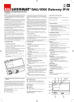
At the lower side of the casing the following connectors can be found (left to right):
At the upper side of the casing the following connectors can be found (left to right):
On the device front the following elements can be found:
PE L N
A1:
A2:
A3:
A4:
A5:
A6:
A7:
A8:
A9:
A10:
A11:
A12:
A13:
EIB bus connector
EIB Programming LED
EIB Programming Button
Mains Connector
DALI-connector
Connector passive binary input 1
Connector passive binary input 2
Display 2x12 chars for DALI
Commissioning
SCROLL-button
Prg/Set-button
ESC-button
Operating-LED (PWR)
Failure-LED (ERR)
The signage of the connectors on the casing is to be followed at all times!
Installation Notices and Warnings
• Life Hazard through Electrical Shock
• The device must only be installed and commissioned by qualified Electricians!
• The current country specific safety and accident prevention rules and regulations as well as the EIB guidelines must be respected at all
times!
• The device is destined for fixed mounting in dry interior locations!
• When connecting the mains wires, the mains power must be switched off.
• The device must not be opened. Defectuous devices must be returned to the manufacturer.
Merten GmbH & Co. KG
3/10