1
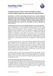
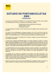
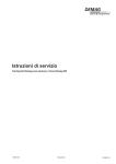
5.7.4 Transverse and longitudinal lateral stiffeners/V-type stiffeners 43207744.eps Fig. 19 Lateral stiffeners Fig. 20 V-type stiffener A) Stiffener, parallel or perpendicular B) V-type suspension fitting, parallel or perpendicular x no spring clip Tab. 17 Construction of lateral stiffeners as in Fig. 19, Page 36. The threaded rods must be subjected to tensile stress only and they must, therefore, be arranged in pairs. In order to avoid pressure forces and deformation, lateral stiffener arrangements must only be provided on the outside of crane runways. V-type suspension fittings may also be used to replace missing suspension points in vertical suspension arrange‐ ments. In such cases, the V-type suspension fittings must be arranged symmetrically to the vertical suspensions. Select an opening angle between 30° and 90°. Fit the V-type upper suspension bracket ((46), dimensions as for B-type upper suspension bracket) to the super‐ structure in the same way as vertical suspensions. The pin axis of the V-type upper suspension bracket must always: ● be horizontal, ● be parallel to the pin axis of the V-type hinged suspension bracket and ● perpendicular to the suspension rod axis. 36 211 259 44/110414 The V-type upper suspension bracket is only designed for connecting one suspension rod. If two or more connec‐ tions are fitted, a corresponding number of V-type upper suspension brackets must be fitted next to each other.