1
Operating instructions EUROTRONIK-20
Page: 11
Service terminal (only for service personnel)
ON
An osf service terminal (art. no. 3010000900) can be connected to
this controller for optimum adjustment of the controller to the
different types of swimming pool and to facilitate commissioning
and fault diagnosis. The connector for this is mounted on the circuit
board inside the device. The power supply to the controller
must be switched off before opening the housing and
plugging in the service terminal! Plugging the service
connector in or out when the device is on can destroy the
device! The operating time meter appears in the display of the
service terminal after switching on the controller, e.g.:
connector for service terminal
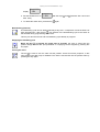
Further pages can be called up with the keys
changed after pressing the key .
Operating hours:
total:
238
switched on 156
Filt.-pump
26
and
. If necessary, the values in the top line can be
Operating cycles of the backwash controller
The following counter statuses are shown:
Backwash
Number of completely carried-out backwash cycles.
Empty
Number of emptying cycles.
Close
Number of closing cycles.
Input signals
The current input signals of the EUROTRONIK are shown in this line:
Pressure switch:
Switch status of a pressure switch connected to terminals 10 and 11.
B. fortnightly:
Switch position of the left DIP switch (backwash fortnightly).
B. interval:
Switch position of the right DIP switch (intermittent backwashing).
Microswitch
The current status of the microswitch in the bottom part of the housing, which is used by the controller to
detect whether the valve disk has been lowered, is shown on this page.
Light scanners
The measured values of the light scanners, which are used by the controller to detect the valve positions,
are shown on this page. Two values are shown for each of the five light scanners. The value in brackets
should be between 30 and 70. The other value should be more than 700 when the housing is open and
should fall notably on approaching a reflecting object.
The following lines enable the service technician to check the output relays of the controller.
Heater
This line shows whether the relay K3 is on. This relay is used to activate the heater while the filter pump is
on.
The following displays are possible:
Heater: OFF
The relay contact between terminals 3 and 5 (K3) is open, the heater is
disabled.
Heater: On
The relay contact between terminals 3 and 5 (K3) is closed, operation of the
heater is enabled.
When the heater is shown in the top line of the service terminal, it can be switched on or off: