1
Operating instructions EUROTRONIK-20
Page: 3
Mounting
The controller must be mounted in accordance with its system of protection so that it is protected against
moisture. The ambient temperature should lie between 0° C and + 40° C and should be as constant as
possible. The relative humidity should not exceed 95% and no condensation should occur. Direct incidence
of heat or sunlight on the device must be avoided.
The power supply to the device must be connected via an all-polar main switch with a contact gap width of
at least 3mm. The device must be switched off before the housing is opened.
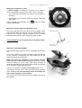
Shorter osf-pin
Preparation of the 6-way valve
Guide groove
Before mounting the EUROTRONIK it must be ensured that the
valve moves easily and is free of dirt.
The 6-way valve must be in the position Filter when mounting
the controller. In this position the handle of the valve must be
removed by driving the fastening pin out of the valve shaft. Then
insert the shorter osf pin delivered with the device in the middle of
the hole in the valve shaft. If the pin is too loose in the hole, it can
be fastened with a little adhesive or grease to facilitate mounting of
the controller. For later operation of the system it is immaterial
whether the pin is loose because it is centred by the housing of the
controller.
Preparation of the controller
The controller must be in the position Filter (position on delivery).
To equalise height differences of the valve shafts, it is necessary in the case of some valves to stick one or
more of the self-adhesive spacer disks delivered with the device under the housing of the controller.
Proceed as follows to determine whether one or more spacer disks are needed:
Move the 6-way valve into the position Filter.
Mount the EUROTRONIK-10 on the valve without spacer disk.
See "Mounting of the EUROTRONIK".
Push the feeler gauge delivered with the device between the
EUROTRONIK and valve.
If the feeler gauge fits between the EUROTRONIK and valve
exactly, the gap is optimal.
If the EUROTRONIK wobbles on the valve, one or more spacer
disks must be stuck under the EUROTRONIK (see sketch below).
Thereafter the EUROTRONIK must be mounted again and the test
with the feeler gauge repeated.
After mounting the feeler gauge has to be removed. The resultant
play has no negative influence on the operation of the system.
Insert
feeler
gauge