1
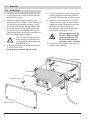
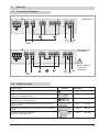
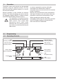
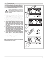
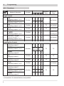
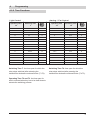
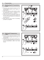
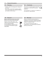
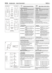
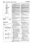
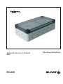
Universal-Receiver 2-Channel
IP66
RCU08
Operating Instructions
1
Introduction
1.1
Table of Contents
1
1.1
1.2
1.3
1.4
1.5
1.6
2
2.1
2.2
2.3
2.4
3
4
4.1
4.2
4.2.1
4.2.2
4.3
4.4
5
5.1
5.2
5.3
5.4
1.2
Page
Introduction
2
Table of Contents
2
Model
2
Technical Details
2
Intended Use
2
Safety Advice
2
Function
2
Start-Up
3
Selecting the Location
3
Mounting
4
Connection Diagram
5
Table of Loads
5
Operation
6
Programming
6
Operation Controls
6
Selecting the Operation Mode/Time 7
Function and Memorizing
Transmission Codes
Functions
8
Time Functions
9
Deleting Specific Transmission
10
Codes
Deleting All Transmission Codes
10
(Reset)
General Information
11
Cleaning
11
Disposal
11
Conformity
11
Warranty
11
Model
RCU08-5002E-01
1.3
1.4
868,3 MHz
Technical Details
868,3 MHz
230 V AC
2 relay outputs floating
(normally open and
two way contact)
Max. contact duty:
see Table of Loads
Degree of Protection:
IP66
Operating Temperature: -20 °C to +60 °C
Dimensions:
180 x 94 x 66 mm
Weight:
510 g
Scope of Delivery
Universal-Receiver RCU08, Cable Fittings M16,
Mounting Accessories, Operating Instructions
1.5
Intended Use
The unit may only be used as a radio control in
connection with mains consumers!
The manufacturer shall not be liable for any
damage caused by improper or non intended
use!
1.6
Safety Advice
Carefully read these operating
instructions before connecting and
operating this unit!
The device may only be installed and started
up by a qualified electrician!
All consumers may only be connected while
the unit is completely voltage free.
During programming the device
is under voltage! Programming
may only be performed with the
protective cover installed.
Have faulty units checked by the manufacturer!
Do not make any unauthorized alterations or
modifications to the unit!
Read the advices of the manufacturers about
the consumers you wish to operate!
Observe the requirements of EN 60669!
Frequency:
Power Supply:
Output:
2
Function
The Universal-Receiver RCU08 provides two relay outputs. These can be used to control either
two lamps or one motor for e.g. awnings/shutters or garage doors.
The Receiver is protected against splash water.
It can be operated wirelessly or manually using
two buttons.
32 transmission codes can be memorized and
for each transmission code an operating mode
as well as a specific time function for the operating time and switching time can be defined.
The following operating modes can be selected:
ON/OFF (2-button-control): for switching ON
use transmitter button A or C, for switching OFF
use transmitter button B or D.
ON (1-button-control): the consumer can be
switched ON with any separately learnt
transmitter button. An operating time of either
1.5 or 3 s can be selected.
OFF (1-button-control): the consumer can be
switched OFF with any separately learnt
transmitter button. An operating time of either
1.5 or 3 s can be selected.
Timer (1-button-control): the relay can be
switched with any transmitter button according
to the desired switching time T.
ON/OFF (1-button-control): using the toggle
function the consumer can be switched ON or
OFF by repeatedly pressing the transmitter
button.
UP/STOP/DOWN (2-button-control): use
transmitter button A or C to open awnings, the
buttons for the opposite direction B or D can be
used to drive the motor in the opposite direction
or stop the awning.
UP (1-button-control): use any transmitter button
to open the awning.
DOWN (1-button-control): use any transmitter
button to close the awning.
2
Start-Up
2.1
Selecting the Location
Choosing the location for the installation please
take into account that the reception quality and
sensitivity of the Universal Receiver RCU08 can
be disturbed by several factors:
equipment and systems without interference
suppression
other transmitters within the frequency range
atmospheric conditions and other factors.
Transmitter and receiver should be located in a
way that the shortest distance between them (air
line distance) is not or only slightly disturbed by
brick walls or other absorbing materials or any
disturbance. This way losses due to absorption
which influence the operation range of the
receiver can be reduced to a minimum.
Following values can be taken for reference:
Material
air/no obstacle
wood, hard plaster
brick/concrete
reinforced concrete
metal walls, metal gratings
Range
100%
80–95%
60–90%
10–50%
0–10%
Do not mount the receiver or the aerials on the
back of metal surfaces on the floor or in recesses
to avoid radio shadows.
When mounting the unit on metal surfaces, a
minimal distance of 10 cm should be kept.
Changes such as lengthening, shortening,
bending etc. may influence the receiving
properties considerably.
In case any problems occur contact you retailer
or for more information see: „www.eldat.de“
STOP (1-button-control): use any transmitter
button to stop the awning.
UP/STOP/DOWN (4-button control): use
transmitter button A to open awnings, button C
or D to stop it. Button B closes the awning.
3
2
Start-Up
2.2
Mounting
1. Screw off the housing cover of the unit. Lift
out the electronic components and remove
the protective cover.
2. Mount the cable fittings provided on the
housing and fix the bottom of the housing on
the wall using the screws provided. Close
the screw indentations with the sealing cap.
3. Insert the cables for the power supply and
the consumers to be switched through the
cable fittings and connect them according to
the connection diagram (page 5).
The unit may only be connected
to one phase. The contact may
not be used for safety extra-low
voltage (SELV)!
4. If needed connect the external pulse button
to (EXT1 and EXT2).
Only floating contacts may be used!
5. Fix the circuit board to the bottom of the
housing with the screws and washers
provided and mount the protective cover.
6. Switch on the power supply. The LED
„Power Supply“ lights up continuously.
7. Select the desired operation mode and
time function and memorize the
transmission code of the transmitter in
the receiver. (See page 7, 4.2).
During programming the
device is under voltage!
Programming may only
be performed with the
protective cover installed.
10. Screw the housing cover back onto the
bottom of the housing.
Housing Bottom
Sealing Cap
Circuit Board
select
1
µ 1
select
2
prog.
L 10A
230V ~
2
µ 2'
time
mode
Protective Cover
L 10A
L
Housing Cover
4
50Hz
2
Start-Up
2.3
Connection Diagram
Light Control
Awning Control/
Fan Control
Bridge between
X4 and X5
necessary!
2.4
Table of Loads
Type of Load
Motors 230 V, 50 Hz
Symbol
Max. Duty
4,0 A /
920 VA
10,0 A /
2.300 VA
2,6 A /
600 VA
10,0 A /
2.300 VA
Parallel-compensated fluorescent lamps with ferro-magnetic
loads
2,6 A /
600 VA
Capacity EB: electronic ballasts,
electronic transformers etc.
4,0 A /
920 VA
Resistive load:
bulbs, 230 V halogen lamp etc.
Inductive load: halogen lamps with wound transformers
(transformer at least 85% loaded)
Non- or serial-compensated fluorescent lamps with ferromagnetic loads
5
3
Operation
To perform a test run the device can be operated
manually using the selection buttons. For this
press and hold the selection button (>1.6 s) until
the device is switched.
Manual operation is also possible via external
buttons. The external buttons can not be used for
the operation modes ON/OFF (2-button-control)
and UP/STOPP/DOWN (4-button-control).
The switching via external buttons
has preference over the switching by
radio control. This means that
operations which have been
switched with the external buttons
can not be overruled by switching via
radio control.
4
Programming
4.1
Operating Controls
In order to operate the receiver with radio
transmitters the transmission code of a
transmitter has to be memorized for the desired
mode of operation.
Because one transmission code is allocated to
each pair of buttons, only one button has to be
pressed to memorize the transmission code.
While operating the device with radio
transmitters and during the memorizing process
the LED-Display flashes to indicate that the
radio connection is estabished.
LED
Switching Output 1
Selection Button
Switching Output 2
Selection Button
Switching Output 1
LED-Anzeige
Switching Output 2
Rotary Switch
Mode of Operation
µ 1
2
µ 2'
time
mode
230V ~ 50Hz
select 2
select 1
Rotary Switch
Time Function
LED
Reception Activity
prog.
Programming
button
6
L 10A
L 10A
L
LED
Power Supply
4
Programming
4.2
Selecting the Operation Mode/
Time Function and Memorizing
Transmission Codes
select 2
select 1
µ 1
µ 2'
2
time
mode
230V ~ 50Hz
prog.
L 10A
1. Briefly press the „prog.“ button. The acknowledgment signal can be heard in short intervals
and the LED for switching output 1 lights up.
2. With the „select“ button the switching output
(relay) can be chosen for which the transmission code is supposed to be memorized.
3. Set the desired operating mode with the rotary
switch „mode“ (see table „Functions“). Select
the desired operating and switching times with
the rotary switch „time“ (see table „Time
Functions“).
4. Press the button of the transmitter with which
the selected settings are supposed to be
switched and hold it until the long acknowledgment signal ceases. The transmission code
has now been memorized by the receiver
5. As soon as you can hear the acknowledgment
signal again in short intervals additional
transmission codes can be memorized or the
memorizing procedure can be aborted by
briefly pressing the „prog.“ button.
L
L 10A
mode
230V ~ 50Hz
select 2
select 1
µ 1
2
µ 2'
time
During programming the device is
under voltage! Programming may only
be performed with the protective cover
installed!
prog.
L 10A
L
L 10A
Note: All programming processes can be aborted
by pressing the „prog.“ button.
2
µ 2'
time
mode
230V ~ 50Hz
select 2
select 1
µ 1
prog.
L 10A
L 10A
L
7
4
Programming
mode
4.2.1 Functions
Mode of Operation
Light Control
ON
switching output 1 or 2
1*)
OFF
switching output 1 or 2
2
ON
switching output 1 or 2
3
4
5
Control
Transmitter Button Operation
A
B
C
D
Time
Switching
Time
x
x
2-button
not limited
x
x
1-button
x
x
x
x
T2
not limited
OFF
switching output 1 or 2
1-button
x
x
x
x
T2
not limited
TIMER
switching output 1 or 2
1-button
x
x
x
x
operation time
+
switching time
1-button
x
x
x
x
not limited
O N / O F F To g g e l
( O N O F F O N O F F. . . )
switching output 1 or 2
Awning-/Fan Control
6
UP
switching output 1
STOP
switching output 1 or 2
x
2-button
opposite opposite
direction direction
DOWN
switching output 2
x
T3
T4
x
7
UP
switching output 1
1-button
x
x
x
x
T3
T4
8
DOWN
switching output 2
1-button
x
x
x
x
T3
T4
9
STOP
switching output 1 or 2
1-button
x
x
x
x
x
x
A *)
UP
switching output 1
STOP
switching output 1 or 2
DOWN
switching output 2
not limited
x
4-button
*) Connection of external buttons not possible.
8
x
x
T3
T4
4
Programming
4.2.2 Time Functions
Switching Time
T
Operating Time
T3
Switching Time
T4
time
Operating Time
T2
Awning - / Fan Control
time
Light Control
0
0
0
0
unlimited
0
1.5 s
0.5 s
1
0
150 s
1
3 s
2 s
2
0
90 s
2
0
4 s
3
0
30 s
3
0
6 s
4
0
15 s
4
0
10 s
5
0
0.4 s
5
0
20 s
6
1.5 s
unlimited
6
0
30 s
7
1.5 s
150 s
7
8
0
1 min
8
1,5 s
90 s
0
3 min
9
1.5 s
30 s
9
0
5 min
A
1.5 s
15 s
A
0
7 min
B
3 s
unlimited
B
0
9 min
C
3 s
150 s
C
0
15 min
D
3 s
90 s
D
0
45 min
E
3 s
30 s
E
0
120 min
F
3 s
15 s
F
Switching Time T: the time span for which the
relay stays switched after releasing the
transmission button/the external button (T+T2).
Switching Time T4: time span for which the
relay stays switched after pressing the
transmission button/the external button (T4-T3).
Operating Time T2 and T3: the time span for
which a transmission key has to be held down to
actuate the switching process.
9
4
Programming
4.3
Deleting Specific Transmission
Codes
1. Press the „prog.“ button for at least 1.6 s. The
select 2
select 1
µ 1
µ 2'
2
time
230V ~ 50Hz
mode
acknowledgment signal can be heard in a
double rhythm.
2. Select the switching output (relay) for which
the transmission code is memorized with
selection button „select 1" or „select 2".
3. Press and hold the transmission button for
which the code is supposed to be deleted until
the acknowledgment signal can be heard and
the LED lights up.
4. Briefly press the „prog.“ button. The deleting
procedure is completed.
prog.
L 10A
L
L 10A
>1,6 s
mode
µ 2'
2
time
230V ~ 50Hz
select 2
select 1
µ 1
prog.
L 10A
Deleting All Transmission
Codes
230V ~ 50Hz
select 2
select 1
µ 1
µ 2'
2
time
1. Press the „prog.“ button for at least 1.6 s. The
acknowledgement signal can be heard in a
double rhythm.
2. Press the „prog.“ button again for at least 1.6 s.
A long acknowledgement signal can be heard
and all transmission codes have been
deleted.
mode
4.4
L
L 10A
prog.
L 10A
L
L 10A
>1,6 s
µ 1
2
µ 2'
time
mode
230V ~ 50Hz
select 2
select 1
prog.
L 10A
>1,6 s
10
L 10A
L
5
General Information
5.1
Cleaning
Carefully wipe the housing with a damp lint
free cloth.
Do not use solvent-based cleaning agents.
These can damage your health and destroy
the surface of the housing.
5.2
Disposal
Waste electrical products may not be
disposed of with household waste!
Dispose of the waste product via a
collection point for electronic scrap or
via your specialist dealer.
Put the packaging material into the
recycling bins for cardboard, paper
and plastics.
5.3
Conformity
This product complies with the essential
requirements of the R&TTE-Directive
1999/5EG.
The declaration of conformity is available on
the internet at: www.eldat.de
5.4
Warranty
Within the statutory warranty period we
undertake to rectify free of charge by repair or
replacement any product defects arising from
material or production faults.
Any unauthorized tampering with, or
modifications to, the product shall render this
warranty null and void.
11
Customer Service
If, despite correct handling, faults or
malfunctions occur or if the product was
damaged, please contact the company at the
address below:
ELDAT GmbH
Im Gewerbepark 14
D-15711 Zeesen
Deutschland
Telefon:
+49 (0) 3375-9037-310
Fax:
+49 (0) 3375-9037-90
E-Mail:
[email protected]
Internet:
www.eldat.de
86161 0908 GB