1
• The manual must also be available to third parties for all work performed on the system.
• This manual is a component of the charge controller and must be included with it
when sold on.
1.4.Exclusion of liability
The manufacturer cannot monitor the compliance to this manual as well as the conditions and methods during the installation, operation, usage and maintenance of the
charge controller. Improper installation of the system may result in damage to property
and, as a result, to bodily injury. Therefore, we assume no responsibility and liability for
loss, damage or costs which result or are in any way related to incorrect installation,
improper operation and incorrect use and maintenance. Similarly, we assume no
responsibility for patent right or other right infringements of third parties caused by
usage of this charge controller. The manufacturer reserves the right to make changes to
the product, technical data or assembly and operating instructions without prior notice.
2. Charge controller with fuzzy logic
2.1.Overall function of the charge controller in the PV system
The charge controller is used in PV power supplies with battery bank for the hobby and
leisure, residential, business, commercial and small company areas. The charge controller monitors the charge status of the battery, controls the charging process and the
connection/disconnection of the loads. This allows the battery use to be optimised and
its service life to be significantly extended. The charge controller is set for lead batteries
with liquid electrolyte on delivery and can be switched to a setting for batteries with solid electrolyte. The charge controller can be used for all solar modules to the maximum
connection value of the module short circuit current.
2.2.Monitoring and control functions
• SOC calculation
Using a special new algorithm, the controller can „learn“ the characteristic curve of the
battery. After this learning phase, the SOC charge status of the battery is indicated with
an average precision of approx. 90 %. This charge status is the basis for most control
and monitoring functions.
• Overcharge protection
Frequent overcharging damages the battery bank. The charging process and the overcharge protection are therefore controlled by a new hybrid actuator with pulse-width
modulation to guarantee gentle charging of the battery.
• Voltage recognition
A special measurement process renders battery sensor lines. The voltage drop on the
battery line is compensated out after the first full charge.
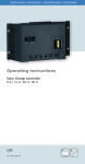
LED 1 (Info) for operating status and fault
messages
LED 2 (Battery) for charge status,
load shedding and early warning
Plug-in fuse:
8 A controller: 10 A
12 A controller:15 A
20 A controller: 20 A
Integrated temperature sensor
Connection terminals
30 A controller: 30 A
Figure 1