1
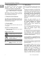
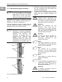
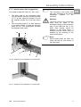
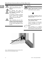
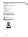
7856.003
7856.005
7856.006
7856.008
7856.010
7856.015
7856.016
7856.020
7856.043
7856.321
7856.323
Power System
Module - PSM
Assembly and operating instructions
We reserve all rights for this technical documentation. Without our previous consent it must neither be reproduced nor made available
for third parties. Nor must it be put to any other misuse by the receiver or third parties. Any violation of the above obliges the violating
party to pay compensation and may lead to penal action.
Microsoft Windows is a registered trademark of Microsoft Corporation.
Acrobat Reader is a registered trademark of Adobe Systems Incorporated.
EN
Table of Contents
1.
Documentation Notes................................4
11. Mounting of the Lockout ......................... 28
12. Maintenance ........................................... 29
RETENTION OF THE DOCUMENTS ................. 4
USED SYMBOLS.......................................... 4
13. Cleaning ................................................. 29
2.
Safety Notes .............................................4
15. Accessories for PSM Bus bars ............... 30
3.
Introduction ...............................................5
4.
Service and Service Address ....................5
15.1. 7856.003, 7856.005, 7856.006, 7856.008,
7856.010, 7856.020, 7856.016, 7856.043,
7856.321 AND 7856.323..................................... 30
15.2. 7856.015 ............................................... 30
15.3. 7856.003, 7856.005, 7856.006, 7856.008,
7856.010, 7856.015, 7856.016, 7856.020,
7856.043, 7856.321 AND 7856.323.................... 30
15.4. 7856.010, 7856.016, 7856.020, 7856.008
31
1.1.
1.2.
5.
PSM Power System Module .....................6
5.1.
5.2.
5.3.
5.4.
5.5.
5.6.
6.
PSM with fixed infeed..............................10
6.1.
6.2.
6.3.
6.4.
7.
9.
SCOPE OF SUPPLY ................................... 10
FEATURES ............................................... 10
CONFIGURATION ...................................... 10
OPTIONAL ACCESSORIES .......................... 11
16.1.
32
16.2.
TECHNICAL SPECIFICATIONS – PSM BUS BAR
SCOPE OF SUPPLY ................................... 12
FEATURES ............................................... 12
CONFIGURATION ...................................... 12
OPTIONAL ACCESSORIES .......................... 13
WIRING DIAGRAM ..................................... 14
Metered PSM ..........................................15
17. Assembly Instructions............................. 38
8.1.
SCOPE OF SUPPLY ................................... 15
8.2.
FEATURES ............................................... 15
8.3.
CONFIGURATION ...................................... 15
8.4.
OPTIONAL ACCESSORIES .......................... 16
8.5.
DESCRIPTION........................................... 16
8.6.
CONFIGURATION OF THE METERED PSM .. 18
8.7.
CONNECTION TO THE CMC-TC ................ 19
8.7.1.
Associated documents .................. 19
8.7.2.
Commissioning .............................. 19
8.8.
WIRING DIAGRAM ..................................... 22
17.1. MOUNTING IN THE RITTAL FLEXRACK(I)..... 40
17.2. MOUNTING IN RITTAL TS ENCLOSURES ..... 41
17.2.1. Mounting in Rittal TS enclosures,
base and roof frames .................................... 42
17.2.2. Mounting in Rittal TS enclosures,
punched mounting sections .......................... 43
17.3. MOUNTING IN RITTAL TE ENCLOSURES ..... 43
17.4. MOUNTING THE PLUG-IN MODULES ............ 44
17.5. INFEED STRAIN RELIEF (SUGGESTION)....... 45
17.6. ALTERNATIVE POSSIBILITIES FOR MOUNTING
OF THE CABLE CLAMP BRACKET ............................ 46
17.7. ALTERNATIVE POSSIBILITIES FOR MOUNTING
OF THE CABLE CLAMP BRACKET ............................ 46
PSM Plus ................................................12
PSM Version 32 A, Single-Phase ...........23
9.1.
9.2.
9.3.
9.4.
9.5.
9.6.
SCOPE OF SUPPLY ................................... 23
FEATURES ............................................... 23
CONFIGURATION ...................................... 23
OPTIONAL ACCESSORIES .......................... 23
FUNCTION PRINCIPLE ............................... 24
WIRING DIAGRAM ..................................... 25
10. Power System Module with a 32 A Infeed
26
10.1.
10.2.
10.3.
10.4.
10.5.
2
16. Technical Specifications ......................... 32
TECHNICAL SPECIFICATIONS – PSM WITH
FIXED INFEED....................................................... 33
16.3. TECHNICAL SPECIFICATIONS – PSM PLUS
WITH 4-WAY INFEED ............................................. 34
16.4. TECHNICAL SPECIFICATIONS – PSM BUS BAR
WITH 3-PHASE CURRENT MEASUREMENT ............... 35
16.5. TECHNICAL SPECIFICATIONS – PSM 32 A,
SINGLE-PHASE ..................................................... 36
16.6. TECHNICAL SPECIFICATIONS – PSM 32 A, 3PHASE 37
7.1.
7.2.
7.3.
7.4.
7.5.
8.
SCOPE OF SUPPLY ..................................... 6
FEATURES ................................................. 6
CONFIGURATION ........................................ 6
OPTIONAL ACCESSORIES ............................ 7
FUNCTION PRINCIPLE ................................. 8
WIRING DIAGRAM ....................................... 9
14. Disposal.................................................. 29
18. Electrical Connection of the Bus bar ...... 47
18.1.
18.2.
18.3.
TECHNICAL DATA OF THE INFEEDS ............ 47
EARTHING ............................................... 48
INFEED CONNECTION PLUG, DATA AND
ASSIGNMENT ....................................................... 49
18.4. TERMINAL ASSIGNMENT............................ 49
SCOPE OF SUPPLY ................................... 26
FEATURES ............................................... 26
CONFIGURATION ...................................... 26
OPTIONAL ACCESSORIES .......................... 26
WIRING DIAGRAM ..................................... 27
PSM
Power System Module
empty page
EN
PSM
Power System Module
3
Documentation Notes
EN
1. Documentation Notes
2. Safety Notes
The audience for this guide is the technical
specialists familiar with the assembly,
installation and operation of the Rittal PSM.
• You should read this operating guide prior
to the commissioning and store the guide
so it is readily accessible for subsequent
use.
Rittal cannot accept any liability for damage
and operational malfunctions that result from
the non-observance of this guide.
Observe the subsequent general safety notes
for the installation and commissioning of the
unit:
-
Assembly and installation of the Rittal PSM,
in particular for wiring the enclosures with
mains power, may be performed only by a
trained electrician. Other tasks associated
with the Rittal PSM, such as the assembly
and installation of system components with
tested standard connectors, and the
operation and configuration of the Rittal
PSM may be performed only by instructed
personnel.
-
Observe the valid regulations for the
electrical installation for the country in
which the unit is installed and operated, and
the national regulations for accident
prevention. Also observe any companyinternal regulations (work, operating and
safety regulations).
-
Prior to working at the Rittal PSM system, it
must be disconnected from the power
supply and protected against being
switched on again.
-
An electrical test must be performed after
the completion of the assembly, installation
and maintenance work! All protective
conductor terminals and the voltages at all
connection plugs, and at each individual
module slot must be checked.
-
Use only genuine or recommended parts
and accessories (see Chapter 15). The use
of other parts can void the liability for any
resulting consequences.
-
Do not make any changes to the Rittal PSM
that are not described in this guide or in the
associated guides.
-
The operational safety of the unit is
guaranteed only for its approved use. The
limit values stated in the technical
specifications (see Chapter 16) may not be
exceeded under any circumstances. In
particular, this applies to the permitted
ambient temperature range and to the
permitted IP protection category. When
used with a higher required IP protection
category, the Rittal PSM must be installed
1.1. Retention of the documents
This guide and all associated documents are
part of the product. They must be given to the
operator of the unit and must be stored so they
are available when needed.
1.2. Used symbols
The following safety and other notes are used
in this guide:
Symbol for a handling instruction:
•
This bullet point indicates that you should
perform an action.
Safety and other notes:
Danger!
Immediate danger to life and limb!
Warning!
Possible danger for the product
and the environment!
Note!
Useful information
features.
4
and
special
PSM
Power System Module
Introduction
in a housing or enclosure with a higher IP
protection category.
-
-
-
Operation of the Rittal PSM system in direct
contact with water, aggressive media, or
inflammable gases and fumes is prohibited.
In addition to these general safety notes,
also observe any special safety notes listed
for the specific tasks in the individual
sections.
The strain relief for the connection cable
must be made in the immediate vicinity of
the connection plug of the PSM bus bar. If
the strain relief bracket cannot be attached
to the base frame, a suitable punched
section must be installed for the mounting
of the strain relief bracket.
various country-specific versions. Rittal does
not accept any warranty for any other uses of
PSM buses.
4. Service and Service Address
If you have any questions concerning technical
or other issues related to our product range,
Rittal will be pleased to provide any required
support.
You may contact us at the address indicated
below.
Rittal GmbH & Co. KG
Auf dem Stuetzelberg
D-35745 Herborn
Germany
E-mail: [email protected]
3. Introduction
Note!
The stable flow of information and production is
the 'lifeline' of an enterprise. Loss of data,
failure of function and production causes
extensive and in many cases life-threatening
damage. Therefore, it is the declared company
objective to ensure a maximum of safety and
reliability.
Rittal offers support to achieve this: By means
of universal competence in effective prevention,
comprehensive
safety,
and
centralised
organisation, i.e. teamwork for IT safety and
reliability! This result is an optimum
combination of power management and
administration, enclosure monitoring, server
administration and climate control components.
Please indicate always the item
number in the reference line.
Support Tel.:
Complaints:
Fax:
+49 (0) 2772/505-9052
+49 (0) 2772/505-1855
+49 (0) 2772/505-2319
Further information concerning the Rittal PSM
can be downloaded from the RimatriX5
homepage www.rimatrix5.com
The solution for the power management is the
Rittal PSM – Power System Module. This
concept includes complete power distribution of
the enclosure, i.e. power supply, distribution
and protection.
The PSM offers a revolutionary energy
management for IT racks. The modular power
supply system permits the power supply using
a vertical bus bar on which the power system
modules are simply clipped.
The system is made complete by its
sophisticated modular structure. A basic
installation can be implemented in next to no
time. When demands then grow over time, the
original system can simply be expanded with
further plug-in modules, also available in
PSM
Power System Module
5
EN
PSM Power System Module
EN
5. PSM Power System Module
Model No.: DK 7856.010
Model No.: DK 7856.020
Model No.: DK 7856.008 (for 2200mm Racks)
VDE Reg. No. A592
Tested and certified in accordance
DIN EN 60950 (VDE 0850):2000-12.
with
Danger!
An electrical test must be
performed after the completion
of the assembly, installation and
maintenance work!
All
protective
conductor
terminals and the voltages at all
connection plugs, and at each
individual module slot must be
checked.
5.1. Scope of supply
1 x bus bar
2 x female multipoint connection strip
1 x operating instructions
1 x cable bracket, incl. assembly parts
5.2. Features
-
Shock-hazard-protected design, i.e. it is not
necessary to configure the whole bus bar at
once
-
Modular design for simple installation
-
Optimised cable management
-
Complete compatibility with Rittal enclosure
systems
5.3. Configuration
The vertical bus bar is an H-shaped aluminium
section. The power distribution for the individual
plug-in modules is realised in the rear,
concealed section. The bus bar can be clipped
directly into the vertical enclosure frame
members of Rittal flexRack(i), or else retrofitted
to other existing racks. To upgrade TS
enclosures you require the DK 7856.022 or DK
7856.023 mounting kit and for TE enclosures
the DK 7000.684 PSM adaptor.
Once the bus bar is fitted in the enclosure, a
voltage supply must be provided in a suitable
form. This can be done either by way of a
three-phase connector, e.g. IEC309 16 A, or
with permanent wiring to the plug-in terminal
strips provided on the bus bars. Connecting
lines are available as Rittal accessories.
The principal features of the Rittal PSM are:
Warning!
-
Two separate 3~ infeeds,
redundant configurations
-
96 A current in total, i.e. 48 A per infeed
-
Four
plug-in
modules
can
be
accommodated on a 1200 mm bus bar,
which corresponds to 24 IEC 320-C13
appliance sockets
The strain relief for the connection
cable must be made in the
immediate vicinity of the connection
plug of the PSM bus bar. If the
strain relief bracket cannot be
attached to the base frame, a
suitable punched section must be
installed for the mounting of the
strain relief bracket.
-
Seven
plug-in
modules
can
be
accommodated on a 2000 mm bus bar,
which corresponds to 42 IEC 320-C13
appliance sockets
-
-
6
permitting
Eight
plug-in
modules
can
be
accommodated on a 2200mm bis bar,
which corresponds to 48 IEC 320-C13
appliance sockets
Various country modules, UK, USA, F/B,
earthing-pin plug, IEC 320-C13/C19
appliance sockets
Note!
Observe the correct fuse values!!
Refer to the notes on the rating
plate.
The plug-in modules can now be clipped onto
the bus bar in the desired positions. The
modules are locked into place using the lugs on
the end faces. A module can only be released
from the bus bar after it has been unlocked.
PSM
Power System Module
PSM Power System Module
To unlock a module, the lugs on the end faces
must be pressed down at the same time at both
ends. The module can then be pulled off the
bus bar.
EN
The connection direction of the modules is
used to select infeed I or II
Condition: All infeeds must be connected by the
customer.
For information about assembly and connection
of the bus bar please see Chapters 17 and 18.
All important operating parameters, such as
application limit temperature and humidity,
allowed voltage supply, back-up fuses, etc., are
described in more detail in Chapter 16.1
5.4. Optional accessories
Note!
Article numbers, see Chapter 15.
-
3~ over voltage protection
-
Various country-specific plug-in modules
-
DK 7856.025 or DK 7856.026 connection
cable
PSM
Power System Module
7
PSM Power System Module
EN
5.5. Function principle
The diagram shows circuit A and circuit B of a
2000 mm strip.
Fig. 1: Function principle
The red arrow on the PSM module points up
The black arrow on the PSM module points up
B infeed
A infeed
For single-phase 32 A infeed, the B circuit must
be protected using a 16 A class C circuit
breaker.
For single-phase 32 A infeed, the A circuit must
be protected using a 16 A class C circuit
breaker.
8
PSM
Power System Module
PSM Power System Module
5.6. Wiring diagram
EN
The diagram shows infeed I and infeed II of a
2000 mm and a 1200 mm strip
M odul 7
Modul4
M odul 6
Modul3
M odul 5
Modul2
M odul 4
Modul1
M odul 3
L1 L2 L3 N PE
M odul 2
PE N L3 L2 L1
C ircuit 1
C ircuit 2
Power System Module
400V
Note!
L1 L2 L3 N PE
PSM
Circuit2
400V
Fig. 3: Wiring diagram
Rittal PSM 1200 mm
M odul 1
400V
Fig. 2: Wiring diagram
Rittal PSM 2000 mm
PE N L3 L2 L1
Circuit1
The wiring of the 2200mm Model
has the same plan, with one extra
Slot for a PSM Module.
400V
9
PSM with fixed infeed
EN
6. PSM with fixed infeed
Model No.: DK 7856.005 (with one infeed)
Model No.: DK 7856.006 (with two infeeds)
VDE Reg. No. A592
Tested and certified in accordance
DIN EN 60950 (VDE 0850):2000-12.
with
Danger!
An electrical test must be
performed after the completion
of the assembly, installation and
maintenance work!
All
protective
conductor
terminals and the voltages at all
connection plugs, and at each
individual module slot must be
checked.
6.1. Scope of supply
1 x bus bar with fixed infeeds
1 x operating instructions
1 x assembly parts
-
Shock-hazard-protected design, i.e. it is not
necessary to configure the whole bus bar at
once
-
Modular design for simple installation
-
Optimised cable management
-
Complete compatibility with Rittal enclosure
systems
6.3. Configuration
The vertical bus bar is an H-shaped aluminium
section. The power distribution for the individual
plug-in modules is realised in the rear,
concealed section. The bus bar can be clipped
directly into the vertical enclosure frame
members of Rittal flexRack(i), or else retrofitted
to other existing racks. To upgrade TS
enclosures you require the DK 7856.022 or DK
7856.023 mounting kit and for TE enclosures
the DK 7000.684 PSM adaptor.
The models 7856.005 and 7856.006 did have a
fixed connection from the power cable to the
bus bar, so it is no more possible to disconnect
the plug on the bar and there is no need for a
cable bracket.
6.2. Features
The principal features of the Rittal PSM are:
-
Two separate 3~ infeeds,
redundant configurations
permitting
Note!
Model DK 7856.005 only got ONE
3~ infeed
-
96 A current in total, i.e. 48 A per infeed
The strain relief for the connection
cable must be made in the
immediate vicinity of the connection
plug of the PSM bus bar. If the
strain relief bracket cannot be
attached to the base frame, a
suitable punched section must be
installed for the mounting of the
strain relief bracket.
Note!
Note!
Model DK 7856.005: 48A current in
total
Observe the correct fuse values!!
Refer to the notes on the rating
plate.
-
Seven
plug-in
modules
can
be
accommodated on a 2000 mm bus bar,
which corresponds to 42 IEC 320-C13
appliance sockets
-
Various country modules, UK, USA, F/B,
earthing-pin plug, IEC 320-C13/C19
appliance sockets
10
Warning!
PSM
Power System Module
PSM with fixed infeed
The plug-in modules can now be clipped onto
the bus bar in the desired positions. The
modules are locked into place using the lugs on
the end faces. A module can only be released
from the bus bar after it has been unlocked.
EN
To unlock a module, the lugs on the end faces
must be pressed down at the same time at both
ends. The module can then be pulled off the
bus bar.
The connection direction of the modules is
used to select infeed I or II (redundancy, see
Section 5.5).
Condition: All infeeds must be connected by the
customer.
Note!
Model DK 7856.005 only got one
infeed. So it does not matter in
which direction you put in the
modules
For information about assembly and connection
of the bus bar please see Chapters 17 and 18.
All important operating parameters, such as
application limit temperature and humidity,
allowed voltage supply, back-up fuses, etc., are
described in more detail in Chapter 16.2.
6.4. Optional accessories
Note!
Article numbers, see Chapter 15.
-
3~ over voltage protection
-
Various country-specific plug-in modules
PSM
Power System Module
11
PSM Plus
EN
7. PSM Plus
Power System Module with 4
Infeeds
Model No.: DK 7856.015
Designed in accordance with DIN EN 609501 (VDE 0805):2003-03.
Danger!
An electrical test must be
performed after the completion
of the assembly, installation and
maintenance work!
All
protective
conductor
terminals and the voltages at all
connection plugs, and at each
individual module slot must be
checked.
7.1. Scope of supply
1 x bus bar
1 x operating instructions
1 x cable bracket, incl. assembly parts
7.2. Features
The principal features of the Rittal PSM Plus
are:
-
Four separate 3~ infeeds, permitting
redundant configurations
-
192 A current available, 48 A per infeed
-
Six
plug-in
modules
can
be
accommodated on a 2000 mm bus bar,
which corresponds to 36 IEC 320-C13
appliance sockets
-
IEC 60320 C13, IEC 60320 C19 plug-in
modules, and earthing-pin plug
-
Shock-hazard-protected design, i.e. it is
not necessary to configure the whole bus
bar at once
-
Modular design for simple installation
-
Optimised cable management
-
Full compatibility with Rittal enclosure
systems
12
7.3. Configuration
The vertical bus bar is an H-shaped aluminium
section. The power distribution for the individual
plug-in modules is realised in the rear, concealed
section. The bus bar can be clipped directly into
the vertical enclosure frame members of Rittal
flexRack(i), or else retrofitted to other existing
racks. To upgrade TS enclosures you require the
DK 7856.022 or DK 7856.023 mounting kit and
for TE enclosures the DK 7000.684 PSM adaptor.
Once the bus bar is fitted in the enclosure, a
voltage supply must be provided in a suitable
form. This can be done either by way of a threephase connector, e.g. IEC309 16 A, or with
permanent wiring. Connecting lines are available
as Rittal accessories.
Note!
Observe the correct fuse values!!
Refer to the notes on the rating
plate.
The plug-in modules can now be clipped onto the
bus bar in the desired positions. They are locked
into place by way of the lugs on the end faces. A
module can only be released from the bus bar
after it has been unlocked.
To unlock a module, the lugs on the end faces
must be pressed down at the same time at both
ends. The module can then be pulled off the bus
bar.
Condition for the redundancy: All infeeds must be
connected by the customer (see Section 7.5).
For information about assembly and connection
of the bus bar please see Chapters 17 and 18.
All important operating parameters, such as
application limit temperature and humidity,
allowed voltage supply, back-up fuses, etc., are
described in more detail in Chapter 16.3
PSM
Power System Module
PSM Plus
7.4. Optional accessories
EN
Note!
Article numbers, see Chapter 15.
-
DK 7856.018 connection cable
-
3~ over voltage protection
-
IEC 60320 C13, IEC 60320 C19 plug-in
modules, and earthing-pin plug
PSM
Power System Module
13
PSM Plus
EN
7.5. Wiring diagram
Modul 6
Modul 5
Modul 4
Modul 3
Modul 2
Modul 1
L1 L2 L3 N PE
L1 L2 L3 N PE
L1 L2 L3 N PE
L1 L2 L3 N PE
Circuit 1
Circuit 3
Circuit 4
Circuit 2
400V
400V
400V
400V
Fig. 5: PSM Plus wiring diagram
14
PSM
Power System Module
Metered PSM
Note!
8. Metered PSM
Power System Module with
measuring function
Model No.: DK 7856.016 (2 infeeds, 16A)
Model No.: DK 7856.003 (1 infeed, 32A)
-
Six plug-in modules can be inserted on a 2metre bus bar; this corresponds to 36 IEC
320 appliance sockets
-
Shock-hazard-protected design, i.e. it is not
necessary to configure the whole bus bar at
once
-
IEC 60320 C13, IEC 60320 C19 plug-in
modules, and earthing-pin plug
-
Modular design for simple installation
-
Optimised cable management
-
Full compatibility
systems
-
Connection to the CMC-TC
-
Measurement and display on the current,
voltage, power, work (energy), frequency
display
Designed in accordance with DIN EN 60950-1
(VDE 0805):2003-03.
Danger!
An electrical test must be
performed after the completion of
the assembly, installation and
maintenance work!
All protective conductor terminals
and the voltages at all connection
plugs, and at each individual
module slot must be checked.
Warning!
To prevent damage to the Rittal
Metered PSM, ensure that "N"
and "L" for the infeed are not
interchanged.
Note!
A power pack is required if the
Metered PSM is not connected to
the CMC-TC Processing Unit.
Model number for the required
power pack: DK7201.210, a
connection cable is also required,
see Chapter 15.
8.1. Scope of supply
1 x bus bar
1 x operating instructions
1 x cable bracket, incl. assembly parts
2 x female multipoint connection strip
(7856.016)
1 x Connection cable wit CE-Plug, 32A
(7856.003)
8.2. Features
The principal features of Rittal Metered PSM
are:
-
Two separate 3~ infeeds,
redundant configurations
-
96 A current available, 48 A per infeed
PSM
Power System Module
EN
The Model DK 7856.003 has just
one singlephase Infeed and
offers max. 32A.
permitting
with
Rittal
enclosure
8.3. Configuration
The vertical bus bar is an H-shaped aluminium
section. The power distribution for the individual
plug-in modules is realised in the rear,
concealed section. The bus bar can be clipped
directly into the vertical enclosure frame
members of Rittal flexRack(i), or else retrofitted
to other existing racks. To upgrade TS
enclosures you require the DK 7856.022 or DK
7856.023 mounting kit and for TE enclosures
the DK 7000.684 PSM adaptor.
Once the bus bar is fitted in the enclosure, a
voltage supply must be provided in a suitable
form. This can be done either by way of a
three-phase connector, e.g. IEC309 16 A, or
with permanent wiring. Connecting lines are
available as Rittal accessories.
Note!
Observe the correct fuse values!
Refer to the notes on the rating
plate.
15
Metered PSM
Warning!
EN
The strain relief for the connection
cable must be made in the
immediate vicinity of the connection
plug of the PSM bus bar. If the
strain relief bracket cannot be
attached to the base frame, a
suitable punched section must be
installed for the mounting of the
strain relief bracket.
The plug-in modules can now be clipped onto
the bus bar in the desired positions. They are
locked into place by way of the lugs on the end
faces. A module can only be released from the
bus bar after it has been unlocked.
8.5. Description
The Power System Module Metered PSM
offers revolutionary power management for IT
racks. The modular power supply system
realises power input via a vertical mounting rail
(bus bar) with a three-phase infeed. The
individual Power System Modules are simply
clipped to this rail.
The Metered PSM bus bar provides the
possibility to measure the voltage, current,
power and energy per infeed and per phase.
The mains frequency can also be measured
per infeed. The Metered PSM bus bar also
provides the possibility to set the upper and
lower threshold values for voltage and current
for each phase.
To unlock a module, the lugs on the end faces
must be pressed down at the same time at both
ends. The module can then be pulled off the
bus bar.
Condition for the redundancy: All infeeds must
be connected by the customer.
For information about assembly and connection
of the bus bar please see Chapters 17 and 18.
All important operating parameters, such as
application limit temperature and humidity,
allowed voltage supply, back-up fuses, etc., are
described in more detail in Chapter 16.4.
8.4. Optional accessories
Note!
Article numbers, see Chapter 15.
-
DK 7856.025 or DK 7856.026 connection
cable
-
3~ over voltage protection
-
Various plug-in modules
-
Connection to the CMC-TC
16
I/O port: connection
Jog Dial
on the CMC-TC or
power pack
LCD display
Fig.6: Metered PSM
The Jog Dial is used to configure the Metered
PSM bus bar and to navigate through the
display menu represented in the LCD display.
The connection to the CMC-TC allows all
parameters of the bus bar to be queried using a
Web interface. The inclusion in a network
management system using SNMP is also
possible.
If the Metered PSM bus bar is operated directly
with a power pack, all values can be read from
the display. The power pack is connected to the
I/O port. A remote configuration and
administration is not possible for operation with
power pack for the Metered PSM bus bar.
PSM
Power System Module
Metered PSM
If the threshold value of the Metered PSM bus
bar is undershot or overshot, the display
flashes and the error message will be displayed
at the lower edge.
Infeed 1
EN
Infeed 2
Fig.7: Metered PSM
The angled plug connectors permit a parallel
routing of the connection cable to the Metered
PSM bus bar.
Note!
The Model DK 7856.003 has a
fixed infeed with DIN-Bolting and
a 32A CE-Plug..
PSM
Power System Module
17
Metered PSM
EN
8.6. Configuration of the Metered PSM
Start display
Select
infeed
by
turning and confirm
by pressing
Infeed 1
Infeed 2
Select parameters
by
turning
and
confirm by pressing
Only the measured
values are displayed
for the "Total" display
Total
Phase 1
Phase 2
Phase 3
Exit
Total
Energy (kWh)
Power (kW)
Frequency (Hz)
Select parameters
by turning and
confirm by
pressing
Use "Exit" to
return to start
display
Exit
Phase 1/2/3
Energy (kWh)
Power (kW)
Voltage (V)
Current (A)
Set "high" and "low"
setpoint for voltage or
current by turning and
confirm by pressing. Use
"Exit" to leave the menu
item.
Display all
parameters
Use "Exit" to return
to start display
Exit
Configuration of the display
Press Jog Dial for more
than 3 sec., then
release to reach the
configuration menu.
Turn Jog Dial to
change the value and
confirm by pressing.
Use "Exit" to leave the
menu item.
Circuit 1
Circuit 2
Circuit 1+2
Brightness
Inverse
Rotate
Exit
Use "Exit" to
return to start
display
Sequence diagram 1: Configuration of the Metered PSM
18
PSM
Power System Module
Metered PSM
EN
8.7. Connection to the CMC-TC
8.7.1.
Associated documents
The guide for the CMC-TC Processing Unit II
(DK 7320.100) and its safety notes also apply
together with this guide.
You can download the German version of the
guide from:
http://www.rimatrix5.de/service_support/downlo
ads.asp
"Power" must be specified as product group.
Here you find software updates for the metered
PSM as well.
To view the guide you require the Acrobat
Reader program; Acrobat Reader can be
downloaded from www.adobe.com
8.7.2.
Commissioning
The Metered PSM bus bar can be managed
completely using the CMC-TC PU. The
Metered PSM bus bar is connected directly with
the sensor unit input of the PU. The bus bar is
recognised automatically and immediately
operational after confirmation of the changed
configuration on the PU.
The name of the Metered
PSM bus bar is also used
to send SNMP traps.
Notification text
Upper and lower threshold
value
Alarm management, see
CMC-TC PU manual
Fig.8: Tab 1
PSM
Power System Module
19
Metered PSM
EN
Tabs 1 to 12 are constructed identically. Tabs 1
to 3 represent the L1, L2 and L3 voltages of
infeed 1. Tabs 4 to 6 represent the current of
infeed 1. Tabs 7 to 12 provide the values for
infeed 2.
Tab 13 provides the values for the power and
the energy of infeed 1. Tab 14 provides this
information for infeed 2.
Fig.9: Tab 13
20
PSM
Power System Module
Metered PSM
Tab 15 provides an overview for the voltage
and current values of both infeeds and all
phases.
EN
Fig.10: Tab 15
PSM
Power System Module
21
Metered PSM
EN
8.8. Wiring diagram
7856.016:
7856.003:
Modul 6
Modul5
Messm odul
Modul 4
Modul 3
Modul 2
Modul 1
L1 L2 L3 N PE
PE N L3 L2 L1
Circuit 1
Circuit 2
400V
400V
Fig. 11: Metered PSM wiring diagram
22
PSM
Power System Module
PSM Version 32 A, Single-Phase
9. PSM Version 32 A, SinglePhase
Model No.: DK 7856.321
Model No.: DK 7856.043 (with integrated RCD)
-
Integrated fuses
-
Modular design for simple installation
-
Optimised cable management
-
Complete compatibility with Rittal enclosure
systems
Danger!
An electrical test must be
performed after the completion
of the assembly, installation and
maintenance work!
All
protective
conductor
terminals and the voltages at all
connection plugs, and at each
individual module slot must be
checked.
9.3. Configuration
The vertical bus bar is an H-shaped aluminium
section. The power distribution for the individual
plug-in modules is realised in the rear,
concealed section. The bus bar can be clipped
directly into the vertical enclosure frame
members of Rittal flexRack(i), or else retrofitted
to other existing racks. To upgrade TS
enclosures you require the DK 7856.022 or DK
7856.023 mounting kit and for TE enclosures
the DK 7000.684 PSM adaptor.
9.1. Scope of supply
Note!
1 x bus bar with CEKON connection cable and
connection plug
1 x operating instructions
1 x cable bracket, incl. assembly parts
9.2. Features
The principal features of the Rittal PSM are:
-
A 1~ infeed with connection cable and CEE
connection plug
-
32 A current are available
-
Integrated protection using a 16 A, class C
circuit-breaker
-
The Model 7856.043 has two integrated
RCDs (Residual Current protectiv Devices)
and allows the application in areas as
described in DIN VDE 0100-410.
EN
Observe the correct fuse values!
Refer to the notes on the rating
plate.
The plug-in modules can now be clipped onto
the bus bar in the desired positions. They are
locked into place by way of the lugs on the end
faces. A module can only be released from the
bus bar after it has been unlocked.
To unlock a module, the lugs on the end faces
must be pressed down at the same time at both
ends. The module can then be pulled off the
bus bar.
The connection direction of the modules is
used to select circuit/fusing A/F1 or
circuit/fusing B/F2
For information about assembly and connection
of the bus bar please see Chapters 17 and 18.
-
Six plug-in modules can be inserted on a 2metre bus bar; this corresponds to 36 IEC
60320 appliance sockets
All important operating parameters, such as
application limit temperature and humidity,
allowed voltage supply, back-up fuses, etc., are
described in more detail in Chapter 16.5
-
Shock-hazard-protected design, i.e. it is not
necessary to configure the whole bus bar at
once
9.4. Optional accessories
-
Various country modules, UK, USA, F/B,
earthing-pin plug, IEC 320-C13/C19
appliance sockets
PSM
Power System Module
Note!
Article numbers, see Chapter 15.
-
Over voltage protection
-
Various country-specific plug-in modules
23
PSM Version 32 A, Single-Phase
EN
9.5. Function principle
The diagram shows circuit A and circuit B of a
2000 mm strip.
Fig. 12: Function principle
24
The red arrow on the PSM module
points up
The black arrow on the PSM module
points up
F1 fuse
F2 fuse
For single-phase 32 A infeed, the B
circuit (F1 fuse) is tapped after the
16 A class C circuit breaker.
For single-phase 32 A infeed, the A
circuit (F2 fuse) is tapped after the
16 A class C circuit breaker.
PSM
Power System Module
PSM Version 32 A, Single-Phase
9.6. Wiring diagram
EN
Fig. 13: PSM 32 A (single-phase)
Note!
The
Model
7856.043
has
additionally to the two fuses two
integrated RCDs.
PSM
Power System Module
25
Power System Module with a 32 A Infeed
EN
10. Power System Module with a
32 A Infeed
Model No.: DK 7856.323
VDE Reg. No. A592
Tested and certified in accordance
DIN EN 60950 (VDE 0805):2000-12.
with
Danger!
An electrical test must be
performed after the completion
of the assembly, installation and
maintenance work!
All
protective
conductor
terminals and the voltages at all
connection plugs, and at each
individual module slot must be
checked.
10.3. Configuration
The vertical bus bar is an H-shaped aluminium
section. The power distribution for the individual
plug-in modules is realised in the rear,
concealed section. The bus bar can be clipped
directly into the vertical enclosure frame
members of Rittal flexRack(i), or else retrofitted
to other existing racks. To upgrade TS
enclosures you require the DK 7856.022 or DK
7856.023 mounting kit and for TE enclosures
the DK 7000.684 PSM adaptor.
Once the bus bar is fitted in the enclosure, a
voltage supply must be provided in a suitable
form. The six slots for the modules are each
assigned their own fuse. See Section 10.5.
Note!
Observe the correct fuse values!
Refer to the notes on the rating
plate.
10.1. Scope of supply
1 x bus bar with connection cable
2 x female multipoint connection strip
1 x operating instructions
1 x cable bracket, incl. assembly parts
10.2. Features
The principal features of the Rittal PSM are:
The plug-in modules can now be clipped onto
the bus bar in the desired positions. They are
locked into place by way of the lugs on the end
faces. A module can only be released from the
bus bar after it has been unlocked.
To unlock a module, the lugs on the end faces
must be pressed down at the same time at both
ends. The module can then be pulled off the
bus bar.
-
One 3~ infeed
-
96 A current available, 32 A per phase
-
Six plug-in modules can be accommodated
on a 2000 mm bus bar, which corresponds
to 36 IEC 320 appliance sockets
All important operating parameters, such as
application limit temperature and humidity,
allowed voltage supply, back-up fuses, etc., are
described in more detail in Chapter 16.6
-
Various country modules, UK, USA, F/B,
earthing-pin plug, IEC 320-C13 appliance
sockets
10.4. Optional accessories
-
For information about assembly and connection
of the bus bar please see Chapters 17 and 18.
Note!
Shock-hazard-protected design, i.e. it is not
necessary to configure the whole bus bar at
once
-
3~ over voltage protection
-
Modular design for simple installation
-
Various country-specific plug-in modules
-
Optimised cable management
-
Complete compatibility with Rittal enclosure
systems
26
Article numbers, see Chapter 15.
PSM
Power System Module
Power System Module with a 32 A Infeed
10.5. Wiring diagram
EN
Fig. 14: PSM 32 A (3-phase) wiring diagram
PSM
Power System Module
27
Mounting of the Lockout
EN
11. Mounting of the Lockout
for DK7856.321 and DK 7856.323
The DK 7856.321 and DK 7856.323 PSM bus
bars provide a possibility to prevent the
unintentional activation of the circuit breakers
by the installation of the supplied lockout.
Note!
The installation of the lockout does
not affect the actual operation of
the line circuit breaker.
Fig. 18: Correct installation of the lockout
Opening for lock or
chain.
Fig. 15: Lockout
Press
Press
Fig. 19: Installation examples
Fig. 16: 1. Installation steps
The removal of the lockout can be
prevented by raising the plastic cap and
inserting a lock or a chain.
The lockout must be
inserted in these
openings.
Fig. 17: Openings for the installation of the lockout
28
PSM
Power System Module
Maintenance
12. Maintenance
EN
The Rittal PSM is a maintenance-free system
that does not need to be opened for the
purposes of installation or operation. Opening
the housing or any accessory components will
void any warranty and liability claims.
13. Cleaning
The Rittal PSM system can be cleaned using a
dry cloth. The use of aggressive substances
like cleanser's solvent, acids, etc. will destroy
the system.
14. Disposal
Because
the
Rittal
PSM
comprises
predominantly of aluminium and plastic
materials, it should be sent for proper disposal
and recycling when it is no longer needed. The
infeed cables should be removed before
disposal.
PSM
Power System Module
29
Accessories for PSM Bus bars
EN
15. Accessories for PSM Bus bars
Note!
The
accessories
are
sorted
according to the use with PSM bus
bars.
DK 7856.203
DK 7856.204
DK 7856.220
DK 7856.230
15.1. 7856.003, 7856.005, 7856.006,
7856.008, 7856.010, 7856.020,
7856.016, 7856.043, 7856.321 and
7856.323
DK 7856.240
Active PSM 6-way, 4x
with earthing-pin plug
Active PSM 6-way, with
4x C19
IEC320 Power System
Module individually fused
IEC 320 C19 PSM plugin module
PSM plug-in module,
earthing-pin plug, red
DK 7856.170 Over voltage protection
Optional power pack for
DK 7856.016 with:
Designation
PSM 6-way IEC320 plugDK 7856.070 in module with fuse
DK 7201.210
PSM 6-way IEC320 plugDK 7856.080 in module without fuse
DK 7200.211 GB connection cable
Model No.:
DK 7856.082 IEC320 C13 6-way red
PSM 4-way earthing-pin
DK 7856.090 plug-in module with fuse
PSM 4-way earthing-pin
DK 7856.100 plug-in module without
fuse
PSM 4-way French plugDK 7856.110 in module with fuse
PSM 4-way French plugDK 7856.120 in module without fuse
DK 7200.210 D/F/B connection cable
DK 7200.213 CH connection cable
15.2. 7856.015
Model No.:
Designation
6-way C13 module with
DK 7856.081
2x16 A inputs
2-way earthing-pin plug
DK 7856.101 module with 2x16 A
inputs
4-way C19 module with
DK 7856.231
2x16 A inputs
DK 7856.170 Over voltage protection
PSM 4-way USA plug-in
DK 7856.130 module with fuse
PSM 4-way USA plug-in
DK 7856.140 module without fuse
PSM 4-way UK plug-in
DK 7856.150 module with fuse
PSM 4-way UK plug-in
DK 7856.160 module without fuse
PSM 4-way CH plug-in
DK 7856.180 module with fuse
PSM 4-way CH plug-in
DK 7856.190 module without fuse
DK 7856.201 Active PSM 8-way
individually switchable
30
3-phase mains
DK 7856.018 connection cable,
EN 60 309
DK 7856.017 Extension cable
15.3. 7856.003, 7856.005, 7856.006,
7856.008, 7856.010, 7856.015,
7856.016, 7856.020, 7856.043,
7856.321 and 7856.323
Model No.:
Designation
DK 7856.210 PSM light module
DK 7000.684 PSM adaptor for TE rack
DK 7856.022
TS mounting kit for static
installation
DK 7856.023 TS mounting kit, mobile
PSM
Power System Module
Accessories for PSM Bus bars
15.4. 7856.010, 7856.016, 7856.020,
7856.008
EN
Model No.:
Designation
Connection cable, 3DK 7856.025 phase CEKON 5-pole /
16 A
Connection cable, 1DK 7856.026 phase CEKON 3-pole /
16 A
Connection cable, UPS,
DK 7856.027
1-phase C14/X-Com
PSM
Power System Module
31
Technical Specifications
EN
16. Technical Specifications
16.1. Technical specifications – PSM bus bar
Model No. DK 7856.010, 1200 mm enclosure height
Model No. DK 7856.020, 2000 mm enclosure height
Model No. DK 7856.008, for 2200mm Racks
Bus bar
Height
Width
Depth
Weight
Potential
equalisation
Earthing
IP protection
category
Temperature
range
Humidity range
Storage
temperature range
Power
connection:
Aluminium, anodised
For 1200 mm and 2000 mm enclosure height
approx. 60 mm
approx. 55 mm
approx. 1.5 kg without packing, without modules
Yes
Yes, separate housing earthing point (6.3 mm flat-pin
connector), min. 2.5 mm² cross-section
IP 20 to EN 60529
+5° C to 45° C
+41° F to 113° F
5% to 95% relative humidity, non-condensing
-20° C to 60° C
-4° F to 140° F
Power supply
Infeed I: 3~400 VAC + N + PE, max. current 3 x 16 A
Infeed II: 3~400 VAC + N + PE, max. current 3 x 16 A
Fusing
Back-up fuse, installed by the customer, 16 A per phase.
Observe the data on the bus bar rating plate!
Max. cable length
50 m, observe the cable cross-section and backup
fuse!
Tension spring terminal, plug-type
Number of poles
Max. cross-section [mm²]
Max. cross-section [AWG]
Connection plug of EN rated voltage
the infeed
Rated peak voltage
Level of contamination
Rated current
Bared length [mm]
Bared length [inch]
32
5
4
12
500 V
6 kV
3
16 A
8
0.33
PSM
Power System Module
Technical Specifications
EN
16.2. Technical specifications – PSM with fixed infeed
Model No.: DK 7856.005, 2000 mm enclosure height with one infeed
Model No.: DK 7856.006, 2000 mm enclosure height with two infeeds
Bus bar
Height
Width
Depth
Weight
Potential
equalisation
Earthing
IP protection
category
Temperature
range
Humidity range
Storage
temperature range
Power
connection:
Aluminium, anodised
For enclosure height 2000 mm
approx. 60 mm
approx. 55 mm
approx. 5 kg without packing, without modules
Yes
Yes, separate housing earthing point (6.3 mm flat-pin
connector), min. 2.5 mm² cross-section
IP 20 to EN 60529
+5° C to 45° C
+41° F to 104° F
5% to 95% relative humidity, non-condensing
-20° C to 60° C
-4° F to 140° F
Power supply
Infeed I: 3~ 400 VAC + N + PE, max. current 3 x 16 A
Infeed II: 3~ 400 VAC + N + PE, max. current 3 x 16A
Fusing
Back-up fuse, installed by the customer, 16 A per phase.
Observe the data on the bus bar rating plate!
Max. cable length
50 m, observe the cable cross-section and backup
fuse!
3-phase circuit with neutral conductor and PE
separate neutral conductor
Connection plug of
common PE
the infeed
max. current 3x16 A per infeed
PSM
Power System Module
33
Technical Specifications
EN
16.3. Technical specifications – PSM Plus with 4-way infeed
Model No. DK 7856.015
Bus bar
Height
Width
Depth
Weight
Potential
equalisation
Earthing
IP protection
category
Temperature
range
Humidity range
Storage
temperature range
Power
connection:
Aluminium, anodised
For enclosure height 2000 mm
approx. 60 mm
approx. 55 mm
approx. 5 kg without packing, without modules
Yes
Yes, separate housing earthing point (6.3 mm flat-pin connector),
min. 2.5 mm² cross-section
IP 20 to EN 60529
+5° C to 40° C
+41° F to 104° F
5% to 95% relative humidity, non-condensing
-20° C to 60° C
-4° F to 140° F
Power supply
Circuit I: 3~ 400 VAC / 230 VAC + N + PE, max. current 3 x 16 A
Circuit II: 3~400 VAC / 230 VAC + N + PE, max. current 3 x 16 A
Circuit IIII: 3~ 400 VAC / 230 VAC + N + PE, max. current 3 x 16 A
Circuit IV: 3~ 400 VAC / 230 VAC + N + PE, max. current 3 x 16 A
Fusing
Back-up fuse, installed by the customer, 16 A per phase. Observe
the data on the bus bar rating plate!
Max. cable length
50 m, observe the cable cross-section and backup fuse!
4x Wieland GST 18 connection plug
3-phase circuit with neutral conductor and PE
Connection plug of
separate neutral conductor
the infeed
common PE
max. current 3x16 A per infeed
34
PSM
Power System Module
Technical Specifications
EN
16.4. Technical specifications – PSM bus bar with 3-phase current measurement
Model No. DK 7856.016
Model No. DK 7856.003
Bus bar
Height
Width
Depth
Weight
Potential
equalisation
Earthing
IP protection
category
Temperature
range
Humidity range
Storage
temperature range
Power
connection:
Aluminium, anodised
for enclosure height 2000 mm
approx. 60 mm
approx. 55 mm
approx. 5 kg without packing, without modules
Yes
Yes, separate housing earthing point (6.3 mm flat-pin connector),
min. 2.5 mm² cross-section
IP 20 to EN 60529
+5° C to 40° C
+41° F to 104° F
5% to 95% relative humidity, non-condensing
-20° C to 60° C
-4° F to 140° F
Power supply
7856.016:
Circuit I: 400 VAC / N + PE,
max. current 3 x 16 A
Circuit II: 400 VAC / N + PE,
max. current 3 x 16A
Fusing
Back-up fuse, installed by the customer, 16 A per phase
(7856.016), respectively 32 A (7856.003). Observe the data on
the bus bar rating plate!
Max. cable length
50 m, observe the cable cross-section and backup fuse!
7856.003:
Circuit I: 230V 50Hz/60Hz
7856.016:
Tension spring terminal, plugtype
Number of poles
Max. cross-section [mm²]
Connection plug of Max. cross-section [AWG]
the infeed
EN rated voltage
Rated peak voltage
Level of contamination
Rated current
Bared length [mm]
Bared length [inch]
PSM
Power System Module
7856.003:
CE-Connection-plug, 32 A
5
4
12
500 V
6 kV
3
16 A
8
0.33
35
Technical Specifications
EN
16.5. Technical specifications – PSM 32 A, single-phase
Model No. DK 7856.321
Model No. DK 7856.043
Bus bar
Height
Width
Depth
Weight
Potential
equalisation
Earthing
IP protection
category
Temperature
range
Humidity range
Storage
temperature range
Power
connection:
Aluminium, anodised
For 1200 mm and 2000 mm enclosure height
approx. 60 mm
approx. 55 mm
approx. 3.5 kg without packing, without modules
Yes
Yes, separate housing earthing point (6.3 mm flat-pin
connector), min. 2.5 mm² cross-section
IP 20 to EN 60529
+5° C to 45° C
+41° F to 113° F
5% to 95% relative humidity, non-condensing
-20° C to 60° C
-4° F to 140° F
Power supply
Power supply: 1~ 200-230 VAC + N + PE, max. current 1 x 32A
Integrated fusing
16 A circuit-breaker, characteristic C
7856.043 offers additionally two RCDs (residual current: 30mA)
Fusing installed by Back-up fuse, installed by the customer, 32 A per phase.
the customer
Observe the data on the bus bar rating plate!
Max. cable length
Connection plug of
the infeed
36
50 m, observe the cable cross-section and backup fuse!
32 A blue CEKON 32 A plug, single-phase
Cable cross-section: 3G6mm2
PSM
Power System Module
Technical Specifications
16.6. Technical specifications – PSM 32 A, 3-phase
EN
Model No. DK 7856.323
Bus bar
Height
Width
Depth
Weight
Potential
equalisation
Earthing
IP protection
category
Temperature
range
Humidity range
Storage
temperature range
Power
connection:
Aluminium, anodised
For 1200 mm and 2000 mm enclosure height
approx. 60 mm
approx. 55 mm
approx. 4 kg without packing, without modules
Yes
Yes, separate housing earthing point (6.3 mm flat-pin
connector), min. 2.5 mm² cross-section
IP 20 to EN 60529
+5° C to 45° C
+41° F to 113° F
5% to 95% relative humidity, non-condensing
-20° C to 60° C
-4° F to 140° F
Power supply
Power supply: 3~ 400 VAC + N + PE, max. current 3 x 32 A
Fusing
Back-up fuse, installed by the customer, 32 A per phase.
Observe the data on the bus bar rating plate!
Max. cable length
50 m, observe the cable cross-section and backup
fuse!
Connection plug of
the infeed
PSM
3x32 A variant with red CEKON 32 A plug, 3-phase
Cable Cross-section: 5G6mm2
Power System Module
37
Assembly Instructions
EN
17. Assembly Instructions
Warning!
The Rittal PSM system must be installed in an
enclosure or case system, which also provides
protection against external influences. The
length of lines should not exceed the lengths
specified in the technical data for preventing
losses caused by unnecessary line lengths.
It is imperative to disconnect any
device operated via the plug-in
modules of Rittal PSM from the
power supply, e.g. by pulling the
mains connection cable, before
commencing any maintenance or
repair work.
In addition, the allowed ambient temperature
and humidity ranges must be complied with,
just as the IP protection category as required
for the specific application. The corresponding
details are contained in Chapter 16.
Compliance with a higher required IP protection
category can be achieved by installation into an
enclosure having the required protection
category.
General notes to be observed when installing
the PSM:
Warning!
When
using
accessories
in
connection with the Rittal PSM, the
installation
and
operating
instructions for the accessories and
for the Rittal PSM must be
observed.
Note!
The Rittal PSM can either be
clipped into the vertical enclosure
frame members of the Rittal
flexRack(i), or else retrofitted to
other
enclosures
using
the
corresponding Rittal mounting kit.
Note!
During installation the existing
national and regional regulations of
the country, in which the Rittal PSM
is to be installed and operated,
must be observed.
Electrical shock danger!
No objects must be inserted into
the socket receptacles of the plugin modules, nor into the connectors
on the bus bar, as high electrical
voltages may be present and may
even result in the death of the
persons involved.
38
Warning!
In the case of plug-in modules with
built-in circuit breakers, it must be
ensured that the module concerned
is disconnected from the power
supply before resetting the circuit
breaker. This is achieved, for
example, by pulling the mains
connection cable.
Electrical shock danger!
Existing safety devices must not be
made ineffective.
Electrical shock danger!
The Rittal PSM may only be
operated with a PE connection.
The PE connection is made at the
terminal strip. The prerequisite here
is that the connecting cable is
connected with a PE terminal on
the mains side.
Warning!
The voltage of the electrical
connection must correspond to the
nominal values specified on the
rating plate and in Chapter 16.
Electrical shock danger!
Before commencing any work on
the Rittal PSM, it must always be
disconnected from the power
supply and secured to prevent
inadvertent reconnection.
Warning!
The Rittal PSM must not be
modified in any way. The internal
wiring and connections made by
the manufacturer must not be
altered!
PSM
Power System Module
Assembly Instructions
Note!
Warning!
Cables are gathered and secured
by fitting the enclosed cable
brackets in the case or enclosure.
Note!
See Chapter 18.
Warning!
The strain relief for the connection
cable must be made in the
immediate vicinity of the connection
plug of the PSM bus bar. If the
strain relief bracket cannot be
attached to the base frame, a
suitable punched section must be
installed for the mounting of the
strain relief bracket.
The DK 7856.022/023 mounting kit
is required to assemble the TS
enclosure. The two mounting
brackets are screwed to the end
covers of the PSM. The two
fastening holes in the brackets
permit mounting at various depths.
It must be ensured, however, that
the
PSM
remains
readily
accessible for installed punched
section.
Mounting in flexRack(i), also see 17.1.
Mounting in TS enclosures, also see 17.2.
Mounting in TE enclosures, also see 17.3.
Note!
In the case of enclosures with a
swing frame, mounting is only
possible on the side of the
enclosure where the swing frame
hinges are fitted. Otherwise, the
swing radius of the swing frame will
be impaired.
Note!
In 600 mm wide enclosures, the
rear 482.6 mm (19”) level may be
slightly obstructed by the PSM bus
bar. This must be taken into
account when assembling the
enclosure.
PSM
Power System Module
39
EN
Assembly Instructions
EN
17.1. Mounting in the Rittal flexRack(i)
A
B
•
With Rittal flexRack(i), the Rittal PSM can
be clipped into the vertical frame members
of the enclosure.
•
To this end, the bus bar (A) is placed up
against the side of the vertical section (B).
Ensure that the bus bar sits in the side
groove over the whole length. The two parts
are then clipped together by pressing the
other side of the bus bar to overcome the
resistance of the mounting lugs.
This requires a certain amount of force.
Warning!
Fig.20: flexRack(i)
Once the two parts are locked
together, they cannot be separated
again without causing damage to
one or both parts.
Note!
The 24 U bus bar
installed in the 42
The length of the
cause it to shift
section.
should not be
U enclosures.
bus bar can
in the frame
Note!
View of the snapped-in bus bar
with vertical enclosure frame.
Fig. 21: flexRack(i) with installed PMS bus bar
40
PSM
Power System Module
Assembly Instructions
17.2. Mounting in Rittal TS enclosures
C
EN
•
The two mounting brackets (B) from the
mounting kit must be used. These brackets
are screwed to the plastic end covers of the
bus bar with the enclosed screws (C).
Note!
B
The depth at which the bus bar is
mounted in the enclosure can be
varied by screwing the mounting
brackets to the plastic covers the
other way round.
Fig. 22: Installation start
B
Fig. 23: PSM bus bar with mounting bracket
PSM
Power System Module
41
Assembly Instructions
EN
17.2.1. Mounting in Rittal TS enclosures,
base and roof frames
D
B
A
C
•
For retrofitting, the Rittal PSM can also be
fastened to the base and roof frames (D).
The two mounting brackets (B) from the
mounting kit must be used.
The 90°-angled brackets (B) are fastened to
the end covers at the top and bottom of the
bus bar. The bus bar (A) with the mounted
brackets is then fastened to the appropriate
roof and base frame elements using the
enclosed screws and washers (C).
Fig. 24: Installation in the TS 8 enclosure
Fig. 25: Installed PSM bus bar in the TS 8 enclosure
42
PSM
Power System Module
Assembly Instructions
17.2.2. Mounting in Rittal TS enclosures,
punched mounting sections
EN
Note!
If the punched mounting sections
are used, the bus bars can also be
fitted in enclosures of different
heights. It is also possible to realise
a combination of punched section
and roof or base frame mounting.
Warning!
The strain relief for the connection
cable must be made in the
immediate vicinity of the connection
plug of the PSM bus bar. If the
strain relief bracket cannot be
attached to the base frame, a
suitable punched section must be
installed for the mounting of the
strain relief bracket.
Fig. 27: Installation on punched mounting section
To accommodate varying heights of enclosure
or Rittal PSM, another mounting variant is
possible:
To do this, the punched mounting section must
be fitted in the enclosure at the height of the
bus bar end covers.
When doing so, observe the assembly
instructions of the enclosure type concerned.
Here, too, the mounting brackets are fastened
to the two end covers of the bus bar.
The bus bar can then be mounted on the
punched sections.
17.3. Mounting in Rittal TE enclosures
The PSM adaptor DK7000.684 is required for
installation in the Rittal TE enclosure.
Note!
The associated assembly manual
accompanies the PSM adaptor DK
7000.684.
Fig. 26: Installation on punched mounting section
PSM
Power System Module
43
Assembly Instructions
EN
•
17.4. Mounting the plug-in modules
•
Note!
It is only possible to use original
Rittal plug-in modules with Rittal
PSM. The use of any other parts
will render all warranty claims void.
Depending on the type, a maximum of seven
modules or four modules can be inserted in a
2000 mm or 1200 mm, respectively.
It is not necessary to mount always the full
possible number of modules, as the bus bar is
designed with shock-hazard protection.
Note!
Important: to ensure a redundant
configuration for DK 7856.010, DK
7856.020, DK 7856.015, DK
7856.016, all infeeds must be
connected. For 7856.321, the
backup fusing and the load
distribution must be taken into
consideration. See Chapter 18, and
Sections 5.6, 7.5, 8.8, 9.6, 10.5.
C
A
The plug-in module (C) is placed centred on
the two connectors (B) and locked into
place with a gentle push.
If a plug-in module needs to be removed,
release all four retaining lugs (D) at the
same time and carefully withdraw the
module.
Warning!
Caution: when consumers are
connected to a module, the power
to all these consumers will be lost if
the plug-in module is unlocked.
Warning!
When the modules (C) are
mounted, there must be no
consumers in the power sockets.
First, mount the modules on the
bus bar, and then connect the
corresponding consumers.
Warning!
To remove a plug-in module (C),
you should first remove all
consumers connected to the
module concerned.
Note!
The plug-in modules (C) can also
be mounted and removed while the
bus bar (A) is in operation.
Note!
The module (C) is mounted
correctly, if all four retaining lugs
(D) at the end faces have locked
into the bus bar.
B
Note!
Fig. 28: Mounting the plug-in modules
When doing so, ensure that the
module is not tilted.
Note!
D
D
If the modules are equipped with a
miniature circuit breaker, it can be
reset after being activated by
pressing the yellow pin.
Warning!
A possible short-circuit must be
corrected beforehand.
Fig. 29: Installed plug-in module
44
PSM
Power System Module
Assembly Instructions
17.5. Infeed strain relief (suggestion)
Note!
(For model number DK 7856.010, .020, .016)
The mounting of the strain relief
may vary according to the specific
installation
situation
in
the
enclosure.
•
•
The strain relief for the connection cable
must be realised using the provided bracket
(C). To do this, attach the bracket (C) with
the supplied screws (D) to the base frame
(E).
The connecting cable (F) is then fastened
to the cable bracket (C) with the enclosed
cable ties (G). This configuration provides
for adequate strain relief.
B
A
Warning!
The strain relief for the connection
cable must be made in the
immediate vicinity of the connection
plug of the PSM bus bar. If the
strain relief bracket cannot be
attached to the base frame, a
suitable punched section must be
installed for the mounting of the
strain relief bracket.
Note!
Where gland plates are fitted, the
cable can also be tied directly to
the base frame.
F
E
C
D
G
Fig. 30: Example for the installation of a strain relief
Fig. 31: Example for the installation of a strain relief
PSM
Power System Module
45
EN
Assembly Instructions
EN
17.6. Alternative possibilities for
mounting of the cable clamp
bracket
Fig.35: Side view 2, from outside
Fig.32 4: Side view 1, inside from below
17.7. Alternative possibilities for
mounting of the cable clamp
bracket
For the PSM bus bars DK 7856.321 and DK
7856.323, the strain relief on the bus bar is
made using a PG screwed cable gland. It may
be necessary to use cable ties to attach the
infeed line(s) to a mounting bracket.
Fig. 33: Top view 1, outside from above
Fig.36: Side view 3, from outside
Fig. 34: Side view 2, from inside
46
PSM
Power System Module
Electrical Connection of the Bus bar
18. Electrical Connection of the
Bus bar
The 7856.010 and 7856.020 bus bars can be
used to provide a redundant power supply
system for IT enclosures. To achieve this, the
Rittal PSM has two separate infeed
possibilities: infeed I, infeed II (see Section
5.6). For both infeeds, the supplied accessories
contain the required connection plugs to attach
a fixed connection cable. As an alternative, you
can use a preassembled connection lead with
CEKON plug, see Chapter 15. This plug
connector is described in Section 18.4. It is
used to connect a permanently installed
connection cable to the bus bar.
Within the bus bar, the two three-phase circuits
are completely independent of each other, i.e.
they each make available L1, L2, L3, N and PE.
The protective conductors of the two circuits
are placed together in the bus bar and
connected to the bus bar housing.
18.1. Technical data of the infeeds
EN
Note!
Note that the product uses a multiinfeed bus bar, DK 7856.005 DK
7856.007, DK 7856.321 and DK
7856.323 are exceptions.
Warning!
If the bus bar is connected via the
CEKON/CEE connecting cable, the
corresponding CEKON/CEE supply
socket must be as close as
possible to the bus bar.
Warning!
If the bus bar is not connected via
a CEKON/CEE connector, but is
instead installed permanently, a
suitable
mains
power
disconnection device must be
provided.
Risk of death!
The Rittal PSM Plus provides four separate
infeed possibilities: infeed 1 to infeed 4 (see
Section 7.5).
The Rittal Metered PSM provides two separate
infeed possibilities: infeed 1 to infeed 2 (see
Section 8.8).
Rittal PSM Version 32 A, single-phase,
provides one infeed possibility. Each module
slot is protected with its own circuit-breaker
(see Section 9.6). Given the appropriate
selection of the backup fusing, load distribution
and group formation of loads, a redundancy
can be provided.
Rittal PSM Version 32 A, three-phase, provides
an infeed possibility separated into two circuits
using two circuit-breakers (see Section 9.6).
The modules do not need to be turned.
The bus bar and the plug-in
modules must not be opened.
Risk of death!
If, for some reason, work needs to
be performed on the bus bar, all
circuits must be disconnected from
the mains and protected against
being switched on again.
Risk of death!
A clear label must be provided at
the disconnecting device of both
power circuits, describing how the
equipment is to be properly
disconnected from the power
supply.
Warning!
The cable strain relief bracket
enclosed in the package should be
used at the infeed.
PSM
Power System Module
47
Electrical Connection of the Bus bar
Warning!
EN
Observe all warnings and rating
plates attached to the bus bar!
Danger!
An electrical test must be
performed after the completion of
the assembly, installation and
maintenance work!
All protective conductor terminals
and the voltages at all connection
plugs, and at each individual
module slot must be checked.
18.2. Earthing
Warning!
The bus bar possesses a housing
earthing point in the area of the
infeed marked with the symbol:
A conductive connection must be
made from this earthing point to the
enclosure frame.
Warning!
When connecting the bus bar,
ensure that an appropriate fuse is
provided. Observe the regulations
of the local power supply company,
as well as the rating plate on the
bus bar.
Sep. housing earthing point min.
cross-section 2.5 mm²
The PE conductor of both power
circuits is brought to a common
housing potential in the bus bar.
Note!
The connection of a separate
protective conductor is not required
for DK 7856.321 and DK 7856.323.
Fig. 37: Separate earthing point in the vicinity of the
infeed for bus bars with plug-in infeed
48
PSM
Power System Module
18.3. Infeed connection plug, data and
assignment
EN
1-conductor female multi-point conductor with
side-mounted locking, 5-pole for insertion in the
base terminal block.
The following conductors can be used:
Single-wire
Multi-wire
Fine-wire with tinned single cores
Max. cross-section 4 mm²
Max. cross-section 12 AWG
Bared length 8 mm
Bared length 0.33 inch
Compacted strands with wire end ferrule1) or
pin-type cable socket (crimped gas-tight).
Note!
1)
When wire end ferrules are used,
the next-smaller cross-section must
be chosen.
Danger!
The connection plug does not
serve as an on-load isolator!
18.4. Terminal assignment
1
2
3 4
5
PE N L1 L2 L3
Fig. 38: Terminal assignment
PSM
Power System Module
49
EN
empty page
50
PSM
Power System Module
01/11 – A38653 11 IT74
Rittal GmbH & Co. KG · Postfach 1662 · D-35726 Herborn
Telefon +49(0)2772 505-0 · Telefax +49(0)2772 505-2319 · eMail: [email protected] · www.rittal.de