1
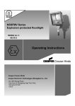
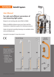
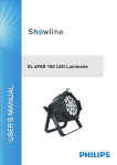
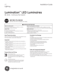
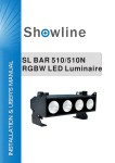
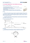
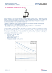
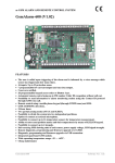
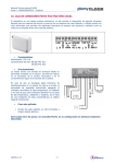
EVZ Series (Small body)
Explosion protected luminaire
Operating Instructions
Cooper Crouse-H i n d s
Cooper E l ec t ron i c T ec h n ol og i es ( S h a n g h a i ) Co. , L t d .
No. 955 Shengli Road,
East Area of Zhangjiang High-Tech Park,
Shanghai 201201
China
1. Dimensions
2. Technical data
Hazardous area specification
Type of protection: Ex de (Flameproof, Increase Safety)
ATEX classification: Group II Category 2 G
Certification Marking:
II2 G Ex d e IIC T…Gb
Ambient temperature: -40ºC~+55ºC
Temperature class: Refer to Type configuration
EC type examination
Certification No.: T V 11 ATEX 7092 X
4. Safety Instructions
This product should be installed, inspected, and maintained by a
qualified electrician only, in accordance with national regulation,
including the relevant standard and, where applicable, in acc. with
EN/IEC 60079-17 on electrical apparatus for explosive atmospheres.
The national safety rules and regulations for prevention of
accidents and the following safety instructions in these operating
instructions, will have to be observed!
IECEx Certificate No.: IECEx CQM 11.0002
Degree of protection: IP 66 acc. to EN60529/IEC60529
Approval of the production
Quality assurance: Baseefa ATEX 5952
Enclosure specification
Material of enclosure: Metal alloy aluminum without Cu
Finish: Painted polyester power coat grey
Material of glass: Tempered glass
Mounting plate: Stainless steel or painted power coat
Fasteners: All external fasteners stainless steel
Installation: Mounting bracket with aiming quadrant
Weight: Refer to Type Configuration.
Entry specification
Indirect entry: 2 M20 1.5 or 2 M25 1.5 or 2 NPT3/4” cable
entry. One entry is fitted with an Exe stopping plug.
Electrical specification
The luminaires must not be operated in Zone0 and in Zone20!
Before opening, electrical power to the luminaire must be turned
off for at lease 10 minutes!
Do not install where the marked operating temperature exceed
the ignition temperature of the hazardous atmosphere.
Do not operate in ambient temperatures above those indicated
on the luminaire nameplate.
The lumininaires shall be operated as intended and only in
undamaged and perfect conditions!
Keep tightly closed when in operation!
The technical data indicated on the lumininaires are to be
observed!
Change of the design and modifications to the luminaires are not
permitted!
Multiple, short-term switching must be observed!
Only genuine Cooper Crouse-Hinds spare parts may be used for
replacement!
Repairs that affect the explosion protection, may only be carried
out by Cooper Crouse-Hinds or qualified electrician!
Do not keep these operating instructions inside the luminaires
during operation!
Wattage: 70W/100W/150W
Voltage: 220V/230V 50/60Hz, 240V 50Hz
Lampholder: E27/E40
Insulation class: I acc. to IEC60598
Terminals capacity: 3 or 6 core conductor/cable
Solid 0.5~6mm2
Flexible 0.5~4mm2/0.5~6mm2
Lamp: High pressure Sodium/Metal Halide
3. Conformity with standards
This explosion protection luminaires meet the requirements of
EN/IEC60079-0, EN/IEC60079-1, EN/IEC60079-7, It also complies
with the EC Directives for “Apparatus and protective system for use
in explosion atmospheres”(94/9/EC).
It has been designed, manufactured and tested in accordance to
the state of the art and according to ISO 9001:2000.
The luminaires are suitable for use in explosive atmospheres,
Zone1,Zone2 according to IEC60079-10-1
IM0060.Revision 2
08/12
5. Field of Application
The ATEX category 2 G Luminaire with a separate Exe terminal box
utilizes Exde protection and IP66 sealing making it suitable for use for
potentially explosive atmospheres including ignitable gas and dust
applications. The luminaire is designed for use in Zone1/Zone21
hazardous areas in indoors and outdoors in Marine and Wet locations,
where moisture, dirt, corrosion, vibration and rough usage may be
present.
Application ambient temperature is -40ºC~+55ºC. Refer to the luminaire
nameplate for specific classification information, maximum ambient
temperature suitability and corresponding operating temperature
(T- Number).
The enclosure materials used, including any external metal parts, are
high quality materials that ensure a corrosion resistance and resistance
to chemical substances according to the requirements for use in a
“normal“ industrial atmosphere. In case of use in an extremely
aggressive atmospheres, please refer to manufacture.
Cooper Electronic Technologies (Shanghai) Co., Ltd
Page 1 of 3
6. Type configuration
Without Reflector
Watt
Std. Cat No. (W) Lamp
T Class (Gas)
Voltage
T
With Reflector
(Dust)
T Class (Gas)
T
(Dust)
Lampholder +40ºC +50ºC +55ºC +40ºC +50ºC +55ºC +40ºC +50ºC +55ºC +40ºC +50ºC +55ºC
Weight
(Kg)
EVZIS*07***
70
HPS
E27
T5
T5
T4
83
93
98
T4
T4
T4
100
110
115
EVZIM*07***
70
E27
T5
T5
T4
83
93
98
T5
T4
T4
93
103
108
10
EVZIS*10***
100
220V 50Hz
230V 50Hz
HPS
240V 50Hz
MH
220V 60Hz
HPS 230V 60Hz
MH
E40
T5
T4
T4
94
104
109
T4
T4
T4
110
120
125
11
EVZIM*10***
100
EVZIS*15***
150
EVZIM*15***
150
MH
Permissible angle of 0 /30
10
E27
T4
T4
T4
97
107
112
T4
T4
T4
112
122
127
11
E40
T4
T4
T4
113
123
128
T3
T3
T3
136
146
151
12
E27
T4
T4
T4
111
121
126
T3
T3
T3
133
143
148
12
7.4 Opening/closing the luminaire
7. Installation
7.4.1 General
The opening of luminaire always shall be
The respective national regulations IEC/EN
without voltage!
60079-14 as well as the general rules of
All gasket seals must be clean and undamaged
engineering which apply to the installation and before closing the luminaire.
operation of explosion protected apparatus will Make sure the luminaires is well closed
have to be observed!
before operation!
Do not install where the marked operating
There are Exd thread joints between the
temperature exceed the ignition temperature housing and the globe and between the
of the hazardous atmosphere!
housing and top hat!
Do not operate in ambient temperatures
Top hat has been fixed to the housing by the
above those indicated on the luminaire
manufacturer before delivery, and the Exd
nameplate!
thread joint has been tightened by the set
The improper installation and operation may screw which is not permitted to be loosen by
result in the explosion protection and
the user.
invalidation of the guarantee.
7.4.2 Terminal cover
7.2 Mounting luminaire
Unscrew the screws and remove the terminal
compartment cover.
7.2.1 Mounting the bracket
Only use the accompanying mounting bracket! Carry out the steps in reverse order to close the
luminaire.
Securely fasten the mounting bracket to a
Check all screws to ensure a secure fit
suitable base with sufficient load- bearing
(Torque for screws: 1.5 Nm).
capacity. See Fig.1 and Fig.2 for detail.
7.1 General
Fig. 1 Luminiare adjustment for
bracket mounting
Permissible angle of 0 /20
7.2.2 Adjustment of floodlight
Loosen the set screw and fixing screws to
rotate the bracket to set the required tilt angle
between 0 and 30 and 0 and 20 according
to different mounting bracket.
Re-tighten the set screw and fixing screws .
The lamp must not be illuminated when at a
distance of less than 0.5m from inflammable
material.
Fig. 2 Luminiare adjustment
for pole bracket
Fig.3 Tighten & Loose of
Globe Assembly
Prepare the conductor as
the drawing before connect
it to the earth crew.
Fig. 4 Electrical connection
IM0060.Revision 2
08/12
7.2.3 Guard/Reflector installation
Optional Reflectors
• Angle reflector RA725
• Dome reflector RD725
The optional reflectors are attached to the
luminaire as follows:
Loosen three screws on globe housing and
Position reflector over globe.
When correctly placed, three holes in reflector
will match three holes on globe housing.
Thread screws into globe housing.
Note: The same screws are used to attach
the reflector and guard. If they used
together, the reflector must be installed first.
7.4.3 Globe
Loosen the set screw in the ballast housing and
unscrew the globe from ballast housing.
To ensure that the globe assembly is in-line with
the ballast housing, rotate the globe assembly
through 180 anti-clockwise in order to accurately
line up the threads, then thread globe assembly
onto ballast housing until assembly seats firmly
against O-ring. Tighten the set screws to secure
globe housing.
Note: If globe assembly resists turning, insert a
straight blade screwdriver in jacking slot and
pry loose (see Figure 3).
7.5 Electrical connection
The electrical connection of the lamp must
only be established by qualified electricians.
Make sure the supply voltage is the same as
the luminaire voltage!
Use proper supply wiring as specified on the
nameplate of the luminaire and in this
instructions!
Excessive tightening may affect or damage the
connection.
See section 7.4 for notes on opening and closing
the luminaire. Connect cable according to the
7.3 Cable entries/blanking plugs
terminal numbering and circuit diagram.
The “Increased safety (Exe)" properties must
The conductors shall be connected with special
be preserved when, for example, using cables care in order to maintain the explosion category.
and wires of sufficient diameter. Unused holes Leads connected to the terminals shall be
shall be closed with a certified blanking plug in insulated for the appropriate voltage and this
order to establish the Exe protection category. insulation shall extend to within 1mm of the metal
The cable glands and blanking plugs should be of the terminal throat.
Ex tD certified if the whole product is Ex tD
The conductor itself shall not be damaged.
certified also. The authoritative mounting
The connectible min. and max. conductor crossguidelines for the cable glands used must be
sections shall be observed (see technical data).
observed. Mounting the selected cable entries All terminal screws, used and unused, shall be
(cable glands) acc. type and dimensions of the tightened down to between 1.2~2Nm for MK/6
main connection cable. Following their
and 0.5~0.7Nm for BK.
manufacturer instructions.
Main connection: See wiring diagram.
Cooper Electronic Technologies (Shanghai) Co., Ltd
Page 2 of 3
(Optional terminals)
Fig. 5 Wiring Diagram
(HPS/MH)
9. Maintenance/Servicing
9.1 General
The relevant national regulations which apply to the
maintenance/servicing of electrical apparatus in explosive atmospheres,
shall be observed (EN/IEC 60079-17).
The interval between maintenance depends upon the ambient
conditions and the hours of operation. The recommendations given
within EN/IEC 60079-17 for recurring checks must be observed.
9.2 Checks
During maintenance, the parts affecting the level of protection must be
checked in particular:
- Enclosure and glass for cracks and damage.
- Seals for damage.
- Terminal, screw glands and blanking plugs for secure fitting.
- The flameproof joint have to be clean undamaged, without corrosion
and perfect greased.
- To maintain the light output, clean the protective glass and reflector
Fig. 6 Family tree
periodically with a damp cloth or a mild cleaning fluid.
A complete EVZ luminaire consists of: A Housing Assy, Top hat Assy, -If this product is used in the combustible dust area, outside of enclosure
Glob Assy, a mounting bracket, with or without guard and/or reflector. must be cleaned on a regular basis to prevent accumulation of dust.
Cleaning the rests of grease and corrosion do not use sharp
metallic devices that can damage the threads of the joint, and
greasing them using appropriate grease terminally and chemically
stable with a drop point 200 like e.g.: HTL lubricant from Cooper
Crouse-Hinds!
When the housing need to be repainted, pay attention that the
flameproof joints test without any part with coating!
9.3 Lamp change
The suggested interval between lamp changes given by the lamp
manufacturer should be followed.
Disconnect power to the luminaire and allow the luminaire to cool
completely.
See section 7.4 for notes on opening and closing the luminaire. If the
luminaire was previously in operation then wait 10 mins. before opening.
Ensure that no hazardous atmosphere is present.
See section 7.6 for notes on inserting the lamp.
10. Repair/Overhaul/Modifications
10.1 General
The national regulations ENIEC60079-19 have to be observed!
Repairs and overhaul may only be carried out with genuine Cooper
Crouse-Hinds spare parts.
Before replacing or disassembling individual parts, observe the following:
Disconnect the power supply to the equipment before
maintenance/repair.
Make sure that there is no explosive atmosphere when opening the
equipment.
See section 7.4 for notes on opening and closing the luminaire.
Only use original spare parts.
If the luminaire was previously in operation then wait 10 mins.
7.6 Lamp mounting
before opening.
Only must be mounting appropriated lamps for the supplied
Repairs that affect the explosion protection, may only be carried
luminaire see indications on the nameplate of the luminaire and in
out by Cooper Crouse-Hinds or a qualified electrician in
this instructions!
compliance with the applicable national rules.
See section 7.4 for notes on opening and closing the luminaire . The
Modifications to the device or changes to its design are not
lamp must be screwed tightly into the lampholder.
permitted.
Ensure it is screwed in fully so that no sparks or other unauthorized
After carrying out repair or overhaul work, ensure that the “Exde"
operating states may occur. Protect the glass on the lamp from
properties have not been affected.
breaking when screwing in.
Assistance may also be obtained through Cooper Electronic
Technologies (Shanghai) Co., Ltd. Sales Service department,
8. Putting into operation
955 ShengLi Road, Pudong Shanghai 201201.
Prior to putting the apparatus into operation, the tests specified in the
Phone (86) 21-28993600
relevant national regulations shall be carried out.
Insulation measurements may only be carried out between PE and the
11. Disposal/Recycling
external conductor L1 (L2, L3) as well as between PE and N.
When the apparatus is disposed of, the respective national regulations
- Measurement voltage: Max. 1 kV AC/DC
on waste disposal will have to be observed.
- Measurement current: Max.10 mA
- The luminaire may only be operated when closed.
IM0060.Revision 2
08/12
Cooper Electronic Technologies (Shanghai) Co., Ltd
Page 3 of 3