1
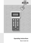
Operating Instructions Beam Control Lite Pro Contents Contents 1 Overview.................................................................................. 1 2 Initiating................................................................................... 4 3 Operation................................................................................. 5 3.1 Principles of operation ..................................................................................... 5 3.2 Standard door function menu .......................................................................... 5 3.3 Key function menu........................................................................................... 7 3.4 Group function menu....................................................................................... 9 3.5 Door special function menu ........................................................................... 11 3.6 Programming key functions ........................................................................... 17 3.7 System function menu................................................................................... 20 3.8 Cash menu.................................................................................................... 22 4 Maintenance.......................................................................... 25 5 Appendix................................................................................ 26 5.1 Example group plan....................................................................................... 26 5.2 Example room plan........................................................................................ 28 5.3 Example key plan .......................................................................................... 30 Overview 1 Overview The Beam Control Lite Pro is a portable programming and data transfer unit to configure the terminals and program the electronic keys. It is a handy, battery operated appliance and builds in the case of Dialock together with the applied terminals the Compact Solution. 1 2 3 4 1 2 3 4 Beam Control Lite Pro with integrated user software Display Keyboard Number pad The Beam Control Lite Pro allows the following functions: l Programming of the electronic keys l Allocation of group and individual locking rights l Configuration of the terminals (set room number/date/time) l Selection of the locking protocols showing the last 150 contacts at the terminals The functions of the user software are distributed over eight menu points. With the foil keyboard, the menu points are selected and for example numerical values are entered. The display consists of a four line indicator with up to 16 icons per line where the menu points, functions and entries are shown. The Keyboard The following chart gives an overview of the keyboard of the Beam Control Lite Pro. Keys Functions F1 Switch off the door, terminate the Beam Control Mode ESC Back to the initial menu F2 Switch off Beam Control Lite Pro Select menus in ascending order OK Confirm the entry Select menus in descending order Number pad Enter numerical values Programming field Switch on Beam Control Lite Pro 1 Overview General Overview of the Menu Points The function of the individual menu points is explained below. The keys F1 and F2 are active in all menu points. The initial menu appears after switching on the Beam Control Lite Pro and after ), from this menu terminating or interrupting a function. By using the arrow keys ( all further menu points can be selected. 1. Standard door function menu In the STANDARD DOOR FUNCTION MENU configuration data is set or viewed at the terminals, such as time, date and room number. In addition, the locking protocol of the terminals can be selected and transferred to a printer. The STANDARD DOOR FUNCTION MENU contains the following functions: - Read time & date from the door - Set time & date in the door - Read room number - Set room number - Read protocol from door - Send protocol to the printer - Turn off the door 2. Key function menu In the KEY FUNCTION MENU staff keys are programmed, checked and deleted. Lists can be viewed showing all staff and guest keys with locking authorisations (only in the operating mode Hotel + Personnel). The KEY FUNCTION MENU contains the following functions: - Block one staff key - Learn one staff key - Erase all staff keys - Check for a staff key - Show valid staff keys - Print list of staff keys - Read valid guest keys (service function) - Read key codes from the door (service function) - Send key codes to the door (service function) 3. Group function menu In the GROUP FUNCTION MENU group locking authorisations are set, checked and deleted at the terminal. In the Complete Solution, this menu allows the group locking schedules created with Software Personnel to be transferred from the programming unit of the PC to Beam Control Lite Pro and from there to the terminal. The GROUP FUNCTION MENU contains the following functions: - Add group in door - Remove group from door - Erase all groups in the door - Check door for one valid group - Read valid groups from door - Print list of valid groups - Read group data from the pyramid - Write group data to the door 4. Door special function menu Via the DOOR SPECIAL FUNCTION MENU the terminals are equipped with special functions and the type number of the terminal-software is selected. The menu is also used when terminals are being exchanged. The DOOR SPECIAL FUNCTION MENU contains the following functions: - Establish emergency operation keys 2 Overview - Set door back to Dialock system Door always closed mode Door always open mode Return door into normal op. mode Set up time zones Read software version of door Change lock state mode on/off Exchange lock &;transfer data 5. Programming key functions The PROGRAMMING KEY FUNCTIONS allows the direct programming of electronic keys with the Beam Control Lite Pro. With the functions of this menu, all user specific data of a key is set. The PROGRAMMING KEY FUNCTIONS contains the following functions: - Programming staff key - Read data from staff key - Fixate staff key - Put staff key in learning mode - Read cash value 6. System function menu In the SYSTEM FUNCTION MENU the settings are carried out at the Beam Control Lite Pro itself. In the Complete Solution, the functions of this menu allow data to be transferred from the programming station to the Beam Control Lite Pro. The SYSTEM FUNCTION MENU contains the following functions: - Change system date/time - Automatic shut down - Set type of transponder - Read configurat. from the pyramid - Write configurat. to the door 7. Cash menu The CASH MENU is only to be used in conjunction with the Complete Solution and the cash module. In this menu, cash terminals are set and settings are selected. Tariffs and types of transfer are defined and are transmitted to the terminal. The CASH MENU contains the following functions: - Read data from the door - Cash mode - Cash price 1 - Cash price 2/3/4 - Lock/run time - Read accounting counter - Reset accounting counter - Transfer data to the door 3 Initiating 2 Initiating 1. Insert two 9-V-block batteries (see change of batteries) 2. Press the -key. The initial menu of the Beam Control Lite Pro appears. 4 Operation 3 Operation 3.1 Principles of operation The Beam Control Lite Pro is operated via a foil keypad. A menu point or function is accessed by selecting the menu point or function with the arrow keys and by confirming the selection with the OK-key. In order to exchange data between the terminal and the Beam Control Lite Pro, the terminal has to be set to the Beam Control mode. Generally, the following steps have to be taken to program the terminals. l l Activate the Beam Control mode Transfer of data to the terminal Activate the Beam Control Mode In order to set the terminal into the Beam Control mode you require, apart for the initial use of the terminal, a privileged staff key (see function PROGRAMMING KEY FUNCTIONS). A privileged staff key is only recognised as privileged by the terminal, when it has operated the terminal at least once. Conditions: l Door Terminal must be switched on. l Wall Terminal must be connected. l Red LED must be illuminated. 1. Place the left corner of the Beam Control Lite in front of the terminal at a distance of approx. 1 - 2 cm. Both LEDs flash. 2. Place the privileged staff key in front of the terminal. Both LEDs are illuminated. The Beam Control mode is activated. The terminal can now exchange the data with the Beam Control Lite Pro. Transfer of data to the terminal The data transfer between the Beam Control Lite Pro and the terminal is carried out in the Beam Control mode. Both LEDs of the terminal have to be illuminated and the distance between the terminal and Beam Control Lite Pro must not be too large. The following steps have to be taken in order to transfer the data. 1. 2. 3. 4. 5. Switch on Beam Control Lite Pro. Select the required function. Activate the Beam Control mode. Place the Beam Control Lite Pro in front of the terminal at a distance of 5 - 10 cm. Carry out and confirm the function. If the distance between Beam Control Lite Pro and the terminal is too large or an error occurs during the data transfer, the following error message appears: IR ERROR OCCURRED. Õ Repeat the process by placing Beam Control Lite Pro closer to the terminal. 3.2 Standard door function menu Select the menu 1. Switch on Beam Control Lite Pro. key. 2. Press The following appears: STANDARD DOOR FUNCTION MENU. 5 Operation 3. Press OK-key. Function READ TIME & DATE FROM THE DOOR of the STANDARD DOOR FUNCTION MENU appears. By pressing the arrow keys, the functions of the menu point STANDARD DOOR FUNCTION MENU can be selected one by one. Read time & date from the door Select and check the date of the terminal. Õ Select function READ TIME & DATE FROM THE DOOR. Time and date of the terminal are transferred to the Beam Control Lite Pro and are shown in the display. Set time & date in the door Transfer time and date of the Beam Control Lite Pro to the terminal. Prior to this, set the data in the SYSTEM FUNCTION MENU. Õ Select function SET TIME & DATE IN THE DOOR. Time and date of the Beam Control Lite Pro are transferred to the terminal. Read room number Read the room number, which is set in the terminal. Õ Select function READ ROOM NUMBER. The room number of the terminal is shown on the display, i.e. ROOM NUMBER XY (with XY = 1). Set room number Before you set the room number, you create an index table. The example shows the possible layout of such a table. Index table room numbers Room no. Description Type no. Type description 1 Front entrance 1 External door 2 Side entrance 1 External door 3 Staff entrance 1 External door 10 Manager’s office 2 Single door 11 Sales manager 2 Single door 20 Main entrance to typing pool 3 Access to department 21 Side entrance to typing pool 3 Access to department Each terminal is given a room number of up to 4 digits. This room number is necessary to create locking schedules. Any number entered in error can be erased digit by digit with the F2-key. Together with the room number, the project code is set at the same time. This means: once the room number has been set, the terminal can only be set into Beam Control mode with a privileged key. Õ Before setting a room number, it is necessary to program a privileged staff key. 1. Select function SET ROOM NUMBER. A text appears: ENTER VALUE. 6 Operation 2. Enter the room number via the keypad. 3. Press OK-key. A text appears: ROOM NUMBER SET TO XY , i. e. with XY = 1. The room number entered is transferred to the terminal where it is stored. Read protocol from door The standard system configuration of the terminal is set such that it stores the last 150 actions. Recall the last 150 actions or settings as protocol. Õ Select function READ PROTOCOL FROM DOOR. A text appears: PLEASE WAIT. Display indication changes: PROTOCOL FOR ROOM XY, i.e. with XY = 1. The last 150 actions or settings of the terminal are stored in Beam Control Lite Pro. By using the arrow keys, the list can be browsed through or via the function SEND PROTOCOL TO THE PRINTER it can be printed out at a printer with Dialock infrared adapter. If the Beam Control Lite Pro switches off automatically after the data transfer, the protocol has to be selected again. Send protocol to the printer Print the most recently entered protocol on a printer, which is equipped with a Dialock infrared-adapter. 1. Place Beam Control Lite Pro in front of the infrared interface of the printer. 2. Select function SEND PROTOCOL TO THE PRINTER. The protocol is transferred to the printer and is printed. Turn off the door This function is equal to pressing the F1-key. Õ Select function TURN OFF THE DOOR. A text appears: DOOR IS TURNED OFF. Door terminal is switched off, Beam Control mode is terminated. 3.3 Key function menu Select the menu 1. Switch on Beam Control Lite Pro. 2. Press twice the key . A text appears: KEY FUNCTION MENU. 3. Press OK-key. The function BLOCK ONE STAFF KEY of the KEY FUNCTION MENU appears. By pressing the arrow keys, one by one the functions of the menu point KEY FUNCTION MENU can be selected. Block one staff key Withdraw the locking authorisations of a staff key. The staff key is deleted in the terminal and is no longer authorised to be used at this terminal. Any number entered in error can be erased digit by digit with the F2-key. 1. Select function BLOCK ONE STAFF KEY. A text appears: BLOCK STAFF KEY NO.: 2. Enter the number of the staff key to be blocked. 3. Activate Beam Control mode. 4. Place Beam Control Lite Pro in front of the terminal at a distance of 5 - 10 cm. 7 Operation 5. Press OK-key. A text appears: STAFF KEY BLOCKED: XY, i.e. with XY = 13. The staff key is erased from the terminal. Learn one staff key Allocate locking authorisations to a staff key directly at the terminal. The staff key has to be programmed already. Example: locking authorisations are to be allocated directly at the terminals to a previously deleted key or to a replacement key. Õ Select function LEARN ONE STAFF KEY and at the same time place the staff key to be introduced in front of the terminal. A text appears: KEY NUMBER IS LEARNED. The staff key number is stored in the terminal. Erase all staff keys Withdraw locking authorisations from all staff keys. This function does not delete the authorisations of electronic keys which are programmed with group authorisations for this terminal. Õ The terminal register is cleared. All electronic keys authorised for this terminal with group authorisation are learned again by the terminal when they are used for the first time. Individually introduced keys have to be introduced again. Õ Select function ERASE ALL STAFF KEYS. A text appears: PLEASE WAIT. The display-indicator changes: ALL STAFF KEYS ERASED. All staff keys are erased from the register of the terminal. Check a staff key Check via the staff key number, if the staff key has locking authorisations at the terminal. Any number entered in error can be erased digit by digit with the F2-key. 1. Select function CHECK FOR A STAFF KEY. A text appears: KEY-NO. TO CHECK FOR: 2. Enter the number of the staff key to be checked. 3. Activate Beam Control mode. 4. Place Beam Control Lite Pro in front of the terminal at a distance of 5 - 10 cm. 5. Press OK-key. A text appears: KEY XY LEARNED/NOT LEARNED, i.e. with XY = 13. The data in the terminal is selected and the staff key number is searched for. The display shows, if the key has locking authorisation to this terminal or not. Show valid staff keys Show list of all staff keys with locking authorisations. Õ Select function SHOW VALID STAFF KEYS. A text appears: VALID STAFF KEYS: XY, i.e. with XY = 13. The staff keys with locking authorisation are selected and stored in the Beam Control Lite Pro. The first number of the list appears on the display. By using the arrow keys, the key numbers can be shown one by one or can be printed via the function PRINT LIST OF STAFF KEYS on a printer with Dialock infrared adapter. Print list of staff keys Print the data of the staff keys which were most recently entered on the terminal on a printer with a Dialock infrared adapter. 1. Place Beam Control Lite Pro in front of the infrared interface of the adapter. 8 Operation 2. Select function PRINT LIST OF STAFF KEYS. The list of staff keys with locking authorisation is transferred to the printer and is printed. Read valid guest keys Function only to be used in the operating mode Hotel, as only in this operating mode guest keys are programmed. Show all guest keys with locking authorisations on this terminal. Õ Select function READ VALID GUEST KEYS. A text appears: GUEST KEY: XY, i.e. with XY = 3. The Guest Keys with locking authorisation are selected and are stored in Beam Control Lite Pro. The first number of the list appears on the display. By using the arrow keys, the key numbers can be shown one by one. Read key codes from the door This function simplifies the configuration of various terminals, where the same staff keys have locking authorisation. The staff keys are approved at one terminal, selected and simply transferred to the next terminal. The function READ KEY CODES FROM THE DOOR stores the key data of the staff keys authorised at this terminal in Beam Control Lite Pro. Õ Select function READ KEY CODES FROM THE DOOR. A text appears: PLEASE WAIT. Display indication changes back to the function READ KEY CODES FROM THE DOOR. The key data of the staff keys is selected and is stored in Beam Control Lite Pro. Via the function SEND KEY CODES TO THE DOOR, the data can be transferred to a further terminal. Send key codes to the door This function simplifies the configuration of various terminals, where the same staff keys receive a locking authorisation. The data of the staff keys, which were previously received from another terminal via the function READ KEY CODES FROM THE DOOR , are transferred to the current terminal. With this function, any staff keys which are learned at a terminal can quickly receive locking authorisations for other terminals as well. Õ Select function SEND KEY CODES TO THE DOOR. A text appears: PLEASE WAIT. Display indication changes back to function SEND KEY CODES TO THE DOOR. The staff key data is transferred to the terminal. 3.4 Group function menu Select the menu 1. Switch on Beam Control Lite Pro. three times. 2. Press the key A text appears: GROUP FUNCTION MENU. 3. Press OK-key. Function ADD GROUP IN DOOR of the GROUP FUNCTION MENU appears. By pressing the arrow keys, the functions of the menu points GROUP FUNCTION MENU can be selected one by one. Add group in door Before a staff key has locking authorisation at a terminal, it must be allocated to a group. It receives the locking authorisation at all terminals which belong to this group. 9 Operation Keys of a department are gathered into a group. The group can be named for better clarity. Please create an index table for your group numbers. The example shows the possible layout of such a table. Index table of group numbers Group no. Group name Rooms 1 General Manager 1, 2, 3, 10, 11, 20, 21 2 Departmental Manager 1, 2, 3, 11 3 Typing pool 3, 20, 21 Inform the terminal of the group numbers via the function ADD GROUP IN DOOR. Any number entered in error can be erased digit by digit with the F2-key. 1. Select function ADD GROUP IN DOOR. A text appears: GROUP SECTOR START: 2. Enter the number of the first group, which needs to be added to the terminal. 3. Press OK-key. A text appears: GROUP SECTOR STOP: 4. Enter the number of the last group, which needs to be added to the terminal. If only one group is added, the start number equals the stop number. 5. Activate Beam Control mode. 6. Place Beam Control Lite Pro in front of the terminal at a distance of 5 - 10 cm. 7. Press OK-key. A text appears: GROUP XY – XY LEARNED. The group numbers are transferred to the terminal and are stored as locking authorised. In order to enter further groups, please repeat the steps described above. Erase group from door Withdraw the locking authorisation for the terminal from a group. Any number entered in error can be erased digit by digit with the F2-key. 1. Select function ERASE GROUP FROM DOOR. A text appears: ENTER GROUP TO BE ERASED. 2. Enter the number of the group which needs to be erased. 3. Activate the Beam Control mode. 4. Place Beam Control Lite Pro in front of the terminal at a distance of 5 - 10 cm. 5. Press OK-key. A text appears: GROUP XY ERASED, i.e. with XY = 1. The group entered is erased from the terminal. All staff keys belonging to this group lose their locking authorisation at this terminal. Erase all groups in the door Withdraw the locking authorisation for the terminal from all groups. Õ Select function ERASE ALL GROUPS IN THE DOOR. A text appears: ALL GROUPS IN DOOR ERASED. None of the groups has locking authorisation at this terminal. Check door for one valid group Check the locking authorisation of a group and show this in the display. Any number entered in error can be erased digit by digit with the F2-key. 1. Select function CHECK DOOR FOR ONE VALID GROUP. A text appears: GROUP NUMBER TO CHECK FOR: 10 Operation 2. Enter the number of the group, whose locking authorisation needs to be checked at the terminal. 3. Press OK-key. A text appears: GROUP XY IS VALID / NOT VALID. The data in the terminal is selected and the group number is searched for. The display shows, whether or not the group has locking authorisations at this terminal. Read valid groups from door Select the list of all groups with locking authorisations at the current terminal. Õ Select function READ VALID GROUPS FROM DOOR. A text appears: VALID GROUPS: XY, i.e. with XY = 1. The groups authorised at this terminal are selected and are stored in Beam Control Lite Pro. The first number of the list appears on the display. all group numbers with locking authorisation are shown one by one. With the key Via the function PRINT LIST OF VALID GROUPS the list can be printed at a printer with Dialock infrared adapter. Print list of valid groups Print the list, which is stored in Beam Control Lite Pro, showing all groups with locking authorisations at a certain terminal, on a printer with a Dialock infrared adapter. 1. Place Beam Control Lite Pro in front of the infrared interface of the adapter. 2. Select function PRINT LIST OF VALID GROUPS. The list of authorised groups is transferred to the printer and is printed. Read group data from the pyramid Use this function only in the Complete Solution, as group data is entered via the PCsoftware group data which is then transferred from the programming station at the PC to Beam Control Lite Pro. Scan the group data, which was entered at the PC, from the programming station into the Beam Control Lite Pro. 1. Start the Beam Control mode in the PC-software. 2. Place Beam Control Lite Pro at the infrared interface of the programming unit. 3. Select function READ GROUP DATA FROM THE PYRAMID. A text appears: TRANSMISSION ACTIVE. The group data is transferred to Beam Control Lite Pro where it is stored. Write group data to the door Use this function only in the Complete Solution, as the group data viewed previously by the programming unit is transferred to the terminal. 1. Select function WRITE GROUP DATA TO THE DOOR. A text appears: PROGRAMMING DOOR. 2. Press OK-key. The first number of the group locking schedule is suggested. 3. If this number is the number of the room, press the OK-key. The group locking authorisations are transferred to the terminal. 4. In order to change the room number, press the F2-key. Õ Select the room numbers via the arrow keys or enter it directly via the keypad. 5. Press OK-key. The group locking authorisations of the selected room number are transferred to the terminal. 3.5 Door special function menu Select the menu 1. Switch on Beam Control Lite Pro. 11 Operation four times. 2. Press the key A text appears: DOOR SPECIAL FUNCTION MENU. 3. Press OK-key. The function ESTABLISH EMERGENCY OPERATION KEYS of the DOOR SPECIAL FUNCTION MENU appears. By pressing the arrow keys, one by one the functions of the menu point DOOR SPECIAL FUNCTION MENU can be selected. Establish emergency operation keys Use this function only in the operating mode Hotel. If in the operating mode Hotel the software does not function, i.e. due to a power cut, the PC is not available. In order for the arriving guests to occupy the rooms despite this, the respective door terminal is temporarily set to operating method Stand Alone and emergency keys are created. These keys are valid until the terminal is re-set into standard mode via the function SET DOOR BACK TO DIALOCK SYSTEM. Afterwards, any keys with locking authorisation have to be re-issued via the Software Hotel. 1. Select function ESTABLISH EMERGENCY OPERATION KEYS. A text appears: KEYS ARE NOW BEING LEARNED. The green LED flashes. 2. One by one, place the guest keys to be learned at the terminal. 3. Once all keys are learned, wait until the LED switches off. The keys receive the locking authorisations for the terminal. Set door back to Dialock system Use this function only in the operating mode Hotel. Re-set the terminal from the emergency operating mode to the normal mode. Õ Select function SET DOOR BACK TO DIALOCK SYSTEM. A text appears: LOCK IN DIALOCK SYSTEM. The terminal is re-set into the normal mode. The previously learned guest keys are no longer valid. These have to be re-programmed via the Software Hotel. Door always closed mode The door is always locked, even if valid keys want to operate the terminal. This function is used, if access needs to be denied to other persons during temporary absence. The door remains locked until the terminal is re-set into normal mode. Õ Select function DOOR ALWAYS CLOSED MODE. A text appears: DOOR IS ALWAYS CLOSED. The door is locked and cannot be opened, even with authorised keys. Door always open mode The door is always unlocked, even valid keys cannot lock it. This function is used, when a door should always remain unlocked, i.e. for public access. This function is valid until the terminal is re-set to the normal mode. Õ Select function DOOR ALWAYS OPEN MODE A text appears: DOOR ALWAYS OPEN. The door is unlocked and cannot be locked, even with authorised keys. Return door into normal op. mode Re-set the terminal into normal operating mode. The function DOOR ALWAYS CLOSED MODE or DOOR ALWAYS OPEN MODE is cancelled. Õ Select function RETURN DOOR INTO NORMAL OP. MODE. A text appears: DOOR IS IN NORMAL MODE. The terminal is set into the locking mode, which is set in the basic configuration. All keys with locking authorisation are valid again. 12 Operation Set up time zones Creation of time zones, during which groups have locking authorisation. The time zone is registered with a function. This function can be controlled through and entrance and / or exit condition. The entrance conditions are of no importance for door terminals. The entrance condition for wall terminals depends on additional appliances, which are possibly connected. As a standard, two entrances can be equipped with additional appliances, i.e. entrance 1 with an opening sensor in the reception, entrance 2 with a light barrier. Entrance 3 can optionally be designed for a further additional appliance. Entrance Condition Significance 0 No additional appliances are connected, terminal opens with the key. 1 The additional appliance connected to entrance 1, i.e. a door opener, opens in addition to the key during the set time zone. Example: The terminal can be opened via the door opener in the reception as well as via all keys with locking authorisation. 2 The additional appliance connected to entrance 2, i.e. a light barrier, opens in addition to the key during the set time zone. Example: The terminal can be opened via the light barrier as well as via all keys with locking authorisations. 3 Optional connection for a third additional appliance. The exit condition defines the locking mode. Exit Condition Door Terminal Wall Terminal 1 Normal bolt action, the terminal unlocks and locks again after a few seconds. Release of the relay 1 with generally defined operating method of the terminal. 2 Change of the locking mode, terminal in toggle mode. Change of the locking mode, terminal in toggle mode. 3 Without function. Switch relay 2. 4 Without function. Switch relay 3. If the function SET UP TIME ZONES is selected, various sub-functions enable the conditions to create time zones. Time zones are defined by the week days and times, when access is granted. These sub-functions are grouped as follows: l l l l Setting of locking actions without key Definition of the cash conditions Definition of the locking authorisations General locking authorisations The following tables allow an overview of the sub-functions of the function SET UP TIME ZONES. 13 Operation Sub-functions to set up time zones Function Description No zone No time zone is created. All keys which are authorised at this terminal have free access at all times. Creation of locking actions without key Function Description Open The door terminal unlocks during the first activation within the time zone and locks only during the first activation outside this time zone. Doors, which are controlled by wall terminals are unlocked during this time zone. The entry OPEN can depend on the entrance condition. The exit condition can be selected. Lock cycle The door terminal unlocks during the time zone stated after activation without the need for a key. This function is only sensible for the wall terminal, if it is connected with an entrance condition (i.e. I = 1, door opener). Without the entry of an entrance condition, the opening cycle of the door changes constantly. The exit condition can be selected. Change status During this time zone, the terminal is set to the togglemode. This setting is only sensible for wall terminals with an entrance condition. This setting is only sensible for wall terminals if these are connected to an entrance condition (i.e. I = 1, door opener). The exit condition must be 1. Definition of the cash conditions This function can only be used in the Complete Solution, as only there keys can be allocated with the cash function. Function Description Price from option During this time zone, the terminal transfers the price which is defined by the time zones option 1 - 4. Price from rate During this time zone, the terminal transfers the price which is defined by the setting cash price 1 - 4. Price guest opt. During this time zone, the terminal transfers the price, which is defined by the time zone option. The cash transfer is only carried out for guest keys. The guest key must be programmed on page 1. Price staff opt. During this time zone, the terminal transfers the price, which is defined by the staff option. The cash transfer is only carried out for staff keys. The staff key must be programmed on page 1. 14 Operation Definition of the locking authorisations The entrance condition controls the exit condition. Function Description Only staff Access only for staff keys during this time zone. Only priv. staff Access only for privileged staff keys during this time zone. Only staff w. opt. Access only for staff keys with the respective option during this time zone. Only staff w. grp. Access only for staff keys with the respective group during this time zone. Guest w. opt. + staff Use only in the Complete Solution. Access only for guest keys with the respective option for this time zone and for staff keys. Only guest w. opt. Use only in the Complete Solution. Access only for guest keys with the respective option for this time zone. General locking authorisations Function Description All staff (opt.) General locking authorisation for staff keys with the respective option for this time zone. The keys do not require a further locking authorisation. They are not stored in the terminal. The locking authorisation is not blocked when a replacement key is issued. With option 0, all staff keys have locking authorisation, independent from the programmed conditions. All guests (opt.) General locking authorisation for guest keys with the respective option for this time zone. The keys do not require a further locking authorisation. They are not stored in the terminal. The locking authorisation is not blocked when a replacement key is issued. With option 0, all guest keys have locking authorisation, independent from the programmed conditions. Each terminal can be configured with four time zones. All time zones are configured in the same way, only the menu points time zone (1, 2, 3, 4) are different. The programming procedure is described in the example of time zone 1. A time zone consists of a time interval and the indication of the weekday. The time interval can be entered from 0.00h to 0.00h (day and night). Õ Activate the days when the time zone should be valid, i.e. Su, Mo, Tu, We, Thu, Fr, Sa, Su, Ho (Ho = bank holiday). 1. Select function SET UP TIME ZONES. A text appears: READ DATA FROM DOOR. The time zones set in the terminal are transferred to the Beam Control Lite Pro. 2. Press key A text appears: SET UP TIME ZONE 1. 3. Press OK-key. A text appears: TIME ZONE 1 FROM/TO. 15 Operation 4. With the keys F1 and F2 move the cursor from hour to minute. Set hours and minutes with the arrow keys. The minutes can be set in intervals of 15 minutes. 5. Press key F2 until the cursor sits in the empty line below the time interval. activate the days, when the time zone should be valid. With the 6. With the key key F2 move from one day to the next. The days appear in the above mentioned sequence from Su to Ho. 7. Press OK-key. It appears: THE FUNCTION OF THE SUB-MENU, WHICH IS SET FOR TIME ZONE 1. If no time zone is created, a text appears: NO ZONE. 8. Select the function with the arrow key. 9. With the key F2 move the cursor to position option. 10. Press key . A text appears: ENTER OPTION. 11. Possibly enter option number. 12. Press OK-key. 13. With the key F2 move the cursor to position I = Input (entrance condition). 14. Press key . A text appears: ENTER INPUT. 15. Enter the entrance number if an additional appliance is connected and if the time zone should refer to the additional appliance. 16. Press OK-key. 17. With the key F2 move the cursor to position O = Output (exit condition). 18. Press key . A text appears: ENTER OUTPUT. 19. Enter the exit number for the setting of the locking mode or the relay number during this time zone. 20. Press OK-key. A text appears: SET UP TIME ZONE 1. The time zone conditions set are stored in Beam Control Lite Pro. 21. Via the arrow key, select function TRANSFER DATA TO THE DOOR. 22. Press OK-key. The time zone settings are transferred to the terminal. Repeat the complete procedure to set further time zones. With the function SET UP TIME ZONES, the set time zones can be checked. Read software version of door Show the current software version of the terminal on the display. Õ Select function READ SOFTWARE VERSION OF DOOR. A text appears: SOFTWARE VERSION: X.XX. The number of the software version, with which the terminal is equipped, is shown. Change lock state mode on/off The function state change at the terminal can be switched on or off. on = yes: During each operation with an authorised key, the terminal changes the status from unlocked to locked or from locked to unlocked. The terminal is in togglemode. off = no: During operation with an authorised key, the terminal unlocks and automatically locks again after a few seconds. The terminal is in normal mode. 1. Select function CHANGE LOCK STATE MODE ON/OFF. A text appears: STATE CHANGE YES/NO. The set status is shown. 2. Press arrow keys. Change between on and off of the status change mode. 16 Operation 3. Press OK-key. A text appears: STATE CHANGE TURNED ON/OFF. The terminal is set into the normal mode or toggle mode. Exchange lock &;transfer data Transfer all settings stored from one terminal to an exchange terminal. The exchange data in Beam Control Lite Pro is lost, when the appliance switches off. Õ Have the exchange terminal ready. Õ Possibly increase the time interval for automatically switching off your Beam Control Lite Pro in the SYSTEM FUNCTION MENU. 1. Select function EXCHANGE LOCK &;TRANSFER DATA. A text appears: PLEASE WAIT. The display changes, when the settings of the door terminal are stored in the Beam Control Lite Pro. A text appears: WRITE DATA IN LOCK. 2. Place Beam Control Lite Pro in front of the exchange terminal. Both LEDs are illuminated. 3. Press OK-key. A text appears: PLEASE WAIT. The date and time set are shown on the display. The previously selected data is transferred to the exchange terminal as a 1:1 copy. All keys which had locking authorisations at this terminal automatically receive the locking authorisation at the exchange terminal. They do not have to be re-introduced. 3.6 Programming key functions The locking authorisations of the staff keys are defined via groups. Each programmed key must belong to a group. Please check in your group plan, which key number belongs to which group. Please create an index table for your key numbers. The example shows the possible layout of such a table. Index table key numbers Key-no. Name Department 1 Mrs. Maier Management floor 1 2 Mr. Walter Departmental Manager workshop 2 3 Mr. Winkler Departmental Manager typing pool 2 4 Mr. Müller Typing pool 3 5 Mrs. Schmitt Typing pool 3 6 Mrs. Schulze Typing pool 3 7 Mrs. Zanker Canteen 4 17 Group-no. Operation Select menu 1. Switch on Beam Control Lite Pro. five times. 2. Press key A text appears: PROGRAMMING KEY FUNCTIONS. 3. Press OK-key. The function PROGRAMMING STAFF KEY of the PROGRAMMING KEY FUNCTIONS appears. By pressing the arrow keys, one by one the functions of the menu point PROGRAMMING KEY FUNCTIONS can be selected. Programming staff key This menu point allows the direct programming of staff keys with the Beam Control Lite Pro. Each key has up to 4 programmable pages. Each page of the key is considered to be an individual key, i.e. each page should be allocated with its own key number. The first page of each key should always be programmed first. Any number entered in error can be deleted digit by digit with the F2-key. You can exit from this function at any time with ESC .This terminates the programming procedure and does not change existing data. 1. Select function PROGRAMMING STAFF KEY. A text appears: WHICH PAGE (1 - 4)? 2. Enter the page of the key, which needs to be programmed. 3. Press OK-key. A text appears: ENTER THE KEY NUMBER. 4. Enter the number of the key which needs to be issued. 5. Press OK-key. A text appears: LEARNING MODE YES/NO (). The learning mode of the key can be switched on or off. During the setting LEARNING MODE YES the key can be learned directly at the terminal. This setting is required in order to issue a replacement key for example. 6. Change setting by pressing the arrow keys. 7. Press OK-key. A text appears: PRIVILEGED YES/NO (). The key to be programmed is issued as privileged key or as normal staff key. A privileged key allows the user to carry out settings at the terminals with the Beam Control Lite Pro or to unlock doors, although these are locked from inside. For a privileged key to become valid, it has to be used once at the terminal after programming. 8. Change the current setting by pressing the arrow keys. 9. Press OK-key. A text appears: ENTER GROUP. The key must be allocated to a group and is then authorised at all terminals belonging to this group. 10. Enter the group number. 11. Press OK-key. A text appears: TIME ZONE START (). If the electronic key should have access authorisation only during a certain time, set here the start of the time zone in intervals of 15 minutes. 12. Set the time by pressing the arrow keys. 13. Press OK-key. A text appears: TIME ZONE STOP (). The end of the time zone is specified. 14. Set the time by pressing the arrow keys. 18 Operation 15. Press OK-key. A text appears: WEEKDAYS. SuMoTuWedThuFrSaHo (Ho = Holiday) If the key needs to be valid on certain weekdays only, specify here the valid days. 16. With the keys F1 and F2, move the cursor to the day when no/a locking authorisation should exist. Õ Press keys or . The day is set or deleted. 17. Press OK-key. A text appears: ENTER THE OPTION. The key can be programmed with an option number (255 options are possible). The options can have been set during the time zone setting. They contain for example a valid time period, when the key has locking authorisation. 18. Enter the option number. 19. Press OK-key. A text appears: DATE OF EXPIRY (DDMMYY). An expiry date can be set for the key, when it automatically loses its locking authorisation. The entry is carried out in two digits each in the sequence of day, month, year. 20. Entry = 0. The key is valid for an unlimited period. 21. Entry = date. The key loses its locking authorisation on the specified day. 22. Place the key to be programmed over the programming field of the Beam Control Lite Pro. 23. Press OK-key. A text appears: KEY WILL BE PROGRAMMED. After a few seconds a text appears: KEY IS PROGRAMMED. The key is programmed with the data entered. Via the function READ DATA FROM STAFF KEY the entries can be checked. Read data from staff key Select key-data and show it on the display. 1. Select function READ DATA FROM STAFF KEY. A text appears: WHICH PAGE (1 - 4)? 2. Enter the page of the key which should be read. 3. Press OK-key. A text appears: READING KEY. 4. Place the key over the programming field of the Beam Control Lite Pro. The key data is selected and is shown on the display. The following data is visible: No = key number Gr = locking group number Op = options number SMTWTFSH = weekdays (Sunday to Saturday + bank holiday) 00:00 - 00:00 = set time zone P = key is privileged L = key is in memory mode Until dd mon yyyy = expiry date of the key Key is not programmed on the specified page. Õ A message appears: KEY NOT PROGRAMMED. Fixate staff key Remove key from the learning mode. A learned staff key must be fixated in order to be used. 19 Operation 1. Select function FIXATE STAFF KEY. A text appears: WHICH PAGE (1 - 4)? 2. Enter the page of the key which has to be fixated. 3. Press OK-key. A text appears: KEY WILL BE FIXATED. 4. Place the key over the programming field of the Beam Control Lite Pro. The display changes: KEY IS FIXATED. The key is removed from the learning mode and has now locking authorisations for the terminal. Put staff key in learning mode Set one page in the key into learning mode, so that the key can be learned individually at the terminal. Fixate the key again after this procedure. 1. Select function PUT STAFF KEY IN LEARNING MODE. A text appears: WHICH PAGE (1 - 4)? 2. Enter the page of the key which needs to be set into learning mode. 3. Press OK-key. A text appears: KEY WILL BE SET TO LEARNING. 4. Place the key over the programming field of the Beam Control Lite Pro. The display changes: KEY IS SET LEARNING. The key can now be learned directly at the terminal and afterwards be fixated again via the function FIXATE STAFF KEY. Read cash value This function can only be used sensibly in the system version Complete Solution, as only in this version cash values are programmed onto the key via the PC-software. The cash value booked onto a key is selected and is shown on the display. 1. Select function READ CASH VALUE. A text appears: READING KEY. 2. Place the key over the programming field of the Beam Control Lite Pro. The cash-value currently booked onto the key is shown. The following data appears: Value = existing cash-value Counter 1 = number of operations of terminals which are configured as booking counter 1 Counter 2 = number of operations of terminals which are configured as booking counter 2 Rate = allocation to a certain tariff group 3.7 System function menu Select menu 1. Switch on Beam Control Lite Pro. six times. 2. Press the key A text appears: SYSTEM FUNCTION MENU. 3. Press OK-key. The function CHANGE SYSTEM TIME of the SYSTEM FUNCTION MENU appears. By pressing the arrow keys, one by one the functions of the menu point SYSTEM FUNCTION MENU can be selected. Change system time Display and change the date and time of the Beam Control Lite Pro. 1. Select function CHANGE SYSTEM TIME. The set date and time are displayed. 20 Operation 2. Press OK-key. A text appears: DATE (DDMMYY). 3. Enter the date with two digits each: day, month and year. 4. Press OK-key. A text appears: TIME (HHMMSS). 5. Enter the time in two digits each: hour, minute and second. 6. Press OK-key. The date and time are stored in the Beam Control Lite Pro and are shown on the display. Automatic shut down In order to save the batteries of the Beam Control Lite Pro, the appliances shuts down automatically when not in use. Set the time in seconds, after which the Beam Control Lite Pro shuts down automatically. 1. Select function AUTOMATIC SHUT DOWN. A text appears: AUTOMATIC OFF AFTER XY SECONDS, (i.e. with XY = 60). 2. In order to change the seconds, delete the entry displayed digit by digit with F2 3. Enter the time, after which the Beam Control Lite Pro should switch off. 4. Press OK-key. The time is stored in the Beam Control Lite Pro. Set type of transponder Õ Standard setting: MP without password (MP = Multi Page). This setting must only be changed, if a locking system is run by transponders of the older generation. Read configurat. from the pyramid This function can only be used sensibly in the system version Complete Solution. An error message appears in the system version Compact Solution. Transfer the data created on the PC for the current configuration database for Dialock terminals to the Beam Control Lite Pro. 1. Start the Beam Control mode in the PC-software. 2. Place Beam Control Lite Pro in front of the infrared interface of the programming unit. 3. Select function READ CONFIGURAT. FROM THE PYRAMID. The configuration data for the terminal is stored in the Beam Control Lite Pro. Data can be transferred via the function WRITE CONFIGURAT. TO THE DOOR onto the terminal. Write configurat. to the door The data stored in the Beam Control Lite Pro of the current configuration database are transferred to the terminal. This function can only be used sensibly in the system version Complete Solution. In the system version Compact Solution, this application can lead to malfunctions of the terminal. Õ Use this function only following instructions from a Dialock technician. Õ Select function WRITE CONFIGURAT. TO THE DOOR. The configuration data is transferred from the Beam Control Lite Pro to the terminal. 21 Operation 3.8 Cash menu Use this menu only in connection with the system version Complete Solution, as only there the respective keys can be equipped with cash functions. Guest doors as well as general doors can be configured as cash terminals. There are two different types of cash transfers. 1. Cash transfer – an amount is deducted from the cash value booked onto a key, if the key has no other locking authorisation. 2. Counter-transfer– there are two counters on the transponder, which are increased by 1 in case of authorised use. Which counter is increased depends on the configuration of the terminal. The number of operations is later viewed at the cash till and is charged. Select menu 1. Switch on Beam Control Lite Pro. seven times. 2. Press the key A text appears: CASH MENU. 3. Press OK-key. The function READ DATA FROM THE DOOR of the CASH MENU appears. By pressing the arrow keys, one by one the functions of the menu point CASH MENU can be selected. Read data from the door Read the cash data stored at the terminal and store the data in the Beam Control Lite Pro. Õ Select function READ DATA FROM THE DOOR. All current cash settings are transferred to the Beam Control Lite Pro. By selecting the function CASH MODE the set mode of the terminal is displayed. Cash mode In this function, the terminal is configured as cash terminal. The menu CASH MODE offers various configuration possibilities via a sub-menu. The following table shows an overview of the configuration possibilities. 22 Operation Sub-functions to the function Cash mode Function Description Free The Terminal is not being configured as cash terminal. Cash rate The terminal deducts the amount which is defined by the tariff-programming of the key. Price 1 The terminal deducts the amount which is defined by the setting "Cash Price 1" at the terminal. Time zone 1 std. Time zone 1 standard means: the terminal deducts the amount, which is defined in connection with the time zone setting. If no time zone applies, the amount of setting "Cash Price 1" is being deducted. Time zone no std. Time zone no standard means: The terminal deducts the amount, which is defined in connection with the time zone setting. If no time zone applies, nothing is deducted and access is not granted. Counter 1 This function can only be used in the operating mode Hotel in the system version Complete Solution. The cash terminal is configured as operating counter 1. Every operation is stored in the key and is viewed for subsequent invoicing. Counter 2 This function can only be used in the operating method Hotel in the system version Complete Solution. The cash terminal is configured as operating counter 2. Every operation is stored in the key and is viewed for subsequent invoicing. This configuration makes sense, when the amount to be invoiced differs from the amount of operating counter 1. Only one function can be selected for each terminal. 1. Select function CASH MODE. The sub-function which was set last of the CASH MODE appears. 2. Select the required sub-function with the arrow keys. 3. When reaching the required sub-function, press the OK-key. The selected cash mode is stored in the Beam Control Lite Pro. Transfer the selected cash mode to the terminal via the function WRITE DATA TO THE DOOR. Cash price 1 Value for the cash price 1 is set. 1. Select function CASH PRICE 1. 2. Enter the value via the keyboard, i.e. 500 = 5.00 Pounds. The unit is defined at the PC in the Windows system parameters. 3. Press OK-key. The value is registered as standard value. If the tariff system is set, this value is defined as tariff 1. The set tariff is transferred to the terminal with the function WRITE DATA TO THE DOOR. Cash price 2 - 4 The value for the cash price 2, 3, 4 is set. 1. Select function CASH PRICE 2 - 4 . 2. Enter the value for the tariff 2, 3 or 4 via the keyboard. 3. Press OK-key. These values are registered for the tariffs 2, 3 or 4. The set tariffs are transferred to the terminal via the function WRITE DATA TO THE DOOR . 23 Operation Lock/run time Define the time in minutes, during which a terminal can be operated more than once, without making a further booking. 1. Select function LOCK/RUN TIME. 2. Enter the time via the keyboard. Up to 45 days can be set in 1-minute intervals. Õ Actual value = 0 The set tariff is deducted, each time the key is used. Õ Actual value = XY min. During this time, the terminal can be used again without any deduction. 3. Press OK-key The set value is stored in the Beam Control Lite Pro. With the function WRITE DATA TO THE DOOR the time value is transferred to the terminal. Read accounting counter Select bookings. This function is only sensible, if the terminal is configured as accounting counter. Õ Select function READ ACCOUNTING COUNTER . All accounts are transferred from the terminal to the Beam Control Lite Pro and are shown on the display. Reset accounting counter Set the counter back to zero after the bookings have been selected. Õ Select function RESET ACCOUNTING COUNTER. The accounting counter of the terminal is set to zero. Write data to the door Transfer cash data, which was entered in the Beam Control Lite Pro to the terminal. Õ Select function WRITE DATA TO THE DOOR. The cash data is handed over to the terminal. 24 Maintenance 4 Maintenance Change of batteries Do not dispose of batteries through your household waste! Õ Dispose of batteries in an environmentally friendly manner, i.e. via a communal collection point. 1. 2. 3. Beam Control Lite Pro rear view Battery compartment Screw 1. Open the battery compartment at the rear of the Beam Control Lite Pro with a screw driver. 2. Remove the batteries from the push-button holder. 3. Insert two new 9-V-block-batteries. 4. Close the battery compartment and simply fix it with screws. 25 Appendix 5 Appendix In this appendix you find examples and forms in order to create group-, room- and key-plans. The examples should explain the plans and simplify the administration of the Compact Solution. The Compact Solution is installed as follows: 1. Set operating mode Personnel (Dialock technician). 2. Introduce the group numbers to the terminal. 3. Set time and date. 4. Set room numbers at the terminal. 5. Program the keys and introduce these to the terminal. 5.1 Example group plan The staff keys in the operating mode Personnel are defined by the group numbers. Groups must be created of members, who receive identical locking authorisations. It is important to notice, that each key should only belong to one group, even if all 4 pages are being programmed. l l l Group no. Enter all allocated group numbers. Group name Enter the group names, which are hidden behind the group number. Selfexplanatory names should be chosen. Rooms Enter room numbers, to which the groups receive locking authorisations. Group no. Group name Rooms 1 Managing Director all 2 Sales Manager Numbers of the rooms, to which the sales managers have locking authorisations. 3 Personnel typing pool Numbers of the rooms, to which the personnel of the typing pool has locking authorisations. 4 Personnel canteen Numbers of the rooms, to which the canteen personnel has locking authorisations. 5 Sales personnel Numbers of the rooms, to which the sales personnel has locking authorisations. 6 Personnel technical department Numbers of the rooms, to which members of the technical department have locking authorisations. 26 Appendix Group plan Group no. Group name 27 Rooms Appendix 5.2 Example room plan Each terminal is identified via a room number. l l l l Room no. Enter all allocated numbers, which belong to the total system. Description Enter the name of the door or room, which is hidden behind the room number. Self-explanatory names should be chosen. Type no. Number the type of the doors. Type description Enter the description of the door, which is hidden behind the type number. Room no. Description Type no. Type description 1 Front entrance 1 External door 2 Side entrance 1 External door 3 Staff entrance 1 External door 10 Managing Director’s office 2 Single door 11 Sales Manager 2 Single door 20 Main door to typing pool 3 Access to department 21 Side door to typing pool 3 Access to department 28 Appendix Room plan Room no. Description 29 Type no. Type description Appendix 5.3 Example key plan Each operator receives an electronic key, which is programmed on one or more pages. In order to check, which key has been given to whom, the key numbers are entered in the key plan. Each programmed page of the key should be given an individual key number. l l l l Key no. Enter the allocated key numbers. Name of operator Enter each operator, who receives a key. Department The specification of the department simplifies the identification of the operators, i.e. in order to differentiate two members of staff with the same name. Group no. Enter the group, to which the operator belongs. In the chart, the group number refers to the group plan. Key no. Name Department Group no. 1 Mrs. Maier Management floor 1 2 Mr. Walter Workshop Manager 2 3 Mr. Winkler Manager of typing pool 2 4 Mr. Müller Typing pool 3 5 Mrs. Schmitt Typing pool 3 6 Mrs. Schulze Typing pool 3 7 Mrs. Zanker Canteen 4 30 Appendix Key plan Key no. Name Department 31 Group no. Operating instructions 732.29.472 The reprint of the operating instructions, even extracts, or copying of the illustrations and drawings as well as copying of the layout are prohibited. No liability is accepted for printing errors or errors occurred during the creation of the operating instructions. We reserve the right for technical changes and changes of availability. Status 12.00 Copyright Häfele GmbH & Co Adolf-Häfele-Strasse 1 · D-72202 Nagold Postfach 1237 · D-72192 Nagold Telefon +49 (0) 74 52 / 95-0 Telefax +49 (0) 74 52 / 95-200 E-Mail: [email protected] · www.haefele.de