1
Universal Controller
Operating Instructions/
Descriptions
controller 2000/2020/5350
R
Gm
bbHH
Automatisierungstechnik
Contents
Page
Order Code....................................................................................................... 3
Connection diagram ........................................................................................ 3
Installation instructions .................................................................................... 5
Technical data ................................................................................................. 6
Display and keyboard ....................................................................................... 8
Adjusment of parameter values ....................................................................... 9
Function levels................................................................................................ 10
Configuration level.......................................................................................... 11
Parameter level .............................................................................................. 18
Operating level ............................................................................................... 22
Hints for using the serial interface .................................................................. 24
Process value output (as casting device) ..................................................... 25
Error messages .............................................................................................. 26
Accessories (to be ordered seperately)......................................................... 26
Parameterlist .................................................................................................. 27
Please read this operating manual carefully before starting up.
Observe the installation and connecting instructions
Order Code
2000 (48x96 mm)
2020 (96x48 mm)
-1 Power supply: AC 230 V (internal jumper: AC 115 V)
-2 Power supply DC 24 V
Output
-A switching controller Relay (max. AC 250V, 3A) and voltage, bistable
(0/18VDC)
-B switching and steady working controller Relay (max AC 250V, 3A)
and voltage, bistable (0/18VDC) and current (steady 0/4...20mA)
and voltage (steady 0...10VDC)
-0 without interface
-1 with interface serial RS485
Accessories
FK Front-adapter 96x96mm (plastics)
FA Front-adapter 96x96mm (aluminium)
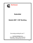
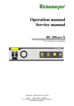
Connection diagram 2000-1-...-0
Control output, continuous (Option)
-
+
21
22
+
L1 (+)
Power
Supply
N (-)
OUT U/I
20
+
10
Control output OUT 1
2-point/continous: "heating" or "cooling"
Heat-cool-controller: "heating"
Three-point-step-controller: "open"
RLoad OUT 2
19
9
+
18
8
17
7
RLoad OUT 1
+
OUT 1
Control- or alarm output OUT 2
2-point /: alarm 2
Heat-cool-controller: "cooling"
Three-point-stept-controller: "close"
S2
16
6
15
5
14
4
13
3
S1
OUT 2
OUT 3
Alarm 1
12
2
11
1
+
+
0...10V
-
+J
Pt100
(RTD)
23
A
Setpoint setting
S1: open = SP1 valid
0/4...20mA S1: closed = SP2 valid
+
TC
-
Adjustment lock (LOC)
S2: open = Adjustment lock only via “software
code”
S2: closed = Adjustment locked (according to the
chosen software code)
Inputs
24
B
Serial Interface RS485 (Option)
Important: It is not permitted to connect the grounds of the sensor-, bistable voltageand continuous – outputs with each other!
3
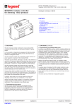
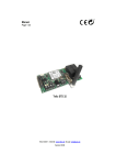
Connection diagram 5350
S2 S2
1
2
-
3
+
4
15
Pt100
-
TC
+
5
6
9
10
11
12
13
14
16
OUT 3
17
18
N.C.
19
S1
20
S2
7
8
-
0..10V 0/4..
+
20mA
+
R Load OUT 1
R Load OUT 2
+
A
Serial interface RS485
(Option)B
+
Control output, continuous
(Option)-
OUT 2
21
22
N.C.
23
OUT 1
24
25
N.C.
26
N.C.
27
28
Power
Supply
N
(-)
L1 (+)
Control output OUT 1
2-point / continuous controller: "
“heating or "cooling"
Three-point-step-controller: "heating"
Three-point-step-controller: "open"
Control- or alarm output OUT 2
2-point-/continuous controller: Alarm 2
Heat cool controller: "cooling"
Three-point-step-controller: "close"
Setpoint setting
S1: open = SP1 valid
S1: closed = SP2 valid
Adjustment lock (LOC)
S2: open = Adjustment lock only via
"softwarecode"
S2: closed = Adjustment locked
(according to the
chosen softwarecode)
It is not permitted to connect the grounds of the sensor-, bistable voltagesand continuous – outputs with each other!
4
Installation instructions
Make certain that the devices described here are used only for the
intended purpose. They are intended for installation in control panels.
The controller must be installed so that it is protected against impermissible
humidity and severe contamination.
In addition, make sure that the permitted ambient temperature is not exceeded.
The electrical connections must be made according to the relevant german VDE
directives and locally applicable regulations.
Transducer cables and signal lines (e. g. logic output lines) must be laid physically
separated from control lines and main voltage supply cables (power cables).
If using a thermocouple sensor, the compensation cables should be laid directly
to the controller terminals.
Transducers must be connected only in compliance with the programmed range.
Physical separation between controller and inductive loads is recommended.
Interference from contactor coils must be suppressed by connecting adapted
RC-combinations parallel to the coils.
Control circuits (e. g. for contactors) should not be connected to the power supply
terminals of the controller.
Important
Before operation, the unit must be configurated for its intended purpose (e.g.
controller type, sensor-type, alarm adjustment etc.).
Please see configuration level.
Device installation
The instrument (2000-1-A-0 / 200-1-B-0) is constructed with plug-in technology. The
instrument can be drawn out of the housing together with the front panel. This,
however, can only be done after the instrument has been isolated from its power
supply.
5
Technical data
Inputs:
- TC:
Built-in internal compensation point and protection against sensor breakage and
incorrect polarity.
Re-calibration not required for a line resistance of up to 50 Ohm.
Calibration accuracy:
£ 0,25 %
- Pt 100 (RTD):
2- or 3-wire connection possible.
Built-in protection against sensor breakage and short-circuit.
Maximum permissible line resistance by 3-wire connection: 80 Ohm
Sensor current:
£ 0,5 mA
Calibration accuracy:
£ 0,2 %
- Standard signals:
DC 0 to 20 mA, 4 to 20 mA (Ri < 10 Ohm)
DC 0 to 10 V, (Ri > 100 k-Ohm)
Calibration accuracy:
£ 0,2 %
Linear eror:
£ 0,2 %
Influence of the ambient temperature: £ 0,01 % / K
- Setpoint switch-over:
external potential-free contact (switches voltage of app. DC 24 V, max. 1 mA)
Control outputs:
- OUT 1: Relay, (n/o contact) max. AC 250 V, 3 A at cos-phi = 1and bistable voltage,
DC 0/18 V, max. 10 mA, short-circuit proof
- OUT 2: Relay, (changeover contact) max. AC 250 V, 3 A at cos-phi = 1 and bistable
voltage, DC 0/18 V, max. 10 mA, short-circuit proof
- OUT 1: Stetig (nur bei Version - 611)
Continuous (additionally for version -611-)Output type (current or voltage) is
determined automatically, dependent on load.
DC 0/4...20 mA, load of
< 500 Ohm
DC 0/2...10 V, load of
> 1 k-Ohm
Linearity:
< 1,5 %
Calibration accuracy
< 1,0 %
Delay:
app. 2 s
Alarm outputs:
- OUT 2: Relay, (changeover contact) max. AC 250 V, 3 A at cos-phi = 1Only for 2point-controller (heat-only or cool-only) configuration and continuous-controller
configuration.
- OUT 3: Relay, (changeover contact) max. AC 250 V, 3 A at cos-phi = 1
7-Segment-display:
10 mm red (Process)
7,6 mm red (Set)
6
Data protection:
EAROM, semiconductor memory
Serial interface:
RS 485 (Option)
EMC:
CE-marked according to EN 50081-2 and EN 50082-2
Power supply:
- AC 230 V, (internal jumper: AC 115 V , jumper from "a-b" (230 V) to "b-c" (115 V))
± 10 %, 48 to 62 Hz
Typ 2000-1-A-0/2000-1-B-0 : Pull out the device out of the housing together with the front panel
Type 5350: Remove rear cover, then pull out half the PCB’s by holding the orange
plug of the CPU-Board.
The jumper on the powersupply-PCB is now accessible.
Attention! This device has to be connected to fused power supply only.
- AC 24 V, ± 10 %, 48...62Hz
-
DC 24 V, ± 20 %, permissable residual ripple max. 5 % r.m.s.
app. 4,5 VA power consumption
Connections:
Screw terminals, Protection mode IP 20 (DIN 40050), Insulation class C
(connector / terminal board – 5350)
Permissible operating conditions:
Operating temperature: 0...50 °C / 32...122 °F
Storage temperature:
-30...70 °C / -22...158 °F
Climate class:
KWF DIN 40040;
equivalent to annual average max. 75 % relative humidity. No condensation.
Housing:
Format:
(2000-1-A-0)
48 mm x 96 mm (DIN 43700), Installation depth 112 mm
96 mm x 48 mm (DIN 43700), Installation depth 112 mm
(2000-1-B-0)
96 mm x 96 mm (DIN 43700), Installation depth 122 mm
(5350)
Panel cutout :
Unit:
Material:
Enclosure:
45 mm + 0,6 mm x 92 mm + 0,8 mm (2000-1-A-0)
92 mm + 0,8 mm x 45 mm + 0,6 mm (2000-1-B-0)
92 mm + 0,8 mm x 92 mm + 0,5 mm (5350)
replaceable from front (2000-1-A-0, 2000-1-B-0)
Noryl, self-extinguishing, non-drip, UL 94-V1
IP 20 (DIN 40050),
IP 54 front side
Weight:
ca. 450 g (2000-1-A-0)
ca. 450 g (2000-1-B-0)
ca. 600 g (5350)
Subject to technical improvements!
7
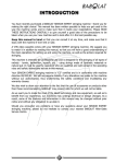
Display and keyboard
Control output"heizen"
“heating/ "auf"
/ open”
Stellausgang
Control output"kühlen"
“cooling/ /"zu"
“close”
Alarm2 2
Stellausgang
oderorAlarm
Alarm 1
5 030 10
2
OUT 1
0
OUT 3
OUT 2
240
Istwert oder Parameterkürzel
PROCESS
Sollwert
2 "aktiv"
Setpoint
2 “active”
Sollwertrampe
Setpoint ramp "aktiv"
“active
Scan up Sets parameter
Werte
to higher
valuevergrößern
Scan down Sets parameter
Werte verkleinern
to lower value
SET 2
240
Setpoint
or parameter
value
Sollwert
oder
Parameterwert
P
E
Parameter key
Parametertaste
SET
+
-
Entertaste
(quittieren)
Enter key (confirmation)
Alarm 1
Control
output “cooling”
or Alarm
Stellausgang
"kühlen"/ “close”
/ "zu" oder
Alarm 22
Sollwert
Setpoint2 2"aktiv"
“active”
Control
output “heating”
/ “open”
Stellausgang
"heizen"
/ "auf"
Setpoint ramp"aktiv"
“active”
Sollwertrampe
52 03 2200
1
2
3
OUT
SET 2
Setpoint
or Parameterwert
parameter value
Sollwert
oder
Process
value
or abbreviation
Istwert
oder
Parameterkürzel
PROCESS
P
240
+
SET
-
240
E
value
value Decrease
Parametertaste
Werte vergrößern
/ verkleinen
Parameter
key Increase
Enter key
Entertaste
(quittieren)
8
Alarm 1
ControlStellausgang
output “cooling”
/ “close”
or Alarm
"kühlen"
/ "zu" oder
Alarm 22
Control Stellausgang
output “heating”
/ “open”
"heizen"
/ "auf"
5350
Actual Istwert
value oder
or parameter
token
Parameterkürzel
240
PROCESS
OUT 1
Sollwert
2 "aktiv"
Setpoint
2 “active”
Setpoint
ramp “active
Sollwertrampe
"aktiv"
240
SET 2
SET
OUT 2
OUT 3
Setpoint
parameter
value
Sollwertoroder
Parameterwert
P
Parametertaste
Parameter key
+
-
E
Werte vergrößern / verkleinen
Entertaste (quittieren)
Increase value Decrease value
Enter key
Adjustment of parameter values
Adjustment of chosen parameter to lower or higher setting. Short
operation = single-step adjustment, longer operation = quick-scan.
When the parameter adjustments have been altered but not
entered, the display will flash bright/dark.
E
Confirmation of the pre-selected value and storage with powerfail
protection. Four decimal points appear briefly as a control of this
function
or
Sets the parameter back to the originally stored value.
P
or
Any
alteration made to the parameter, that is not confirmed (Enter
or
key) within approx. 30 seconds, is not accepted and the
parameter returns to its originally stored value.
9
Function levels
The operation of the controller is divided into three levels.
- Operating level
- Parameter level
- Configuration level
Two seconds after switching on the unit, the controller is automatically in the operating
level.
Within the operating level the set-points, the set-point ramp and the alarm values can,
in succession, be displayed by pressing P and adjusted by pressing the + and -keys.
Within the parameter level the values are adjusted to suit each
individual process. This level is reached by simultaneously pressing
the P and E keys.
.
Within the configuration level the controller type, input type, range, alarm behaviour
and output type can be pre-selected. This primary information has to be entered before
taking the controller into operation. The configuration level is reached by simultaneously
pressing the P and E keys for a period of approx. 5 seconds.
The display of each single parameter within the parameter and configuration levels, and
their adjustment, are made in the same fashion as within the operating level. After either
pressing the E key for approx. 1 second, or waiting for a period of approx. 30 sec., the
unit returns automatically to the operating level (display of process and set-point
values).
press
1s
E
or
automatically after 30s
power on2s
OPERATING
LEVEL
‡
‡
P
+
E
PARAMET ER
LEVEL
Sp1
Y
P
P
¬
€
Conf
½
©
¸
t
Cout
~
³
P
}
š
P
¦
Sp/>
¬
t
1 Ly
€
ƒ
P
‡
CONFIGURATION
LEVEL
¸
Sp2
¬
P
+
E
5s
•
ƒ
°
P
2 Ly
Sen
P
P
¦
‡
¸
™
©
P
Sp/<
‡
¬
º
Ž
P
AL 1
”
¦
€
P
P
”
~
Opt
«
P
°
P
AL 2
¦
~
Ofst
š
†
¦
LOC
~
P
P
ˆ
°
t
2000-1-A-0
„
€
•
The values on the following pages, included in braces, apply only to controllers
equipped with a serial interface.
For more details look at the separate interface description.
10
Configuration level
Display
"Process"
Parameter
ConF
controller configuration
{ 80H, 8H, r/w }
Parameter display "Set"
[ex works]
2P h
2-point or continuous controller:
"heating"
2-point or continuous controller:
"cooling"
2-point or continuous controller:
"cooling, non linear characteristic line" *)
3-point-controller: "heating - off - cooling"
3-point-controller: "heating - off - cooling,
cool with non-linear characteristic line" *)
3-point-step-controller: "open - neutral - close"
2P c
2Pnc
3P
3Pnc
3PSt
*) non-linear cooling:
For cooling a "cooling"-control rating with linear or non linear
characertistic line (e. g. evaporative cooling
from water) can be chosen.
corrected
output ratio
100 %
linear
non-linear
10
40100 %
calculated output ratio
C0ut
Configuration of Outputs
{ 81H, 8H, r/w }
OUT 1 (control-output) und
OUT 2 (control- or alarm-output A2)
ir2r
ib2r
ic2r
i c. 2 r
ir2b
ib2b
ic2b
i c. 2 b
ir2c
i r 2 c.
ib2c
i b 2 c.
OUT1:
Relay
bistable
0...20mA/0...10V
4...20mA/2...10V
Relay
bistable
0...20mA/0...10V
4...20mA/2...10V
Relay
Relay
bistable
bistable
OUT2:
Relaiy
Relay
Relay
Relay
bistable
bistable
bistable
bistable
0...20mA/0...10V
4...20mA/2...10V
0...20mA/0...10V
4...20mA/2...10V
11
Configurations level
display
"Process"
parameter
SEn
sensor-configuration
{ 1AH, 1H, r/w }
Adjustment range display "Set"
[ex works]
PI°C
PI°F
P2°C
P2°F
P3°C
P3°F
P4°C
P4°F
P8°C
P8° F
Pt 100,
Pt 100,
Pt 100,
Pt 100,
Pt 100,
Pt 100,
Pt 100,
Pt 100,
Pt 100,
Pt 100,
-50,0...100,0 °C
-58,0...212,0 °F
-90,0...205,0 °C
-130,0...401,0 °F
-199...100 °C
-326...212 °F
0...400 °C
32...752 °F
0...800 °C
32...1472 °F
L4°C
L4°F
L8°C
L8°F
J8°C
J8°F
t4°C
t4°F
E7°C
E7°F
n1°C
n1°F
51°C
51°F
r1°C
r1°F
TC Fe-CuNi (L),
TC Fe-CuNi (L),
TC Fe-CuNi (L),
TC Fe-CuNi (L),
TC Fe-CuNi (J),
TC Fe-CuNi (J),
TC Cu-CuNi (T),
TC Cu-CuNi (T),
TC NiCr-CuNi (E),
TC NiCr-CuNi (E),
TC NiCr-Ni (K),
TC NiCr-Ni (K),
TC Pt10Rh-Pt (S),
TC Pt10Rh-Pt (S),
TC Pt13Rh-Pt (R),
TC Pt13Rh-Pt (R),
0 - 20
4 - 20
10 d c
current DC 0...20 mA
current DC 4...20 mA
voltage DC 0...10 V
0...400 °C
32...752 °F
0...800 °C
32...1472 °F
0...800 °C
32...1472 °F
0...400 °C
32...752 °F
0...700 °C
32...1292 °F
0...1200 °C
32...2192 °F
0...1600 °C
32...2912 °F
0...1600 °C
32...2912 °F
If the input configuration is changed, the following parameters are all reset (setting in brackets), and
need to be re-adjusted: Set-points (OFF); Ramps (OFF); Alarms (OFF); control sensitivity (0); sensor
offset value (OFF); lower set-point limit (min: display range bottom end); upper set-point limit (max:
display range top end).
CONP
Configuration of compensation point
{ 03H, 0H, r/w }
int; 0...60 °C
int; 32...140 °F
[int]
Adjustment of used compensation point. If an external compensation point
is in use, the appropriate temperature has to be set here. The adjustment
has to be made in degree Celsius or in degree Fahrenheit according to the
input configuration. This parameter is only available if input configuration is
a thermocouple sensor
12
Configuration
display
"Process"
parameter
Adjustment range display "Set"
[ex works]
The following parameters are only valid for standard signal inputs (DC 0-20 / 4-20 mA, DC 0-10 V). The
difference between the bottom end of the display range and the top end must amount to a minimum of
100 units, and a maximum of 2000 units. By adjustment of one of the aboveparameters, the other will
automatically follow in case of need.
r dP
decimal points
{ 1DH, 1H, r/w }
0; 1; 2
[1]
r Hi
display range top
{ 1FH, 1H, r/w }
r Lo...9999
[100,0]
r Lo
display range bottom end -999 ...r Hi
{ 1EH, 1H, r/w }
SPHi
upper setpoint
limit
{ 2CH, 2H, r/w }
SPLo...Meßbereichsende
SPLo
lower set-point limit
{ 2BH, 2H, r/w }
Meßbereichsanfang...SPHi
[0,0]
[400]
[0]
13
Configuration level
display
"Process"
parameter
Adjustment range display "Set"
[ex works]
CoAI
Alarm 1-config.
{ 34H, 3H, r/w }
OFF
_ _ -I
_ J – 2
- N – 3
- _ _ 4
- L - 5
- U - 6
N - 7
Switching b ehaviour: Alarm outp ut signal con tact
Alarm OFF
signal contact (SC) off-on
limit contact (LC) off-on
limit comparator (LCP) off-on-off
signal contact (SC) on-off
limit contact (LC) on-off
limit comparator (LCP) onn-off-on
limit comparator (LCP) off-on-off
with start-up suppression
Switching b ehaviour: Alarm outp ut limit cont act
LC
SC
on
off
off
on
Configuration:
4
1
Process value
Setpoint
Swit ching behaviour: Alarm output limit comparator
on
off
off
on
Setpoint
Configuration:
5
2
Process value
Switching behaviour: Alarm output limit compar ator
+ start-up suppression
LCP
off
on
off
on
off
on
Setpoint
Configurat ion:
3
Configurat ion:
LCP
on
off
on
off
7
6
Setpoint
Process value
The limit comparator is adjusted and
displayed relative to the set-point.
The selected value is effective below
and above the set-point
Process value
The alarm relay of the limit comparator with
Start-up suppression is activated when
the controller is first switched on.
It is only then deactivated when the process
value has been within, and left, the O.K. zone.
on: Relay „activated“ or bistable voltage output „high“
off: Relay “non active” or bistable voltage output “low”
If a set-point ramp has been programmed, the alarms that are relative to the set -point (signal contact, limit
comparator) follow the set-point up the ramp.
Please note: In case of sensor error the alarms react in the same way as range over ride.
The alarm contacts therefore do not offer protection agains all types of plant breakdown.
With this in mind, we recommend the use of a second, independent monitor unit.
CoA2
Alarm configuration
{ 35H, 3H, r/w }
see CoA1 (Alarm 1-configuration)
14
Configuration level
Display
"process"
parameter
display "Set"
[ex works]
Only for 2-point controller (heating) or continuous controller (heating) or 3-point controller - configuration.
S oft start ( general function):
Process value
SP
SoSP
Soti
dependant on So Y
Ti me
For this purpose the bistable voltage output of the controller must be chosen to actuate
SSR relays.
During the soft start the controllers output response is limited to a pre-selected ration, in
order to achieve as low baking out of high performance heat cartridges.
Simultaneously the ouput clock frequency is quadrupled. Once the process value
reaches the soft start set point, it remains stable at this value for a pre-selected holdduration time. At the end of this period the process value rises to the valid set-point.
This results in a slower, more regular heating period
If the soft start is active, the controllers autotune function cannot be operated.
If a set-point ramp has been programmed, the soft start has priority, and the ramp will
only become active after the soft start has been completed.
The soft start cannot be selected if the controller is configurated as a 3-point step
controller.
So
y
output ratio
{ 6AH, 6H, r/w }
[OFF], 10...100%;
OFF: soft start inactive,
parameters SoSP and Soti of no importance
S o S P
set-point
{ 6BH, 6H, r/w }
SPLo...SPHi [0]
S o t i
hold duration time
{ 6CH, 6H, r/w }
[OFF]; 0,1...10,0 min
15
Configuration level
display
"process"
parameter
display "Set"
[ex works]
H A n d
manual output ratio
{ 62H, 6H, r/w }
[OFF], Auto
If manual operation is activated, an "H" is displayed as the first digit in the "set" display,
followed by the valid output ratio. This ratio can be manually altered in steps of 1% ( +
and -keys). The confirmation succeeds without of E.
Setting: "OFF": non active (automatic operation)
Setting "Auto":
In event of sensor break the controller automatically maintains the last valid output ratio
as the actuating signal. A few seconds after the sensor break has been rectified, the
controller returns to automatic operation and calculates the required output ratio. An
additional signal can be issued in the event of sensor break, if the alarm contacts are
programmed accordingly.
Setting "NAn":
The controller now operates only as an actuator; the temperature control is no longer
active..
Achtung!
By altering from controller operation to manual operation (Setting controller maintains the
last valid output ratio as the actuating signal.Under the following circumcances, the output
ratio is 0%:
- if the output ratio at time of sensor break was 100%,
- if the controller is working along a set-point ramp,
- if the control deviation was more than 0.25% of the total range at the time of sensor
break,
- if Xp = OFF
- if the softstart was active at the time of sensor break.
This parameter is only available when the controller is configurated as a 3-point Stepp
controller.
C o 5 b
Behaviour in the
event of sensor break
{ 8AH, 8H, r/w }
OFF
out2
out1
OUT 1 + 2 off
OUT 1 off-, OUT 2 on
OUT 1 on-, OUT 2 of
L O C
Security lock
{ 85H, 8H, r/w }
OFF
PC
-SPI
ALL
lock inactive
parameter- and conf.- level locked
all parameters apart from set-point 1 locked
all parameters locked
All locked parameters can be selected and read, but not altered.
This adjustment cannot be changed if the external switch S2 is closed
16
Configuration level
display
"process"
parameter
display "Set"
[ex works]
The following parameter apply only to controllers equipped with a serial
interface
Adr
Unit address 1 .... 255
{ 8FH, 8H, r/w }
[1]
Using this adress, a host computer system can communicate with the
controller. Every controller must have an individual address..
Attention! A maximum of 32 controllers can be connected to a RS 485
bus.
BAud
Baudrate
{8DH, 8H, r/w }
OFF
0. 3
0. 6
1. 2
2. 4
4. 8
9. 6
19. 2
38. 4
serial interfaces off
300 Baud
600 Baud
1200 Baud
2400 Baud
4800 Baud
9600 Baud
19200 Baud
38400 Baud
The Baud-rate displays the data transfer speed, with which one bit is transferred from
the transmitter to the receiver. For further details please see the separate interface
description.
For
Data format
{ 8EH, 8H, r/w }
7EI
/oI
7E2
7o2
7n2
8E1
8 o1
8n1
8n2
7 data, even,
7 data, odd,
7 data, even,
7 data, odd,
7 data, none,
8 data, even,
8 data, odd,
8 data, none,
8 data, none,
1 stop bit
1 stop bit
2 stop bits
2 stop bits
2 stop bits
1 stop bit
1 stop bit
1 stop bit
2 stop bits
With this parameter the data format is determined. For further details see the separate
interface description
5310
Figure of
device family
{ 01H, 0H, r }
- - - -
end of the config. level
17
parameter level
The following parameters apply to 2-point and heat-cool controller configuration
display
"process"
parameter
display "Set"
[ex works]
Y
Valid output ratio
-100...100 %
{ 60H, 6H, r }
The output ratio display shows the momentarily calculated output ratio. It cannot be
altered. The display is in percent of the installed performance capability for heating or
cooling. Output ratio for cooling is shown as a negative value..
I Ly
OUT 1-output ratio limit
{ 64H, 6H, r/w }
2 Ly
OUT 2- output ratio limit
0...100 % [100]
{ 69H, 6H, r/w }
(only by heat-cool-controller configuration)
A limitation of the output ratio is only necessary when: -the heating energy supply is
grossly over-dimensioned compared to the power required, or -to turn off a control
output (setting: 0 %). Under normal circumstances no limitation is needed (setting:
100 %). The limitation becomes effective, when the controllers' calculated output
ratio is greater than the maximum permissible (limited) ratio.
Attention! The output ratio limitation does not work during autotuning
I P
OUT 1-Xp Prop.range
{ 40H, 4H, r/w }
0...100 % [100]
OFF; 0,1...100,0 %
[3,0]
If Xp = OFF, the next parameter to follow ist (control sensitivity)
I d
OUT 1-Tv D-Anteil
{ 41H, 4H, r/w }
OFF; 1...200 s
[30]
I J
OUT 1-Tn I-Anteil
OFF; 1...1000 s
[150]
{ 42H, 4H, r/w }
INormally the controller works using PID control action. This means, controlling without
deviation and with practically no overshoot during start-up. Control action can be altered in
its structure by making the following adjustments to the parameters
a. no control action, on-off (setting : Xp = OFF)
b. P-action (setting: Tv und Tn = 0)
c. PD-action (setting: Tn = 0)
d. PI-action (setting: Tv = 0)
e. PID-action
I C
OUT 1-cycletime
0,5...240,0 s
[15,0]
{ 43H, 4H, r/w }
The switching frequency of the actuator can be determined by adjusting the cycle time.
This is the total time needed for the controller to switch on and off once.
a) Relay outputs: cycle time > 10 s
b) Bistable outputs 0,5...10 s.
18
parameter level
display
"process"
parameter
display "Set"
[ex works]
I 5d
Adjustment of the control sensitivity output OUT 1
(only if Xp = OFF, no control action)
sensitivity Sd
OFF; 0,1...80,0
{ 47H, 4H, r/w }
OFF; 0,01...8,00
OFF; 0,001...0,800
[0,1]
1)
2)
Sd
80,0
-40,0
on
+40,0
off
Setpoint
Pro ces s value
The following parameters apply only to the configuration of heat-cool controllers
Sh
Switch point interval
{ 46H, 4H, r/w }
OFF; 0,1...80,0
OFF; 0,01...8,00
OFF; 0,001...0,800
[OFF]
1)
2)
This parameter raises the set-point (switch-point) for the cooling output by
the displayed value. It can help to reduce the switching frequency between
the heating and cooling outputs, if this is too high. Simultaneous activation
of the heat and cool outputs is not possible.
2 P
OUT 2-Xp cool P-range
{ 50H, 5H, r/w }
OFF; 0,1...100,0 %
[6,0]
If Xp = OFF, the next parameter to follow is (contr. sensitivity for OUT 2).
1)
2)
2 d
OUT 2-Tv
{ 51H, 5H, r/w }
OFF; 1...200 s
[30]
2 J
OUT 2-Tn
{ 52H, 5H, r/w }
OFF; 1...1000 s
[150]
2 C
OUT 2 cycletime
{ 53H, 5H, r/w }
0,5...240,0 s
[15,0]
2 Sd
Adjustment of the control sensitivity OUT 2
(nur wenn Xp = OFF, ohne Rückführung)
Schaltdifferenz Sd
OFF; 0,1...80,0
{ 57H, 5H, r/w }
OFF; 0,01...8,00
OFF; 0,001...0,800
[0,1]
1)
2)
Valid for ranges with a mantissa of one digit
Valid for Rangeswith a mantissa of two digits
19
Parameter level
display
"process"
parameter
displa "Set"
[ex works]
The following parameters apply only to the configuration of 3-point step
controllers
Output
"close"
Output
"open"
Sh
Sd
Sd
on
off
Setpoint
Process valu e
3-point step controllers use PI control action in combination with motor
actuators. It is important, that Sh should be several times larger that Sd.
Switching frequency is dependant on the pre-selected feedback values..
P
Xp
{ 40H, 4H, r/w }
OFF; 0,1...200,0 %
[10,0]
t S
Motor actuating time
{ 41H, 4H, r/w }
5...800 s
[40]
t n
set time
{ 42H, 4H, r/w }
0,5...80,0 min
[3,0]
Sd
Sh
1)
2)
Control sensitivity
{47H, 4H, r/w}
OFF; 0,1...80,0
OFF; 0,01...8,00
OFF; 0,001...0,800
Switch-point interval
{ 46H, 4H, r/w }
OFF; 0,1...80,0
OFF;0,01...8,00
OFF;0,001...0,800
[0,1]
1)
2)
[0,1]
1)
2)
Valid for ranges with a mantissa of one digit
Valid for ranges with a mantissa of two digits
20
Parameter level
display
"process"
parameter
display "Set"
[ex works]
O P t
Autotune
{ 88H, 8H, r/w }
[OFF]
Autotuning not active
on single autotune cycle, upon command
Auto
automatic triggeriing of the autotune every time the controller is
switched on, if the momentary
difference between the set-point
and the process value is larger
than 7% of the total range.
The tuning algorithm determines the characteristic values within the
controlled process, and calculates the valid feedback parameters (Xp, Tn,
Tn) and the cycle time (C = 0.3 x Tv) of a PD/I controller for a wide section
of the range
If the controller is used as a heat-cool controller, the determined
parameters for heating are also adopted for cooling. Here though the value
of Xp-range for cooling is doubled..
Autotuning activates during start-up shortly before the set-point is reached.
The setpoint must amount to at least 5 % of the total range. If activated
after the set-point has already been reached, the temperature will first drop
by approximately 5 % of the total range, in order to detect the exact
amplification of the process. The tuning algorithm can be activated at any
time by selecting the option Opt=on and pressing E. An adjust of output
ratio limit is not considered.
X
W
autotune on
t
The optimization is time limited to 2 hours. If no usable control parameter
are found, the optimization is stopped.
- if soft-start is active
- if the controller is in manual operation or
- if a sensor break occures.
OFSt process value
{18H, 1H r/w}
Off ;-999.1000
Off;-99,0...100,0
Off ;-9,99...10,00
COFFJ
1)
2)
This parameter serves to correct the input signal, e.g. for:
-the correction of a gradient between the measuring point and the sensor tip;
-line resistance balancing of 2-line Pt100 (RTD) sensors;
-correction of the control deviation when using P or PD action.
If for example the offset value is set to +5 °C, then the real temperature
measured by the sensor (when the process is balanced) is 5 °C less than
the set-point and the displayed process values.
21
Operating level
display
"process"
parameter
ProcessValue
{ 21H, 2H, r/w }
display "Set"
[ex works]
set-point 1
Off, SPLl...SPHi
4)
[0]
Basic operating positions
If set-point 1 is set to "OFF..", the controller switches to stand-by. The set display then
shows "OFF". All main outputs are switched off,and the alarms are deactivated.
All parameters can be displayed and altered during stand-by.
Attention! Altering between control operation and manual operation is available by
simultaneously pressing the + and -keys for a period of approximate two seconds.
This adjustment is not stored with powerfail protection.
Only applicable to 3-point Stepp controller configuration
Hand
Manual operation
{ 8CH, 8H, r }
Off, On
[OFF]
Off: Normal control operation of the unit.
On: The unit now works only as an actuator.
The first parameter shown in the process display of the operating level is the
momentarily valid process value. The word “Hand” appears in the set display (instead of
the set-point). The outputs can now be manually activated by pressing either the + key
(for OUT 1 ) or the – key (for OUT 2)
The next parameter to appear is “SP 1”, the set-point. This set-point has no influence
while the controller is being operated manually, although it can be adjusted for later
application.
SP2
Sollwert 2
{ 22H, 2H, r/w }
Off;SPLo...SPHi 4)
[Off]
The second set-point is active when the external contact S1 is closed. The
corresponding LED on the front panel lights up, and the second set-point is shown in
the display.
Please note, that the value of the second set-point cannot be changed in the basic
operating position of the level. In order to change the value the parameter SP2 has to
be selected.
22
Operating level
display
"process"
parameter
display "Set"
[ex works]
Process value
SP2
SP1
S1
S1 Ti me
S1
A programmed ramp is always activated when the set-point is altered or
when the main supply is switched on.
The ramp constructs itself out of the momentary process value and the
preselected set-point. If the ramp is active the corresponding LED lights up
on the faceplate. The ramp can be activated for both set-point 1 and setpoint 2.
By programming the second set-point accordingly a set-point profile can
be optained (please see example above).
If a set-point ramp has been programmed, the soft start has priority, and
the ramp will only become active after the soft start has been completed.
SP
Rising ramp
{2FH, 2H, r/w}
OFF; 0,1...100,00 units./min
OFF; 0,01...10,00 units./min
OFF; 0,001...1,000 units./min
SP
Falling ramp
{ 2DH, 2H, r/w }
OFF; 0,1...100,0 units./min
OFF; 0,01...10,00 units./min
OFF; 0,001...1,000 units./min
Alarm 1
{ 38H, 3H, r/w }
Signal contact
OFF; -999...1000
OFF; -99,9...100,0
OFF; -9,99...10,00
AL I
Limit comparator
OFF; 1...1000
OFF; 0,1...100,0
OFF; 0,01...10,00
[OFF]
1)
2)
[OFF]
1)
2)
[OFF]
1)
2)
1)
2)
Limit contact
OFF; bottom end to top end range
The range of adjustment id dependent on the sensor and the alarm
configuration. Both have to be set in the configuration level.
AL 2
Alarm 2
for adjustments see Aarm 1
{ 39H, 3H, r/w }
The alarm 2 is only available if the controller is programmed as a 2-point or
continuous controller in the configuration level.
1) Valid for ranges with a mantissa of one digit
2) Valid for ranges with a mantissa of two dgits
23
Hints for using the serial interface
The following parameters apply only to controllers equipped with a serial interface
Status word 1 reports errors or alarm states ascertained by the controller.
Status word 1
{70H, 7H, r}
Bit 0 = 1: System error
Bit 1 = 1: Sensor error
Bit 2 = 0: no function
Bit 3 = 1: reset-control
A reset was triggered during operation. The
controller automatically resets bit 3 to 0 once
status word 1 has been read by the computer
Bit 4 = 0:
Bit 5 = 1:
Bit 6 = 1:
Bit 7 = 1:
No function
Alarm 1 triggerdd
Alarm 2 triggered
Set-point ramp active
Status word 2 gives an overview of the operating state of the controllers. The computer can specify
different operating states for the controller. If status word 2 is manipulated by the computer, bit 0
must always be set to '1' (remote controller operation). The controller remains then in remote
operation.
Exception: controller ON/OFF can also be edited in local operation.
If the controller is switched back to local operation by the computer, bit 0 of the status word 2 may
only be edited
Status word 2
{78H, 7H, r/w}
Bit 0 = 0:
1:
Bit 1 = 0:
1:
Bit 2 = 0:
1:
Bit 3 = 0:
1:
Bit 4 = 0:
Bit 5 = 1:
Bit 6 = 1:
Bit 7 = 1:
controller operation remote or local
controller operation remote
automatic mode (controller mode)
manual mode (actuator mode)
autotune off
autotune on
controller switched off
controller switched on
no function
setpoint 1 valid
setpoint 2 valid
no function
Attention!
Status word 2 cannot be stored with powerfail protection. An eventual 'power off' can be checked via
bit 3 (status word 1). Afterwards status 2 must be set again.
The selection of the valid setpoint via interface is only done in remote operation. In case of local
operation the selection is controlled via the external contact S1.
Status word 2 is available for reasons of compatibility with older devices.
We, however, recommend the application of appropriate individual parameters 8B H, 88 H, 21 H and
22 H.
24
Process value output: (as casting-device)
Corresponding to the process value the controller generates a scalable signal (0/4...20mA; 0...10V)
which is available on the terminals 21/22 (13/14 by 5350).
Technical data
- Process value output
Output type (current or voltage) is determined automatically, dependent on load.
DC 0/4...20 mA, (load of ? 500 Ohm)
DC 0/2...10 V, (load of ? 1 k-Ohm)
linearity: < 1,5 %
delay:
ca. 2 s
·
The secon alarm is unapplicable.
Parameter „CoA2“ und „AL2“ are omitted.
·
The configuration of OUT 1 and OUT 2 in the configuration level is modified.
Note: now OUT 1 and OUT2 cannot be used as a continuous output
COut
·
configuration
of outputs
Ir2r
ib2r
ir2b
ib2b
OUT1:
Relay
bistable
Relay
bistable
OUT2:
Relay
Relay
bistable
bistable
Additional parameters in the configuration level:
PrcC
configuration of
process outputs
0-20
4-20
0...20mA / 0...10V
4...20mA / 2...10V
PrcH
output range; top end
PrcL...top range end
PrcL
output range; bottom end
bottom range end...PrcH
[ex works: 400]
[ex works: 0]
The difference between the bottom end and top end must amount to a minimum of 100 units.
By adjustment of one of the above parameters, there is automatic correction, if necessary.
25
Error messages
Errors during setting
Display
Cause
Possible remedy
SPLo
lower set-point limit has been reached
reduce limit, if necessary
SPHi
upper set-point limit has been reached
increase limit, if necessary
r
bottom range end has been reached
(standard signal input)
reduce limit, if necessary
top range end has been reached
(standard signal input)
increase limit, if necessary
Parameter has been locked
unlock, if necessary
r
Lo
Hi
L OC
Errors during control operation
Display
Cause
Possible remedy
HAnd
The controller has been programmed
for manual operation. The unit has
switched over to automatic owing to
sensor defect
check sensor and cable
E r r 1
Bottom range end has been exceeded,
sensor defect
check sensor and cable
E r r 2
Top range end has been exceeded,
sensor defect
check sensor and cable
E r r 7
auto tuning error
Extinguish error signal by
pressing E. check auto tune
conditions, restart.
E r r 8
Data error
Extinguish error signal by
pressing E, and check all
parameters, If the error signal
continues please send the
controller back to the
manufacturer for examination.
Accessories for 2000-1-A-0 / 2000-1-B-0 (to be ordered separately)
Adapter for case size 96mm x 96mm, ¼ DIN
Panel cut-out:
Controller size:
92 mm x 92 mm
48 mm x 96 mm
Type:
Order-No.:
front-adapter from 96x96 mm to 48x96 mm
S0182-00000
26
Parameter list
Operating level
Parameter level
not adjustable
Configuration level
SP 1
Y
SP 2
1 LY
COut
SP
2 LY
SEn
SP
1 P
CONP
AL 1
1 d
R dP
AL 2
1 J
r
HAnd
1 C
1 Sd
r Lo
SPHi
Sh
SPLo
2 P
CoA1
2 d
CoA2
2 J
So Y
2 C
SoSP
2 Sd
Soti
P
HAnd
tS
CoSb
tn
LOC
Sd
Adr
Sh
bAud
OPt
For
OFSt
5310
Note!
ConF
Hi
not adjustable
Depending on automatic controller configuration some parameters at the
automatic controller are not available.
27
seli GmbH Automatisierungstechnik
Zentrale
Dieselstraße 13
48485 Neuenkirchen
Tel. 05973 / 9474-0
Fax 05973 / 9474-74
E-Mail [email protected]
Internet http://www.seli.de