1
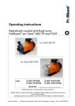
Operating Instructions
Magnetically coupled centrifugal Pumps
Types 2 / 2U / 2D
made of PP und PVDF
SONDERMANN PUMPEN + FILTER GMBH & Co. KG, D-51149 KÖLN
Tel.: +49-2203-9394-0, Fax: +49-2203-9394-48, E-Mail: [email protected]
Operating Instructions
EG-Konformitätserklärung
EC Declaration of Conformity
Déclaration de Conformité CE
Hiermit erklären wir, dass die Bauart der SONDERMANN magnetisch gekuppelte
Kreiselpumpen 45 W - 7,5 kW in verschiedenen Werkstoffen und Ausführungen,
in der gelieferten Ausführung folgenden einschlägigen Bestimmungen entspricht:
We herewith confirm that the construction of SONDERMANN magnetically coupled
centrifugal pumps 45 W - 7,5 kW of different materials and versions corresponds to
the following EC-rules:
Nous confirmons que la construction des pompes centrifuges à accouplement magnétique
SONDERMANN, 45 W - 7,5 kW, de matériaux et versions différents est conforme aux
dispositions règlementaires suivantes:
(1) EG-Richtlinie Maschinen
98/37/EG
(2) EG-Niederspannungsrichtlinie
73/23/EWG
93/68/EWG (1. Änderung)
EC Machinery Directive
98/37/CE
EC Low Voltage Directive
73/23/EEC
93/68/EEC (1st Amendment)
Directive CE Machines
98/37/CE
Directive CE Bas Voltages
73/23/CEE
93/68/CEE (1ère Modification)
Köln, 01.09.2007
2
Operating Instructions
CONTENTS
1
2
3
4
5
General Information ........................................................................................... 5
1.1
Fields of application ....................................................................................................5
1.2
Technical data.............................................................................................................6
Safety .................................................................................................................. 7
2.1
Marking of safety instructions in this operating manual ..............................................7
2.2
Qualification and training of operating personnel........................................................8
2.3
Hazards in the event of non-compliance with safety instructions................................8
2.4
Working in compliance with safety regulations ...........................................................8
2.5
Safety instructions relevant for operating the pump ....................................................8
2.6
Safety instructions relevant for maintenance, inspection and assembly work ............9
2.7
Unauthorized alterations and production of spare parts .............................................9
2.8
Inadmissible modes of operation ................................................................................9
Transport and storage ....................................................................................... 9
3.1
Transport.....................................................................................................................9
3.2
Storage........................................................................................................................9
Functional characteristics and accessories .................................................... 9
4.1
General description .....................................................................................................9
4.2
Constructional design................................................................................................10
4.3
Accessories and optional equipment ........................................................................11
Mounting / Installation ..................................................................................... 11
5.1
Mounting ...................................................................................................................11
5.2 Hose- and pipe lines .................................................................................................12
5.2.1 Suction line................................................................................................................12
5.2.2 Discharge line............................................................................................................12
6
7
5.3
Electrical connection .................................................................................................13
5.4
Check sence of rotation ............................................................................................14
Operation .......................................................................................................... 14
6.1
Preparations for starting............................................................................................14
6.2
Starting the pump ......................................................................................................15
6.3
Operation ..................................................................................................................15
6.4
Sut-down procedure ..................................................................................................16
6.5
Waste disposal..........................................................................................................16
Service / Maintenance...................................................................................... 16
7.1
General information...................................................................................................16
7.2
Preventive maintenance............................................................................................16
3
Operating Instructions
7.3
Dismantling the pump head ......................................................................................17
8
Troubleshooting ............................................................................................... 19
9
Spare parts ....................................................................................................... 20
9.1
Exploded view ...........................................................................................................20
9.2
Spare parts list ..........................................................................................................21
10 Appendix........................................................................................................... 22
10.1 Dimensioned drawing and specifications of RM- Type 2 ..........................................22
10.2 Dimensioned drawing and specifications of RM- Type 2U........................................23
10.3 Dimensioned drawing and specifications of RM-Twin Pump 2D...............................24
10.4 Capacity Curves ........................................................................................................25
11 Labour protection and accident prevention .................................................. 26
12 Declaration of harmlessness .......................................................................... 27
4
Operating Instructions
1 General information
The pump may only be used in the range of applications authorized by the manufacturer. In
case of modified operating conditions, please consult your pump's supplier and / or the
manufacturer.
1.1 Fields of application:
•
•
•
•
Pumping low-viscosity liquids resembling water.
Pumping of acids, bases and others.
Pumping of gaseous fluids.
Any use other than the authorized one as well as any conversion of the pump is not
permitted.
CAUTION!
Make sure that the materials of which the pump is made, are resistant to the fluids
delivered.
NOTE!
Ask your pump's supplier or the manufacturer for the respective chemical resistance
list.
• If you deliver crystallising fluids, make sure that the fluid does not crystallise within the
pump. Should this happen, carefully rinse off all parts being in contact with the fluid once
the pump has been shut off.
NOTE!
Disassembly of the pump will cancel the right to all warranty claims!
Power ratings
The nameplate on the pump not only specifies its model type but also its operating data and
serial number. Please indicate all these data when inquiring about an issue, reordering parts
and especially when ordering spare parts. For further information, contact your pump's
supplier or the manufacturer.
5
Operating Instructions
1.2 Technical data:
(Performance charts see page 21)
Max. volume flow:
see name plate
Max. delivery head:
Supply voltage:
see name plate
PP, PVDF, stainless steel,
ceramics, FKM , EPDM or
FEP
see name plate
Motor power:
0,09 up to 0,25 kW
Rated current: A
Rotation speedl:
see name plate
clockwise, seen from the
pump towards the motor
900 min-1 - 3400 min-1
Protection class:
IP 55
Weight:
approx. 4,0 - 7,0 kg
Used Materials:
Sense of rotation:
Max. admissible temperature of fluid delivered:
PP
80°C
PVDF
95°C
Maximum system pressure at 20°C:
PP
2,5 bar
PVDF
3,5 bar
NOTE!
To find out the maximum admissible temperature of the fluid delivered, check out the
materials of which the pump is made and which are indicated on the nameplate or the
delivery note.
The letters written on the nameplate are to be read as follows:
PP
= glass-fibre reinforced
Polypropylene
PVDF = Polyvinylidene Fluoride
K
= Oxide Ceramics
G
= PTFE graphite
V
= gasket*)
K
= ceramic sleeve bearings
K
= ceramic starting ring of the pump housing
K
= ceramic centering shaft
*) materials available:
V = FKM (fluorinated rubber)
E = EPDM (Ethylene-Propylene
Terpolymer)
T = FEP (Fluorinated Ethylene
Propylene coated)
6
Operating Instructions
2 Safety
When installing, operating and maintaining the pump, the mounting and operating
instructions detailed in the following should be strictly observed. Hence it is absolutely
necessary that prior to assembling and starting the pump, the responsible installation
personnel and/or users carefully read these operating instructions. Make sure that they are
always available wherever the pump is used.
Not only the safety instructions detailed in this Safety chapter are to be observed but also the
specific safety instructions provided in the following chapters.
2.1 Marking of safety instructions in this operating manual
Safety instructions given in this manual and non-compliance with which could be injurious to
human beings, are identified by the general:
safety sign
acc. to German DIN 4844-W standard
Warnings of electricity are identified by the specific:
safety sign
acc. to German DIN 4844-W standard
Safety instructions non-compliance with which would give rise to malfunctions of the
equipment are identified by:
CAUTION!
Signs and labels affixed to the equipment such as:
y arrows indicating the sense of rotation,
y symbols indicating fluid connections,
y warnings to protect the pump from dry-running,
must be strictly observed and always kept legible.
7
Operating Instructions
2.2 Qualification and training of operating personnel
All personnel responsible for operation, maintenance, inspection and assembly of the pump
must be adequately qualified.
Scope of responsibility and supervision of the personnel must be exactly defined by the plant
operator. If staff members do not have the necessary knowledge, they should be trained and
instructed accordingly. If necessary, the pump manufacturer or supplier will hold this training
on behalf of the plant operator. The operator should also make sure that all operating
instructions are fully understood by all personnel.
2.3 Hazards in the event of non-compliance with safety instructions
Non-compliance with safety instructions may produce a risk to personal life and health as
well as to the environment and the pump and may result in a loss of any right to claim
damages.
Non-compliance may involve risks such as
y failure of important functions of the pump and/or the installation;
y failure of specified procedures of service and maintenance;
y exposure of persons to electrical, mechanical, magnetic and chemical hazards;
y endangering of the environment because of hazardous substances leaking.
2.4 Working in compliance with safety regulations
When operating the pump, make sure to observe the safety instructions contained in this
manual as well as the relevant national accident prevention regulations and any other service
and safety instructions issued by the plant operator.
2.5 Safety instructions relevant for operating the pump
y If hot or cold machine components create any risk, they must be guarded against
accidental contact.
y Guards for moving parts must not be removed from the equipment during operation.
y Hazardous (i. e. toxic, hot) fluids must be drained off to prevent any risk to persons or the
environment. Statutory regulations are to be complied with in any case.
y Any hazard resulting from electricity should be ruled out completely. (For details see the
German VDE specifications and the bye-laws of your local power supply utilities, for
example.)
8
Operating Instructions
2.6 Safety instructions relevant for maintenance, inspection and assembly
work
It shall be the plant operator´s responsibility to ensure that all maintenance, inspection and
assembly work is performed by authorized and qualified personnel who have adequately
familiarized themselves with the subject matter by studying this manual in detail.
Any work on the equipment shall only be performed when it is at a standstill. Make sure to
strictly follow the procedure for shutting down the equipment prescribed in this manual.
Pumps and pump units that deliver hazardous fluids must be decontaminated after use.
On completion of work all safety and protective guards must be re-installed and be fully
operational again.
Prior to restarting the pump, make sure to follow the instructions detailed in the Starting
chapter below.
2.7 Unauthorized alterations and production of spare parts
The user is not allowed to subject the pump to any modification unless agreed upon with the
manufacturer. It is in the interest of your safety to use genuine spare parts and accessories
authorized by the manufacturer. Use of other parts may exempt the manufacturer from any
liability resulting thereof.
2.8 Inadmissible modes of operation
Die Betriebssicherheit der gelieferten Maschine ist nur bei bestimmungs-gemäßer
Verwendung entsprechend Abschnitt 1 „Allgemeines“ der Betriebsanleitung gewährleistet.
Die im Datenblatt angegebenen Grenzwerte dürfen auf keinen Fall überschritten werden.
3 Transport and storage
3.1 Transport
Das Gerät wird vom Hersteller betriebsfertig ausgeliefert. Bei Transportschäden muss in
jedem Fall eine Tatbestandsaufnahme durch den Transporteur durchgeführt werden. Der
Transport des Gerätes muss stets fachgerecht erfolgen.
3.2 Storage
The pump has to be stored absolutely dry and be protected from any pollutants entering.
4 Functional characteristics and accessories
4.1 General description
Magnetically coupled centrifugal pumps of type RM are non-self-priming centrifugal pumps.
They operate in horizontal position and are made of plastic in monobloc design. A magnetic
9
Operating Instructions
coupling connects the pump to the motor and transmits the power of the motor to the
impeller.
The type 2U is equipped with a non-ventilated motor and is insensitive to vapour.
The type 2D is equipped with a non-ventilated (0.25 kW) motor with two shaft ends. A pump
head of size 8/60 is mounted to each side of the motor.
You may use this pump as a twin pump with one driving motor to double is delivery rate to 2
x 80 l/min. or as a twin pump in series connection (two-stage) to increase discharge
pressure. Maximum delivery head then is 16 m WC.
4.2 Constructional design
Housing, impeller, impeller magnet and rear casing are made of plastic. Standard pumps are
equipped with centering shafts and bearings made of oxide ceramic. The rear casing
hermetically seals the fluid from the ambient atmosphere. Because of magnetic power
transmission, there is no need to mechanically seal the shaft. So, in contrast to mechanically
or gland sealed pumps, leakages through worn shaft sealings are definitely ruled out.
This pump is magnetically coupled. So when handling permanent-magnet components
during repair or maintenance work you are exposed to magnetic forces which might
influence pacemakers, for example.
, Keep your distance.
The pump housing parts are sealed by static O-rings. The impeller of the pump is a radialflow wheel. Depending on the fluid delivered, each component of the pump is available in
various materials.
NOTE!
The materials used for the pump are specified on its nameplate or the delivery note.
Choice of materials:
depends of type, see nameplate
Pump housing and
rear casing, impeller
and impeller magnet
coating
Centering shaft
Sleeve bearings
Starting rings
Static O-ring seals
PP
PVDF
oxide ceramic
oxide ceramic
PTFE - Graphite
oxide ceramic
FKM, EPDM, FEP
(FKM and FEP
coated)
10
Operating Instructions
4.3 Accessories and optional equipment
Accessory components including hose connections, pilotherms, motor circuit-breakers and
flow monitors, are available on request.
5 Mounting and installation
The pump should be installed at a place that allows easy access at any time. Make sure to
keep to the following limit values:
Ambient temperature
-10 °C bis +40 °C
Humidity of the air max. 95% relative
humidity, noncondensing
NOTE!
In case of higher ambient temperatures, please contact your pump's supplier or the
manufacturer.
5.1 Mounting
The pump is usually mounted in horizontal position, vertical position only upon request.
This pump is not self-priming and therefore requires a feed line.
Feed line from a container above the pump:
11
Operating Instructions
5.2 Hose and pipe lines
Make sure that the cross-sections of the pipelines fit the suction and discharge ports. All
suction and discharge lines to the pump housing should be free of tensile stress. The weight
of the hose and pipe lines must not rest on the housing.
CAUTION!
Do not install any quick-acting stop
valves into the pipelines, since
pressure jerks will damage the pump
housing.
5.2.1 Suction line
y The suction line should be a tube or hose which will not deform by the resulting partial
vacuum or by high temperatures.
y The suction line should be as short as possible. Make sure to mount it so that there will be
no gas accumulation.
y When dimensioning pipelines, fittings etc., make sure to keep the flow resistances as low
as possible.
y Flow velocity within the fitted suction line should not exceed the limit of 1m/s.
y For easy installation and removal of the pump, a shut-off valve (but no diaphragm valve)
should be built into the suction line.
CAUTION!
Do not use the shut-off valve built into the suction line to adjust the delivery rate.
5.2.2 Discharge line
y Standard flow velocity within the discharge line is 3m/s.
y To adjust the flow rate, we recommend installing a control element to the discharge line.
5.3 Electrical connection
All electrical connections to the pump should be performed by experts only.
12
Operating Instructions
y All electrical connections and installations of additional protection devices should be
performed by experts only and in accordance with the instructions of your local power
supplier and/or the Association of German Electrotechnical Engineers VDE.
y Make sure that the power supply has been cut off for at least 5 minutes before you start
working on the terminal box of the pump.
The electrical connections had to be done according to the following schematic
Connection scheme single-phase:
Connection scheme three-phase:
y Check out whether the power supply available corresponds to the data given on the
nameplate.
y The motor must be equipped with a motor circuit-breaker or a pilotherm to protect it from
overloading.
NOTE
Motor protection devices are
available with the pump's manufacturer.
13
Operating Instructions
5.4 Check sense of rotation
CAUTION!
Do not check the sense of rotation
before the pump is filled with fluid.
y Fill the pump housing and the suction line with water or the fluid to be delivered.
y Check the sense of rotation of the motor by switching it on and off in immediate
succession. The sense of rotation must be in accordance with the arrow figuring on the
pump.
Slip a soft material, such as a paper strip, into the slits of the motor skirt to determine the
sense of rotation.
y Mind the sense of rotation indicated by an arrow on the pump and verify it after
installation.
y The motor has to be protected from overload by a motor-protection-switch or a thermo
sensor.
NOTE!
Motor protection device are available by the suppplier!
6 Operation
6.1 Preparations for starting
Always wear protective clothing!
y Fill the pump housing and the suction line with water or the fluid to be delivered.
CAUTION!
Avoid any dry-running of the pump!
14
Operating Instructions
NOTE!
We recommend installing dry-running
protection devices such as flow
monitors, contact manometers,
differential pressure switches or level
controllers.
y Tighten all screwed connections.
y Entirely open all valves of the suction line.
6.2 Starting the pump
y Switch on the motor
y Check the sense of rotation.
y Adjust the operating point by slowly opening the shut-off valve of the discharge line. If
there is no shut-off valve installed to the discharge line, the operating point is
automatically adjusted in accordance with the characteristic curve of the pump.
CAUTION!
Do not run the pump with the discharge
line closed for a longer period of time.
This may result in heating up the fluid
inside the pump housing and damaging
interior components of the pump.
CAUTION!
Always protect the pump from coarse
impurities and magnetisable metal
particles within the fluid delivered.
6.3 Operation
If the motor-circuit breaker switched off the pump motor, proceed as follows:
y Before switching on the motor again, check whether the impeller turns readily.
y Make sure that the suction line and the pump housing are filled with fluid.
y Switch on the motor.
15
Operating Instructions
If the pump delivers for a short period of time only and then stops pumping, the magnetic
coupling has been disengaged. Proceed as described in chapter 8, Troubleshooting, below.
6.4 Shut-down procedure
y Switch off the motor.
y Close all valves.
y In case some fluid remains within the pump, secure the shut-off valves to prevent an
accidental opening.
y
If the pump is not to be used for some time, carefully rinse it off with a clean and neutral
liquid. This is to prevent remaining fluid from depositing within the pump and the sleeve
bearings.
y
If the pump is shut down for repair or maintenance work, lock the driving unit so that it
cannot be switched on. Before dismantling the pump, close the suction and the
discharge lines and empty the pump under controlled conditions.
Secure all valves to prevent an accidental opening.
Wear protective clothing.
6.5 Waste disposal
This product as a whole as well as parts of it should be disposed of in an environmentally
safe way.
CAUTION!
Please comply with the respective
regulations that are currently in force at
your place (especially with regard to
electronic scrap).
7 Service and maintenance
7.1 General information
This pump is designed for continuous operation and does not require specific maintenance.
7.2 Preventive maintenance
y
Although bearings, centering shaft and starting rings are designed for continuous
operation, they should be periodically inspected for deposits. Disassembly of the
pump head
16
Operating Instructions
7.3
Dismantling the pump head
1. Remove the 6 srews (901.1) of the pump
housing (101)
2. Take off the suction flange (162) from the
pump housing (161). Pull out the impeller
magnet with impeller (230 + 847.1) and
the centering shaft (211).
Required tool: open-end or ring
spanner of size 10
3. Take off the thrust disc (314.1) of the
pump housing (161)
Tools: No tools required!
4. Exchange of bearings (310.1 + 310.2) at
impeller magnet and impeller (847.1 und 230)
Required tool: Centering shaft (211)!
a) Take off the tool of the impeller
magnet in front direction (plug-in
connection) and press the bearing
out.
Tool: Screwdriver
b) Press out the bearing of the impeller
magnet in rear direction.
Tool: Arbor
c)
Put together impeller and magnet
front direction (plug-in connection)
and press the bearing out.
d) Press in the new bearings with lever
press and arbor (centering shaft) good
centered.
17
Operating Instructions
CAUTION!
After having replaced the bearings and
before re-assembling the pump
outlet/impeller casing, check manually
if the impeller magnet (847.1) and
bearings (310) really rotate on the
centre shaft (211)!
To assemble the pump outlet/impeller
casing, repeat step 1 to 3 in reverse order.
CAUTION!
After re-assembling the pump head, the
impeller (230) and impeller magnet
(847.1) should be able to slide axially
on the centre shaft (211)!
• Any other repair than the replacement
of word parts should be done only by
an expert, since inappropriate
maintenance word usually results in
unnecessary costs.
• If the pump will not be in operation for a
longer period of time, it should be
cleaned carefully. Otherwise you risk
that residues remaining in the pump
may harden and jam the impeller, once
the pump is started again.
18
Operating Instructions
8 Troubleshooting
Malfunction
Pump does not work when
switched on
Magnetic clutch is
disengaged
Motor is overheating
Causes
Corrective action
No voltage
Test the voltage
Impurities in the pump
housing
Specific gravity and/or
viscosity of the fluid is too
high
Pump was switched off, then
switched on again before the
rotor stopped
Clogged ventilator cowl
Remove the impurities
Reduce the delivery rate; use
a stronger magnetic clutch
and a more powerful motor
The rotor should have
stopped before the pump can
be switched on again
Clean the ventilator and the
cowl
Reduce the delivery rate
Use a stronger motor
Gas accumulation in the lines Evacuate the lines
Motor is overloaded
Pump is working, but not
delivering
Too much flow noise
Pump is not sucking
Delivery rate too low
Delivery rate too high
Valve in suction / delivery line Open the valves
is closed
Cavitation
Increase the suction line
cross-section
Reduce the delivery rate
cool down the fluid
No fluid in the pump
Open the vane
Air in the system
Evacuate the system
Increase the suction and
Suction and delivery line
delivery line cross-sections
cross-sections are too small
(significant losses)
Valve is not entirely open
Entirely open the valve
Pump losses are less
Install a flow control valve in
significant than presumed
the delivery line
NOTE!
If the pump runs dry, the inner magnet usually bonds with the rear casing. Because of
the impeller rotation, the fluid remaining in the pump housing heats up and
evaporates. As the resulting frictional heat cannot be removed, the plastic material of
the casing plasticizes and bonds with the inner magnet by "friction bonding". So do
not run the pump with the discharge or the suction line closed for a longer period of
time. Once the pump has run dry, liquid will leak out of the bore hole of the lantern
between pump and motor. This means that the bonding of the interior parts with each
other has resulted in a leaky rear casing.
19
Operating Instructions
9 Spare Parts
9.2 Exploded view
Drawing No. PUMA.02.Z.395.000
20
Operating Instructions
9.2 Spare Parts List
Item
Qty.
Description
Item
Qty.
Description
001
1
„Hirschmann“ plug socket GDM 3009 554
6
Washer 6,4 DIN 125 A 2
113
1
Motor lantern type 2
689
1
Insulated paper
160
1
Cover for terminal box type 2
732
1
Condenser holder
161
1
Pump housing type 2 G 1¼"
744
1
Sealing
162
1
Suction flange type 2 G 1¼"
813
1
Motor housing type 2
211*
1
Centering shaft ceramic type 2
818
1
Rotor
230*
1
Impeller type 2
826
1
Cable connection Pg 9
310.1*
1
Bearing ceramic type 2
833.1
1
Terminal box without cover type 2 Pg 9/11
310.2*
1
Bearing ceramic type 2
833.2
1
Terminal box for „Hirschmann“ plug socket
314.1*
1
Thrust disc ceramic type 2
835
1
Terminal board type 2
314.2*
1
Thrust disc ceramic type 2
837
1
Condenser
320.1*
1
Ball bearing 6202 ZZ C 2
847.1
1
Impeller magnet type 2
320.2*
1
Ball bearing 6001 ZZ
847.2
1
Drive magnet type 2
400.1
1
Seal for terminal box type 2
892
1
Footplate type 2 (PP)
400.2
1
Seal for terminal box type 2
900.1
2
Cylinder head bolt M4x12, DIN 84
400.3
1
Seal for „Hirschmann“ plug socket
900.2
2
Hirschmann-Befestigungsschraube M 3 x 35
412.1*
1
O – Ring for Housing 90 x 2,5
900.3
4
Cylinder head bolt M4x45 DIN 931 A 2
412.2*
1
O - Ring 93 x 2
901.1
6
Hexagon screw M 6x45, DIN 931, A 2
412.3*
1
O - Ring for pressure joint 26 x 3,5
901.2
2
Hexagon screw 6 x 16 DIN 933, A 2
412.4*
1
O - Ring for suction joint 30 x 3
904.1
1
Thread pin M 5 DIN 916 45 H
550
2
Rectangle disc A 2
904.2
1
Cylinder head bolt
550.1
1
Spacer washer
914
4
Hexagon socket head bolt M 5 x 12, DIN 912 A 2
550.2
1
Spacer washer
950
1
Corrugated spring
* Parts of wear and tear
NOTE!
When ordering spare parts, please indicate the items of the required parts, the pump
type, the serial-no., motor output and the drawing no.
NOTE!
Item 689 is only required for motors with an output of 250 W.
Item 833.1 and 826 may be replaced at item 833.2, 400.3, 001 and 900.2.
Item 732 and 837 are only necessary in case of A.C. motors.
21
Operating Instructions
9 Appendix
9.1 Dimensioned drawing and specifications of RM- Type 2
22
Operating Instructions
9.2 Dimensioned drawing and specifications of RM- Type 2U
( non ventilated )
23
Operating Instructions
9.3 Dimensioned drawing and specifications of RM-Twin Pump 2D
24
Operating Instructions
9.4 Capacity curves
Messwerte ermittelt mit Wasser (20°C)
25
Betriebsanleitung
11 Labour protection and accident prevention
NOTE
In order to protect their employees and other people as well as the environment from harmful
influences and effects when handling hazardous substances, industrial and commercial
companies are obliged to comply with legal provisions referring to labour protection such as
the German Workplace Regulations (ArbStättV), Hazardous Substances Regulations
(GefStoffV) and regulations for the prevention of accidents, as well as environmental
regulations such as the German Waste Act (AbfG) and the Water Resources Law (WHG).
We therefore ask you to enclose a declaration of harmlessness with any pump or component
you send us for repair. With this form duly filled in and signed, you declare that the pump or
the component was cleaned and thorougly rinsed with neutral fluid before being shipped to
us. Notwithstanding this, we reserve the right to refuse acceptance of repair orders for any
other reason.
So SONDERMANN products and their components are neither serviced nor repaired unless
this declaration of harmlessness is enclosed (see page …….. below).
Pumps that have been operated with radioactive substances are not accepted at all.
In case that, although the pump was carefully emptied and cleaned, we have to take any
safety precautions, you have to give us the necessary information when sending the pump or
its component.
26
Operating Instructions
12 Declaration of harmlessness
The undersigned herewith declares that the following pump and its accessories are harmless
and asks you to service and/or repair it or them.
Type of the pump:
...................................................................................................................
...................................................................................................................
Serial number:
...................................................
Date of delivery:
...................................................
Kind of problem:
...................................................................................................................
...................................................................................................................
We herewith declare that
the pump was not used to deliver harmful or noxious substances;
□
it was used with the following fluids:
..................................................................................................................................
..................................................................................................................................
□
before being shipped, the pump was carefully emptied and cleaned inside and
out;
□
it is not necessary to take any special safety precautions;
□
you have to take the following safety precautions with regard to residual fluids and
waste disposal:
...................................................................................................................................
...................................................................................................................................
Date:
signature:
27
PUMPEN + FILTER GMBH & Co. KG
August-Horch-Str.4
D - 51149 Köln (Cologne - Germany)
Tel.: +49 (0) 2203/9394-0
Fax: +49 (0) 2203/9394-48
[email protected]
www.sondermann-pumpen.de
28
Copyright by SONDERMANN PUMPEN + FILTER GMBH & Co. KG • Technische Änderungen vorbehalten • SB BG2 BG2U BG2D 08/2009 E
SONDERMANN
Operating Instructions
Subject to technical modification
29