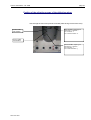
1
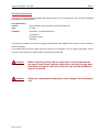
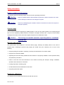
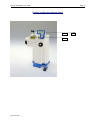
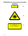
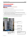
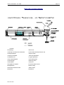
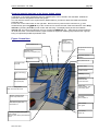
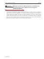
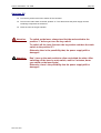
Laser
Operating Instructions
User´s Instructions DL 3000
page 1
CONTENTS
General information
3
Safety information
4
Danger symbols and information
4
Proper usage
4
Warranty and liabilitiy
4
Employer's obligations
5
Personnel's obligations
5
Laser safety officer
5
Protection of the eyes against laser radiation
6
Protection of the skin against laser radiation
7
Additional important Safety Information
8
Service activities
8
Position of laser warning signs
9
Basic laser and welding process
11
Technical description of the unit
12
Fuses and current distribution
12
Lamp pulse generator
13
Water - air heat exchanger
14
Laser beam source, focusing and observation optics
16
Beam path
17
Welding chamber
18
Main switch and key switch
20
The control box at eye level for the operator
20
Setting of the desired language on the display
20
Display and key pad at the control box
21
Call parameter settings from data base / set laser data anew
21
Program memory and pulse settings
21
Setting of individual parameters via the key pad at the control box
21
Save parameter settings in the data base
22
Delete parameter settings from the data base
22
Create texts and values in the memory and change them with the display key pad
22
Form pulses with the display key pad
23
Joystick
23
Store parameters temporarily and update them
24
User`s Instructions DL 3000
page 2
Reset the material data base to the factory default values
25
Configuration control box
25
Exhaust system
26
Installation
27
Ambient conditions for a safe operation of the laser
27
Transport and connection of the unit
27
Inert gas connection
28
Connection of the integrated cooling air nozzle
28
Operation
29
Switching On
29
Setting the stereo microscope
29
Welding
30
What to do if you receive a burn by laser radiation
31
Switching Off
32
Maintenance Information
33
Check lists
34
Testing the laser adjustment and the beam path
35
Adjustment of the laser welding spot to the crosshair in the microscope
36
Position of the adjusting screws on the deflecting mirror
37
Filling the tank with cooling water
38
Changing the particle filter in the tank of the heat exchanger
39
Changing the filter in the welding vapor exhaust system
39
Changing the lens protective glass
40
Changing the lamp
41
Possible failures, causes and fault clearance
42
Spare parts list
46
Technical Data
47
EU declaration of conformity
48
REV-26.09.2001
User`s Instructions DL 3000
page 3
General information
The laser you have purchased complies with the EC directives for such equipment and has been developed
especially for dental applications.
Unit identification
Product:
Laser welding unit (Nd:Yag laser wave length 1064 nm)
Type:
DL-3000
Company:
Dentaurum J.P.Winkelstroeter KG
Turnstraße 31
D-75228 Ispringen
Germany
The parts to be welded are manually arranged, positioned and laser welded in the welding chamber using the
stereo microscope.
The required inert gas and the laser pulse are switched on or activated via a two stage pedal switch. During
and after the processing the welding vapors is automatically extracted.
U
Caution:
Before switching on the unit you must have read and understood
the user's instructions! Switch on the device only after having done
this! Before using the unit for the first time, the relevant authorities
must be informed.
U
Caution:
Empty the cooling water tank before every change of the installation
site.
REV-26.09.2001
User`s Instructions DL 3000
page 4
Safety information
Danger symbols and information
The following symbols indicating danger are used in these operating instructions:
U
Warning:
Notes on possible threat to life and health of personnel. Failure to heed this can cause
serious damage to health and even dangerous injuries.
U
Caution:
Note on a possibly dangerous situation. Failure to heed this can cause minor injuries or
damage to property.
Correct usage
The DL 3000 is designed exclusively for welding metals. To use it for any other purpose or for anything beyond
this is to use it improperly. DENTAURUM is not liable for damages caused by this. Proper use also includes
heeding all information of this manual and regular inspections and maintenance work.
U
Caution:
Processing non-metallic materials, especially plastics, constitutes
improper use.
Warranty and Liability
Our general terms and conditions of sale and delivery apply. Warranty and liability claims in the event of
physical injury or damage to persons and property are invalid if they are caused by one or more of the
following:
• Improper putting into operation, operating, mounting and maintenance of the laser welder
• Improper use of the laser welder
• Operating the laser with safety facilities that are defective or improperly installed or with inoperative safety
and protective precautions
• Failure to heed the notes and information in this manual concerning the transport, storage, installation,
operation and maintenance of this laser
• Lacking supervision of wearing parts
• Unauthorized structural modifications to this laser
• Improperly performed repairs
Employer's obligations
The employer will only allow personnel to work with this unit who
REV-26.09.2001
User`s Instructions DL 3000
page 5
• are familiar with the basic regulations concerning safety at work and accident prevention and have been
instructed in the use of this unit.
• have read and understood the safety information and the warnings in this manual and have confirmed this
by their signature.
• have been instructed as to the dangerous effects of laser radiation in accordance with the valid regulations
about accident prevention for laser radiation (decree of the trade association VBG 93).
• Before using the unit for the first time, the relevant authorities must be informed.
Personnel's obligation
All personnel who work with the unit must undertake before starting to work to
• heed the basic regulations concerning safety at work.
• read and understand the safety information and the warnings and confirm them by their signature.
Laser safety officers
Using a class 4 laser, a competent laser safety officer must be appointed in writing by the employer. The
specialist should have training and experience in the field of laser radiation. The laser safety officer should
fully understand the safety procedures and equipment used. He is responsible for the safe operation and
safety measures of the unit.
The laser safety officer will receive appropriate training by the relevant trade associations or by
DENTAURUM.
Protection of the eyes against laser radiation
The unit is equipped to protect the eyes of the operator and other personnel around the unit.
1. Safety shutter
The safety shutter prevents generation of laser pulses or the unintended emission of laser radiation from
the laser source and is closed,
r
if the arm sleeves are open.
r
if the openings of the arm sleeves are not closed.
r
if the laser parameters are changed.
r
if there is no control voltage at the safety shutter.
REV-26.09.2001
User`s Instructions DL 3000
page 6
2. The laser pulse is only operational when
r
both arm sleeves are closed
r
and both forearms of the operator are in the welding chamber
r
and no laser parameters are set
r
and the charging of the energy reservoir has been finished
r
and the pedal switch has been pressed down to stage 2.
3. Other devices for eye protection
r
The unit is equipped with a large observation window out of laser protective glass for a safe direct
observation of the welding process.
r
The unit is equipped with an automatic glare protection within the optical path of the stereo
microscope that is activated during welding.
r
The complete laser beam path is optically sealed.
THE UNIT FULFILLS ALL CONDITIONS FOR TOTAL EYE PROTECTION.
This meets one part condition for a class I laser.
The unit does not fulfill the second part condition for a class I laser, skin protection against laser radiation.
REV-26.09.2001
User`s Instructions DL 3000
page 7
Protection of the skin against laser radiation
The unit has been developed for dental applications. Every workpiece is an individual part, the processes
cannot be automated. The dental workpiece must be held with the hands as a large number of various
materials with different measurements, appearances, surface compositions and fitting tolerances are
connected together in various combinations or have to be processed at their surfaces. At the moment
protective gloves against laser radiation technically cannot be realized and would hinder or even make
impossible to work on the very small parts. The same problem exists for the use of holders, tweezers etc.
Therefore this laser has to be classified as work equipment for the dental laboratory that bears the threat of
minor injuries.
Due to the design of the unit the area of danger is reduced to the hands and arms of the operator. In case of
false operation the tissue of the skin can slightly be burnt by laser influence. In case of severe burns the
operator should seek medical treatment.
U
Caution:
Invisible laser radiation!
You can avoid direct laser radiation to your hands:
r
Do not position your hands directly under the crosshair or in the laser beam!
r
Look through the stereo microscope and position the workpiece that the welding point appears
sharp within the crosshair!
r
Take care that the hands do not appear - if possible - in the field of view of the stereo microscope!
r
Keep your hands calm while releasing the laser pulse with the footpedal switch!
r
Always look through the stereo microscope and control the position of you hands and the position
of the workpiece!
U
Caution:
Scattered laser radiation
You can avoid scattered laser radiation to your hands:
Especially objects with shiny surfaces can scatter or deflect the laser radiation so that even in longer distances
of the welding point there is a certain local danger of burning!
r
If possible do not wear any jewelry on arms or fingers while working with laser radiation or do not
hold any shiny surfaces directly into the laser beam.
REV-26.09.2001
User`s Instructions DL 3000
page 8
Further important Safety Information, welding vapor exhauster
r The operating instructions must always be kept at the installation site.
r The device is a work equipment for welding dental metals and alloys with pulsed laser radiation. It
must not be used for other purposes.
r NEVER put inflammable or explosive substances in the welding chamber!
r During the welding VAPORS DANGEROUS TO HEALTH may be produced!
To keep the breathing air clean the trade association requests a corresponding welding vapor
exhauster for welding with the laser.
The exhauster integrated in the DL 3000 is only licensed for exhausting laser welding vapor. IT
MUST NOT BE USED FOR OTHER PURPOSES, e.g. for exhausting of
r
highly inflammable or explosive gases
r
fluids of any kind
r
organic substances (e.g. plastics)
The air outlet holes must always stay free. There must not be any damages at the suction hose and
it must be properly connected to the suction filter and the exhauster!
The welding vapor exhauster must only be operated with the original spare filter and never without
filter.
Maintenance activities
U
Attention: For all service and maintenance activities never work alone!
A second person, who should be at least familiar with the risks posed by laser radiation and high voltages,
should always be present during service and repair activities.
All activities on electrical or electronic components of the device must only be performed by authorized
qualified employees or by the Dentaurum service.
U Warning: Dangerous high voltage!
To ignite the flashbulb this laser is operated with high-voltage capacitors.
disconnected the device current-carrying components can still be live.
REV-26.09.2001
After having turned off or
User`s Instructions DL 3000
page 9
Position of the laser warning signs
2
1
REV-26.09.2001
3
User`s Instructions DL 3000
page 10
Laser warning signs
AVOID EXPOSURE
LASER RADIATION EMITTED
1
FROM THIS APERTURE
2
LASER RADIATION
AVOID EYE OR SKIN EXPOSURE TO
DIRECT OR SCATTERED RADIATION
CLASS 4 LASER PRODUCT
REV-26.09.2001
3
User`s Instructions DL 3000
page 11
Basics of the laser and the welding process
LASER = Light Amplification by Stimulated Emission of Radiation
It is a light amplification caused by stimulated emission of radiation. The light amplifier of the laser is a rod
shaped crystal of neodymium-doped yttrium aluminum garnet (Nd:YAG) stimulated by a light pulse from
an external rod shaped flash bulb. A suitable high-performance reflector guarantees a high efficiency and
coupling-in rate of the lamp light into the laser crystal.
In order to send out amplified and directive laser
light two mirrors are arranged outside the crystal that way that the light coming from the crystal is reflected
in itself and back to the crystal (resonator). One of the mirrors is semi-reflecting and releases a strongly
directive laser radiation from the resonator.
The wave length range of this radiation is strongly limited to
1064 nm. Due to the strong directional dependence and the narrow wave length range the extreme
concentration of the laser energy on the workpiece is possible (focusing via a suitable lens). This energy
concentration exceeds the concentration of usual light sources many times.
The laser pulse facilitates welding by heating the workpiece in the focal area beyond the melting
temperature and liquefying the materials that are to be connected. After a relatively short laser exposure
time (0,5 ms to 20 ms) the melted materials solidify again and are tightly connected together.
By the high and short time concentration of the laser energy to a limited volume heat is only produced
where it is needed. This feature makes the laser an excellent tool for the dental laboratory.
REV-26.09.2001
User`s Instructions DL 3000
page 12
Technical description of the device
Fuses and current distribution
U
Attention: Unplug the device before opening it.
The following modules are behind the left side door:
r The fuses F3 and F4 that are responsible for the cooling water pump for the remaining modules.
r A toroidal transformer for the power supply of the boards
r The supply board with further fuses responsible for various power supplies, the fan control of the heat
exchanger, the connections to the interlock sensors, the control of the magnetic valve for the gas supply,
the halogen lighting and for the control of the exhauster.
r The control board responsible for the control of the laser especially the lamp pulse generator, for the in- and
output of the laser parameters, the display control and the evaluation of the safety circuits.
r The automatic circuit breaker for the lamp pulse generator is behind the right side door.
Left side door open
Exhauster board
Control board
Supply board
Toroidal transformer for
alternating current supply
of the boards
REV-26.09.2001
Fuses F3 / F4 6, 3A-T
for all consumers, except the lamp
pulse generator
User`s Instructions DL 3000
page 13
Lamp pulse generator
A converter with sinus shape current input connectable to almost all supply voltages loads the capacitor
bank integrated in the lamp pulse generator. The stored energy is far higher than needed for one pulse.
Therefore the voltage decreases only slightly after every pulse. Shortly before the main pulse itself a small
ignition coil ignites and ionizes the lamp. This is the precondition for a reproducible and stable main
discharging.
During the main discharging two parallel high-power transistors connect the capacitor bank to the
flashbulb for an adjustable pulse duration (0.5 ms to 20 ms). The battery is automatically recharged after
the end of the pulse.
The loader is connected to the control via the optical fibers (LWL sender and receiver).
Signals from the control to the loader
Loader ON/OFF
Charging voltage (PWM signal)
Laser pulse ON/OFF
Signal from the loader to the controller
Charging voltage reached / charging finished
The following safety functions are integrated in the loader:
r
Forced rapid discharge of the capacitor bank after disconnecting the loader
r
Disconnecting in case of overvoltage
r
Disconnecting in case of overtemperature
From external via loader ON/OFF
r
Disconnecting in case of malfunction of the laser (interlock)
(see controller)
REV-26.09.2001
User`s Instructions DL 3000
page 14
Water - air heat exchanger
Each lamp flash produces dissipation heat in the laser head that must be dissipated to prevent
overheating of the device.
In the lower shelf of the device a dipping pump sucks water from a tank and pumps it through the laser
head past lamp and rod. There the water takes up the dissipation heat of the flashbulb. The heated water
is circulated up to a water-air heat exchanger. The heat exchanger fins are efficiently ventilated by a fan.
The water expels its heat to the air blown out upward.
The fan is continuously regulated depending on the temperature of the cooling water.
The cooled water flows back down through a particle filter into the tank.
The following safety functions are integrated in the tank (in the water reflux):
In
r
Flow sensor
r
Level switch
r
Overtemperature switch
case
of
one
Also refer to page 15
REV-26.09.2001
or
several
malfunctions
the
loader
is
disconnected
via
the
controller.
User`s Instructions DL 3000
page 15
Side view (right side door open)
Hose to connect the
external compressed or
cooling air
Hose to connect the
external inert gas
Automatic circuit breakers
F1/F2 for the lamp pulse
generator
Lamp pulse generator,
accessible from the back
Water tank for the cooling
water with pump and
particle/deionization filter
REV-26.09.2001
User`s Instructions DL 3000
page 16
Laser beam source, focusing and observation optics
A compact mechanically stable metal housing contains
r
the laser beam source with the mirrors and the laser head
r
the safety shutter to protect the eyes against unintended laser radiation
r
the telescope to adjust the focal spot diameter
The housing protects the optical components against welding dust, mostly avoids electromagnetic
disturbances to the outside and an unintended emission of laser radiation or scattered laser radiation.
A mechanical unit is flanged to the metal housing. It contains the following components:
A deflecting mirror to deflect the laser beam for 90° downward.
r The laser and observation lens to bundle the laser beam on the workpiece and to observe it via the
stereo microscope. The observation lens is equipped with a protective glass against welding dust
and metal splashes.
r The observation window with its protective glass to protect the environment against scattered laser
radiation.
r A stereo microscope to control the welding through the laser lens and via the deflecting mirror.
r An automatic glare protection for the eyes that closes the beam path to the stereo microscope during
the laser pulse.
Also refer to page 17
REV-26.09.2001
User`s Instructions DL 3000
page 17
Beam path (sectional drawing)
Legende
Rückspiegel
Rear mirror
Laserkopf mit Lampe und Laserstab
Laser head with lamp and laser rod
Auskoppelspiegel
Output coupler
Teleskop Verstellbar
Telescope adjustable
UV-Blendschutz
UV glare protection
Laser-Sicherheitsglas
Laser safety glass
Umlenkspiegel
Deflecting mirror
Laserobjektiv
Laser lens
Schutzglas für Objektiv
Protective glass for lens
Metallgehäuse
Metal housing
Sicherheits-Strahlverschluß
Safety shutter
Werkstück
Workpiece
REV-26.09.2001
User`s Instructions DL 3000
page 18
Welding chamber
For eye protection the complete laser path is shielded to the outside.
The workpiece is enclosed in a welding chamber that reduces the scattered laser radiation during welding
to a level that is save for the eyes. All openings for observation and positioning of the workpiece are
closed with permitted protective glasses against laser radiation or controlled by sensors.
The chamber has a
r
left and a right handflap through which the workpiece can be put into the chamber. At the handflaps there
are safety limit switches that only permit the release of laser pulses if both flaps are closed. Furthermore
there are sensors that only permit the release of laser pulses if both arms of the operator are within the
hand openings.
At the operators side of the housing is
r
a large-area laser protective window for direct pre-positioning of the workpieces
The following operating elements are mounted down at the rear side
r
Down left:
Rotary potentiometer to adjust the setting of the lighting
r
Up left:
Cooling air nozzle to cool the workpiece
r
Down below: Two joysticks to set the laser parameters from the working chamber.
The joysticks have the following functions:
Moving the
r
left joystick up/down:
Increase/reduce the focal diameter.
left joystick right/left:
Increase/reduce voltage.
right joystick up/down:
Increase/reduce frequency.
right joystick right/left:
Increase/reduce pulse duration.
Down below: Small joystick to select the parameter sets from the temporary memory
Moving the joystick downward: Select parameter set
Moving the joystick upward: Get parameter set from the temporary memory
r
Down right:
Rotary potentiometer to control the power of the exhauster
Left and right beside the laser lens are
r
one halogen spot each to illuminate the workpiece in the focal spot area
At the laser aperture
r
are mounted both inert gas nozzles with stopcock
REV-26.09.2001
User`s Instructions DL 3000
page 19
Figure: Welding chamber
Intake filter for
the exhauster
Cooling air nozzle
2.inert gas nozzle,
lockable
1. inert gas nozzle,
lockable
Upper position to
accept a selected
parameter set
Light barriers
to supervize the
(left) hand in the
welding chamber
Lower position to
indicate and
select parameter
sets
Brightness
controller
for the
halogen lamp
Power
controller
for the
exhauster
Left joystick
→Voltage (V)+
←Voltage (V) ↑ Focus ∅ +
↓ Focus ∅ -
REV-26.09.2001
Right joystick
→ Pulse duration (ms)+
← Pulse duration (ms) ↑ Frequency (Hz)+
↓ Frequency (Hz)-
User`s Instructions DL 3000
page 20
Main switch and key switch
r
Main switch
ON/OFF or EMERGENCY OFF switch for the
complete device. It switches on/off the water pump and enables
the power supply for the other components.
r
Key switch
Via the key switch of the control box the control and the loader are
switched on or off.
The control box at eye level of the operator
The following indication and operating elements are at the control box (see figure on page 24):
r
LED raster display
The display shows the reference input value for voltage, focal
diameter, pulse duration and frequency It shows a possible cause of
failure by plain text messages. Simultaneously the LED within the
CLEAR key comes on. The loader then is switched off.
r
LED ON
r LED
It shines green if the control has been activated with the key switch
*
shines red if the laser cannot pulse. This is the case if
The LED
the loader has not yet finished loading or is not ready or if the loader
has been cut off because of a malfunction (see interlock).
shines green if the laser pulse can be released with the
*
pedal switch.
The LED
r
Shutter Close key
The key closes the safety shutter, the LED shines red
r
Shutter Open key
This key enables the opening of the shutter: The LED flashes green.
If both hands are within the hand openings the shutter opens and the
laser can pulse. In this case the LED continuously shines green.
Also refer to page 25
Setting of the desired language on the display
The display at the control box can indicate the dental technical terms in five different languages. To
select the desired language plug in the mains plug and switch on the mains switch on the right side. Now
turn the key switch of the control box to „I“ and simultaneously press the MEM IN key of the control box
for several seconds. Confirm the selection menu language select by pressing the ↵ key. Now select the
desired language (German, English, French, Spanish or Italian) with the ↑/↓
↓ keys and confirm with the ↵
key. Then leave the selection menu by pressing the MEM OUT key. After that the system performs its
usual self check. The setting of the language is finished.
REV-26.09.2001
User`s Instructions DL 3000
page 21
Display and key pad at the control box
The parameters voltage, focal diameter, pulse duration and pulse frequency (V,∅,ms,Hz) can either be
set with the key pad of the display or via the joystick in the welding chamber.
If a set parameter exceeds the loading capacity of the loader the laser pulses with its maximum
frequency. The reduced frequency is indicated.
The following functions can only be set if no character flashes on the display and the parameters
(V,∅,ms,Hz) appear in the first line of the display (main menu).
1. Call parameter sets from data base / set laser data anew
The data base contains 8 material groups. A maximum of 16 entries (parameter sets) per material group
is possible for the various kinds of processing. Predefined parameter sets are assigned to the fist four
groups.
1. To call one material group press the MEM OUT key.
A list of material groups appears. To select the desired material group press the ↑/↓
↓ keys.
2. To call the parameter sets stored under the selected material group press the ↵ key.
The first parameter set of this group is indicated:
1. Line
2. Line
3. Line
4. Line
Name of the material group, parameter set no. [..]
Welding depths (comment)
The parameters (V, ∅, ms, Hz)
Pulse shaping S, pulse energy (J), pulse peak power (kW)
To select the desired parameter set press the ↑/↓
↓ keys.
3. To get the desired parameter set press the ↵ key.
Press the MEM OUT key to adjust the laser to the previously used parameter set or to cancel the
selection menu.
2. Program memory and pulse shaping
To make operation easier for the operator various welding programs have already been programmed in
the DL 3000. The pulse shaping can compensate differences depending on various alloys.
You will find a more detailed description of the user guide of these programs in the dental technical
instructions.
3. Setting of individual parameters via the key pad at the control box
1. Press the EDIT key to activate the parameter setting function.
2. One of the changeable parameters - voltage (V), focal diameter (∅), pulse duration (ms), pulse
frequency (Hz) or pulse shaping (S...) - flashes.
3. Select the desired parameter with the ↵ key and adjust the value of the desired parameter with the ↑/↓
↓
keys. With these settings you can start working immediately.
4. Press the EDIT key to switch off the parameter setting function.
REV-26.09.2001
User`s Instructions DL 3000
page 22
4. Save parameter sets in the data base
1. Set the parameter set that is to be stored.
2. Press the MEM IN key.
A list of material groups appears. Press the ↑/↓
↓ key to select the material group where the parameter
set is to be stored.
3. Press the ↵ key. the set parameters are added to the selected material group.
4. Press the MEM OUT key. the set parameters will not be accepted.
5. Delete parameter sets from the data base
1. To call one material group press the MEM OUT key.
A list of material groups appears. To select the desired material group press the ↑/↓
↓ keys.
2. To call the parameter sets stored under the selected material group
press the ↵ key.
The first parameter set of this group is indicated. Select the parameter set that is to be deleted with the
↑/↓
↓ keys.
3. First press the F key and then additionally the MEM-IN key.
The selected parameter set is deleted from the data base.
Press the MEM OUT key: the selected parameter set will not be deleted.
6. Create texts an values in the memory and change them with the display key pad
Instead of the names material A of material B you can enter any name for the material groups and
save them.
Moreover you can add individual comments to every stored parameter set, change stored parameter
sets and define them anew.
Change name of the material group:
1. To call the name of a material group that is to be changed press the MEM OUT key.
A list of material groups appears. To select the desired material group press the ↑/↓
↓ keys.
2. Press the EDIT key to activate the text editor.
The cursor flashes below the changeable character (= the text editor is active).
3. Set/indicate the desired text passage with the ↵ key and with the ↑/↓
↓ keys the desired character
at this place.
4. Press the EDIT key to close the text editor.
The flashing cursor disappears and the changed name of the material group is saved.
5. To get to the parameter sets stored under the material group press the ↵ key.
Enter/change comment to a stored parameter set anew and change parameter values in the stored
parameter set:
1. Press the MEM OUT key to select the material group where a comment is to be added to the
parameter set. A list of material groups appears.
To select the desired material group press the ↑/↓
↓ keys.
Press the ↵ key to indicate the first parameter set of this group. Select the desired parameter set
with the ↑/↓
↓ keys.
2. Press the EDIT key to activate the text editor.
The cursor flashes below the changeable character (= the text editor is active) in the second
line.
REV-26.09.2001
User`s Instructions DL 3000
page 23
3. Set/indicate the desired text passage with the ↵ key and with the ↑/↓
↓ keys the desired character
at this place.
4. Press the EDIT key anew to change the values in a parameter set in line 3 and 4.
5. The changeable parameter (V, ∅, ms, Hz, S) in line 3 or 4 flashes.
Select the desired parameter with the ↵ key and adjust the value of the desired parameter with
the ↑/↓
↓ keys.
6. Press the EDIT key to close the text editor.
The flashing cursor disappears and the changed data are saved.
7. Press the ↵ key to activate the new parameter set for the laser.
Press the MEM OUT key to get to the previously used parameter set.
7. Form pulses with the display key pad
This function determines the time behavior of the laser power during a pulse.
Altogether 4 different pulse shapes are programmed unchangeably (S1-S4).
The user can freely program the pulse shapes S5 to S8.
1. Press the SHAPE EDIT key.
A list of five pulse shapes appears. To select the desired pulse shape press the ↑/↓
↓ keys.
2. Indicate the desired pulse shape with the ↵ key.
The selected pulse shape is indicate with 10 horizontally equal time segments and with a
maximum of 8 height steps in every segment. A time segment corresponds to 1/10 of the set
pulse duration, a height step corresponds to about 1/8 of the determined laser pulse power.
If the voltage or the pulse duration is changed the shape of the pulse remains unchanged while
the complete pulse duration or height is shrinked or stretched.
3. Select the desired time segment with the ↵ key (horizontally, segment flashes) and set the
heigth of the selected segment with the ↑/↓
↓ keys.
4. Press the SHAPE EDIT key anew.
The changed pulse shape is stored.
„S_“ is the usual pulse without pulse shaping.
Joystick
Set parameters with the joystick
You can set the following parameters with the joysticks in the welding chamber:
-
left joystick →/←
←
left joystick ↑/↓
↓
right joystick→
→/←
←
right joystick ↑/↓
↓
REV-26.09.2001
voltage higher / lower
focal diameter bigger /smaller
pulse duration longer / shorter
frequency higher / lower
User`s Instructions DL 3000
page 24
Store parameter sets temporarily and update them
To facilitate fast access to the last used data or quickly switch from one parameter set to the other the control
is equipped with a temporary memory. You can save 4 parameter sets in the temporary memory. The contents
of the temporary memory is automatically deleted after having switched off the controller.
A bar indication is at the right lower edge of the display. The crossbars indicate the number of parameter sets
stored in the temporary memory. The dot in front of the crossbar indicates which parameter set of the
temporary memory is just indicated (see sketch).
If the temporary memory is empty no indication is displayed (status after switching on).
Example: Indication at the lower edge of the display:
Crossbar
1. parameter set in the temporary memory
2. parameter set in the temporary memory
3. parameter set in the temporary memory
Example: The display just shows the values of the 2. parameter set
Copy a parameter set to the temporary memory
Press the ↵ key once to manually copy the presently used parameter set to the temporary memory (e.g. to
quickly store a suitable parameter set for a new welding procedure). A bar indication appears at the right lower
edge of the display. The crossbars indicate the number of parameter sets stored in the temporary memory.
The dot in front of the crossbar indicates which parameter set of the temporary memory is just indicated.
To save a value from the material data base in the temporary memory first select the desired parameter set
with MEM OUT and the ↑/↓
↓ keys. Confirm the selection menu language select by pressing the ↵ key.
If there are already four sets in the temporary memory and an additional parameter set is to be added, the last
parameter set down below (see bar diagram) is deleted.
Select and accept a parameter set from the temporary memory
The memory is organized as a push-pop stack i.e. you can first access to the last stored data.
Fast access is possible with the small right joystick within the welding chamber.
If you push down the joystick (Data switch) you can select the three stored parameter sets. The dot in front of
the bar indication moves downward. Push the joystick upward (Data out) to accept one of the parameter sets.
Now the laser uses the values of this parameter set.
Delete a parameter set from the temporary memory
Push the small joystick downward (Data switch) to select a parameter set that is to be deleted.
Now press the F and MEM IN key simultaneously to delete the parameter set. If this is done with all parameter
sets the display shows the message recall stack empty and the temporary memory is empty.
REV-26.09.2001
User`s Instructions DL 3000
page 25
Reset the material data base to the factory default values
A maximum of 16 entries (parameter sets) per material group can be stored in the data base. Predefined
parameter sets are assigned to the fist four groups.
You can reset the device to the original factory default status if you want to delete self-made and useless
parameter sets.
For this turn on the main switch on the right side. Now turn the key switch of the control box to „I“ and
simultaneously press the MEM IN key of the control box for several seconds. Select the selection menu Entry
defaults by pressing the ↑/↓
↓ keys and confirm with the ↵ key. The display shortly shows the indication
defaults set. Then leave the selection menu by pressing the MEM OUT key. After that the system performs
its usual self check. The material memory again contains its original 8 material groups with the first 4 groups
being occupied with predefined parameter sets.
Figure: Control box
Number
of laser pulses
per second (Hz)
Pulse duration (ms)
Diameter of the
laseron the workpiece (mm)
Get parameter set from
the memory
Temporary memory
indication
Voltage (V)
Store parameter set
Pulsshape mode
S0 to S8
Increase values
Decrease values
Laser pulse energy
(J)
Enter key
Peak power of the
laser pulse (kW)
Function key
delete data sets
Access to service
Access or leaving of the
data- and name edit mode
Access or leaving of the
pulse shape edit mode
Main switch I :pump, fan,
Illumination on
Clear key: The LED shines yellow in
case of failure.
Press key after having eliminated the
failure
REV-26.09.2001
Ready LED:
Laser not ready : red
Laser ready: green
Key switch
ON: controller on
Open schutter
open: green
Close shutter
closed: red
User`s Instructions DL 3000
page 26
Exhauster
The device is equipped with a welding vapor exhauster with filter elements to remove the polluted welding
vapor from the welding chamber produced during the laser welding in order to keep the breathing air
clean.
Via a coarse filter in the welding chamber and a flexible hose the sucked polluted air reaches a combifilter
within the exhauster, consisting of a pre-filter and a suspended particle filter. This suspended particle filter
can separate finest particles (filter class EU 13 / K 2).
The sucking turbine transports the cleaned air through the lateral blow opening to the room.
The exhauster is started after every laser pulse and automatically switches off again after about 15 to 30 s
after the laser pulse.
REV-26.09.2001
User`s Instructions DL 3000
page 27
Installation
Ambient conditions for a safe operation of the laser
Ambient temperature for operation
10°C 30°C
Transport and storage temperature
5°C 45°C
Max. rel. humidity
70%
Max. height of installation site above sea level:
3.000 m
Transport and connection of the device
You can move the device without any problems on both rear wheels.
U
Attention:
Before any change of the installation site empty the cooling water
tank.
Installation
The device is automatically blocked if it stands on the two break blocks mounted below the feet.
The floor on the installation site must be even. Level out possible slight unevenness only with non-slip
material.
Suitable installation site:
The device has to be installed in a room as dust-free as possible, protected against direct sunlight.
It does not need much room. Place to stand: Width 600 mm times 815 mm depth plus place to sit.
To guarantee enough distance between the rear side of the device and the wall the rear side of the device
is equipped with spacers. This guarantees that the cooling air can be blown out to the back without any
problems and that the device cannot be overheated.
Electrical connection:
You can connect the device to a usual 230 V/50 HZ socket:
200 - 240V / 50 - 60 Hz / 16A
REV-26.09.2001
User`s Instructions DL 3000
page 28
Inert gas connection:
Please note the following:
U
r
Use argon 4.6 a inert gas (in case titan is processed argon 5.0 is recommended)
r
Use a gas cylinder with a volume of a maximum of 200 l.
r
Standing bottles have to be properly mounted to the walls with chains.
r
The flow regulation valve for argon should be set to a flow of 8 l/min.
r
The gas hose diameter is 6 mm.
r
The gas hose is directly plugged in at the laser housing beside the mains connection.
r
NEVER FORGET Close the valve of the gas cylinder after having finished working.
Attention:
Gas cylinders always must be properly secured for storing and
during operation.
Connection of the integrated cooling air nozzle:
Connect the transparent fabric hose beside the mains cable and the inert gas connection to the cleaned
compressed air. Max. pressure: 3 bar.
Fill cooling water into the tank of the heat exchanger
Filling the tank is described in the chapter notes on maintenance (page 38). During the first start-up
procedure you will be made familiar with the filling of the tank by our service.
REV-26.09.2001
User`s Instructions DL 3000
page 29
Operation
U
Attention:
Before switching on you must have read and understood the
user's instruction! Then you can switch on the device!
Switching On
r
Open the argon gas cylinder.
r
Turn the main switch to the right, position "I". After a lamp or cooling water exchange wait about 5
minutes until all air bubbles are removed from the cooling water circuit!
r
Turn the key switch to the right. Now the control is switched on.
r
After switching on the integrated micro processor performs a selftest to check important functions
of the device. The test is finished after about 1 minute.
r
After the selftest the LED ON shines green.
r
Press the Shutter open key. Now the device is ready for operation.
Setting of the stereo microscope:
r
Setting of the eye distance:
The eye distance is correct, if you can see with both eyes one single round image. Look into the
eyepieces and move both tubes with both hands together or apart.
r
Setting of the exit pupil:
The distance between the eye and the eyepiece is about 22 mm. You have got the correct distance
if you see the complete image area without shadings. Slowly move the eyes towards the eyepieces
r
Set the eye shells of the mircroscope:
If you do not wear goggles and wish to have close contact with the eyepieces: Hold the dioptric ring
and turn the eye shell anti-clockwise until it is released. Lift up the eye shell. Hold the dioptric ring
and tighten the eye shell clockwise. If you wear goggles move the eyeshell to the lowest position
r
Adjust the eyepieces to your individual visual acuity.
Set the dioptrics of both eyepiece to "0". Focus the crosshair in the right eyepiece by turning the
right dioptric ring. Position a flat test item (e.g. a sheet) on the small lift under the laser lens that it
appears sharp seen with the right eye. Focus the test item in the left eyepiece with the left dioptric
ring without moving the test item.
r
Every person who operates the laser only once has to adjust this setting. He should write
down his personal values (number of lines in + / - direction of both eyepieces). He has to set
these values again before working the next time with the laser. Only this way it is possible
that all persons can operate the laser with identical beam conditions using the same focal
settings.
REV-26.09.2001
User`s Instructions DL 3000
page 30
Welding
r
Open the handflaps to put the workpiece into the welding chamber
r
Close the handflaps
r
Both forearms must be positioned in the openings of the handflaps in order to release a laser pulse.
r
You should adopt a sitting position that allows you to work in a relaxed manner and comfortably
prop your forearms on both hand openings.
r
Position the nozzle for the inert gas supply that the workpiece or the area that is to be welded can
be covered with argon.
r
Adjust the laser parameters with both joysticks or at the controlbox (refer to page 21).
r
Put the parts that are to be welded with both hand together and position them by observing them
through the stereo microscope:
r
if you can see the workpiece exactly the vertical distance to the laser and observation lens is
correct.
r
if the crosshair is precisely on welding spot the horizontal position of the workpiece is correct
(the focal spot of the laser is identical with the crosshair)
r
Always pay attention that your hands do not appear directly under the crosshair of the stereo
microscope.
U
Attention: The laser beam can cause local burns!
r
Keep the positioned welding parts calm
r
If you touch the pedal switch the inert gas supply is released first (stage 1)
r
Press the pedal switch to position 2 to release a laser pulse. The view area in the stereo
microscope is shortly darkened during a laser pulse in order not to blind the eye by the plasma
torch created during the welding.
r
If more spots are to be welded keep the pedal switch pressed on stage 2. This way you can set
several welding points to a welded seam.
r
If no further spots are to be welded release the pedal switch
r
The inert gas supply remains active as long as you keep the pedal switch pressed on stage 1
r
If the welding is to be corrected or e.g. a seam is to be smoothed change the laser parameters with
the joysticks or the control keys
r
By positioning the black air nozzle you can cool a workpiece that has become too hot with
compressed air.
r
After the welding open the handflaps to remove the workpiece
REV-26.09.2001
User`s Instructions DL 3000
U
Attention:
page 31
Using other operation or adjusting elements as indicated in the
user's instruction or other methods can cause dangerous
exposure to radiation!
What to do if you receive a burn by laser radiation
If a laser pulse or scattered laser radiation unintentionally has burnt your fingers or hand, you might get a
slight local burn of the skin comparable to a burn by a hot soldering iron. Due to its wave length the
invisible infrared laser radiation only causes local thermal damages i.e. it acts like "normal thermal
radiation". Although a small burn of the skin by the laser pulse is not particularly critical, you should still
make sure that no infection results. If necessary you should treat the wound with a disinfectant.
Depending on the degree of the burn, you should undergo medical treatment.
REV-26.09.2001
User`s Instructions DL 3000
page 32
Switching Off
r
Turn the key switch to the left to switch off the controller.
r
Then turn the main switch to the left, position "0". This disconnects the power supply and the
remaining components of the device.
r
U
Close the valve of the gas cylinder!
Attention:
To switch on the laser, always turn first the main switch to the
position “I” before you turn the key switch!
To switch off the laser first turn the key switch and than the main
switch to the position”0”!
Otherwise there´s the possibility that, the power supply will be
damaged!
U
Attention:
REV-26.09.2001
Don`t turn on the main switch to often one behind the other. After
switching off the laser by main switch, wait for 5 minutes, bevor
you switch on the laser again!
Otherwise there´s the possibility that the power supply will be
damaged!
User`s Instructions DL 3000
page 33
Notes on Maintenance
U
Attention:
Only skilled persons are allowed to perform maintenance work at
the switched off laser!
If maintenance or service work is necessary at the switched on laser that requires the laser safety mechanisms
to be set out of operation it is just a laser class 4 device. All persons being in the same room must wear
protective goggles appropriate to the wave length of the laser. It is advisable to restrict the laser area by
protective walls or curtains that only persons within the laser area have to wear protective goggles.
U
U
Attention:
For all laser maintenance work the accident prevention regulations
have to be complied with, especially for Laser radiation and Safety rules for works
with voltage-carrying parts.
Attention:
REV-26.09.2001
Unplug the device before opening it.
User`s Instructions DL 3000
page 34
Check list 1
The following modules of the laser have to be checked every day before starting to work:
r
Is the viewing window scratched or polluted?
r
Do you have free view through the stereo microscope or is the lens protective glass polluted?
r
Are the light barriers at the hand openings working correct and can you hear the laser beam shutter
"switch".
r
Do the indication lamps for the laser shutter change from red to green without flickering?
r
Does the pedal switch work correctly?
Check list 2
The following checks are to be performed once a month:
r
Are the hand opening cuffs damaged or aren't they tight any more? Are the holding cuffs fixed
tightly?
r
Do the safety switches react after opening the side flaps? Are the safety switches mounted tightly?
Does the closing mechanism of the side flaps work correctly? Does the laser shutter close when
the side flaps are opened?
r
Does the key switch work properly and is it mounted correctly?
r
Does the main switch work properly and is it mounted correctly?
REV-26.09.2001
User`s Instructions DL 3000
page 35
Test of the laser adjustment and of the beam path
The laser adjustment should be checked once a week or if the welding results seem to be insufficient with the
usual laser settings.
r
Put the laser photo paper on the bottom of the welding chamber
r
Set the focal diameter to ∅2,0mm, the welding voltage to 290 V and the pulse duration 2 ms. Use
no pulse shaping (S-). Release a laser pulse.
r
Check the print on the photo paper:
The print should be round with a small roughened black edge.
The black photolayer should be removed uniformly. If the edge is frayed or if you can see small
black dots you have to change the protective glass for the lens.
If the spot is oval or disjointed and asymmetrical any objects are in the laser beam or the laser has
to be readjusted. Only the service is allowed to perform adjustment of the laser!
REV-26.09.2001
User`s Instructions DL 3000
page 36
Adjustment of the laser welding spot to the crosshair in the microscope
With the deflecting mirrors you can easily make congruent the laser beam with the crosshair in the
eyepiece of the microscope. Directly below the microscope within the welding chamber (beside the
yellow warning sign) a vertical black plate is mounted. The deflecting mirror is mounted with its
adjusting screws at this plate.
r
Put a small lift on the bottom of the welding chamber and put a writing pad with squared paper on
the lift. Focus the squares of the paper with the microscope.
r
Set a voltage of 290 V and a pulse duration of 2 ms at the device. Set the focal diameter to 0,2 +
r
r
mm and release a laser shot. Move the paper pad that the focal spot appears exactly in the
intersection of the squares on the paper.
r
You can incline the deflecting mirror directly from the welding chamber that the focal spot appears
exactly in the crosshair of the microscope (see drawing):
If you turn screw A to the right the welding point also moves to the right
If you turn screw B to the right the welding point moves upward
r
Release a laser shot with a new setting (voltage 360 V, pulse duration 5 ms, focal diameter
2.0 mm). Now you still must see the focal print in the center of the crosshair of the microscope. In
case of greater differences check the laser adjustment. Also the axis of the laser beam might be
misadjusted (please inform the service).
Also refer to page 37
REV-26.09.2001
User`s Instructions DL 3000
page 37
Position of the adjusting screws of the deflecting mirror
View through the front laser protective window (after having removed the cover)
DO NOT TURN
THIS SCREW!
Turn screw A for adjusting the
laser beam in x direction
turn clockwise: -x
turn counterclockwise: +x
DO NOT TURN
THIS SCREW!
Turn screw B for adjusting the
laser beam in y direction
turn clockwise: -y
turn counterclockwise: +y
REV-26.09.2001
User`s Instructions DL 3000
page 38
Filling the tank with cooling water
The tank of the heat exchanger must be always filled with sufficient deionized water (optimum water
level about 2 cm above the level meter / floater).
To fill the tank proceed as follows:
r
Switch off the device. Then unplug the power cord
r
Unscrew the hexagon screw of the right side door and open the door backward.
r
Loosen both screws of the supporting rail and remove it.
r
Unplug the connector of the water tank from the socket (connector the pump and the interlock
cable).
r
Lift out the gray cooling water tank and put it down.
r
Then open up the lid of the gray tank. Move both white bolts outward.
r
Fill the water tank with fresh deionized water up to about 4 cm below the edge.
r
Reconnect the lead-ins to the water tank.
r
Plug the mains plug and then turn the keyswitch to OFF, and the main switch to I.
r
Wait about 1 minute until the air has disappeared from the cooling system and the filter has sunk
down. If necessary refill destilled or deionized water up to 2 cm above the particle filter.
r
Switch off the device and unplug the power cord again.
r
Bolt the lid and put the tank back into the device. Take good care that the hoses are not bent.
r
Close the door again and lock it with the hexagon screw.
REV-26.09.2001
User`s Instructions DL 3000
page 39
Change of the particle filter in the tank of the heat exchanger
The particle filter must be changed about all 12 months independent of the working hours of the device.
At the same time the deionized water must be changed (about 5 to 7 l).
r
Switch off the device. Then unplug the power cord
r
Unscrew the hexagon screw of the right side door and open the door backward.
r
Drag out the connections to the pump and to the interlock cable.
r
Lift out the gray cooling water tank and put it down.
r
Then open up the lid of the gray tank. Move both white bolts outward.
r
Pour out the deionized water over one corner of the gray tank into a flat plastic vessel of about 10l
capacity.
r
Unscrew the inlet hose to the particle filter (white cylindrical vessel).
r
Put out the old filter and replace it by a new one.
r
Then connect the inlet hose
r
Fill the water tank again with fresh deionized water up to about 4 cm below the edge.
r
Plug the mains plug and then turn the keyswitch to OFF, and the main switch to I.
r
Wait about 2 minutes until the air has disappeared from the cooling system and the filter has sunk
down. If necessary refill destilled or deionized water up to 2 cm above the particle filter.
r
Switch off the device and unplug the power cord again.
r
Bolt the lid and put the tank back into the device. Take good care that the hoses are not bent.
r
Close the door again and lock it with the hexagon screw.
Change of the filter in the welding vapor exhauster
If the display indicates the message AIR FILTER the filter in the welding vapor exhauster must be
changed. In this case the filter is up to 80 % filled with particles.
You can delay the filter exchange if you increase the exhausting power with the rotary control in the
welding chamber (see also page 19).
r
Switch off the device at the mains switch and unplug the power cord.
r
Unscrew one hexagon screw on top and on the bottom of the front cover of the device. Pull of the
casing and disconnect the earth contact.
r
Unlock the filter at the excentric screw and lift it up. Lift up the filter when taking it out of the filter
chamber.
r
Put down the new filter inset on the filter chamber bottom, fold it in and fix it with the excentric
screw
REV-26.09.2001
User`s Instructions DL 3000
r
page 40
Connect the earth connection to the casing fix the casing again and srew it at the bottom and the
top.
U
Attention:
The particle filter contains residues of the welding vapor! Do not clean
and use the filter again but do expert recycle it.
Changing the lens protective glass
If the lens protective glass is polluted or defective you have to replace it by a new one.
r
Switch on the device with the mains switch.
r
Turn the hand flaps to the side
r
Grasp the lower side of the laser lens with one hand and turn the knurled holding ring to the left
r
Open the holding ring and take it out together with the protective glass
r
Remove the old protective glass and put the new one into the holding ring Now screw it together
with the new protective glass onto the lens.
REV-26.09.2001
User`s Instructions DL 3000
page 41
Lamp change
U
Attention:
Mechanical tension can be applied to the lamp. Wear safety
goggles when changing the lamp. Only our service or authorized
qualified employees are allowed to perform the lamp change.
r
Switch off the device at the mains switch and unplug the power cord.
r
Wait at least 3 minutes until all parts are free of any voltage.
r
Remove the upper cover behind the stereo microscope. For this loosen one hexagonal screw at the
left and the right and two at the rear side. Lift up the casing and disconnect the earth cable.
r
Completely unscrew both slotted head screws of the laser metal container. Slightly lift up the cover
and remove it to the back.
r
Loosen the four inner hexagon screws at the white lid of the laser head and slightly lift up the lid
until you can hear the cooling water flowing out.
r
Then take off the upper gold plated reflector bowl.
r
Completely loosen the hexagon screw at the clamps of the two lamp contacts and remove the
clamps.
r
Screw off the red and the black lamp cable at the brown isolating clamps.
r
Pull off the white pressure part and the O-ring from the cables.
r
Then carefully pull out the old lamp from the laser head. If the lamp is exploded carefully remove all
pieces of broken glass with tweezers.
r
Carefully insert the new lamp.
r
Replace the parts in opposite order and do not forget the O-rings!
r
Make sure that the clamps and the hexagon screws are fixed tightly. The screws of the white lid of
the laser head must be tightened regularly. The screws of the laser metal container should be
adjusted only slightly!
r
Plug in the power supply plug and only switch on the main switch.
r
Leave the water pump switched on about 3 minutes and wait until the air is removed from the
cooling water circuit!
r
Switch off the device and unplug the power cord.
r
After having switched off wait at least 3 minutes.
r
Completely unscrew both slotted head screws of the laser metal container and remove the lid
again.
REV-26.09.2001
User`s Instructions DL 3000
page 42
r
Check if the laser head and the water circuit are not leaky.
r
Put back the lid of the laser metal container again and slightly adjust the slotted head screws.
r
Remount the rear casing and connect the earth cable.
r
Plug in the mains plug and let the device run another two minutes until the water circuit is finally
deaerated.
r
Having turned the key switch the device is ready for operation.
Possible failures, causes and fault clearance
Error
Indication
possible cause
Clearance
C=customer
The following error appears after
having switched on the device
with the main switch.
Device does not react
no indication
Mains plug not connected
C, plug in mains plug
Pump does not run
Socket without current
C, check laboratory fusing
Exhauster does not run
Fuse F3/F4 blown
Service
Illumination remains dark
(see page 12)
The following error appears after
having switched on the device
with the key switch.
Display and indication without
no indication
Fuse F3/F4 blown
Service
function
24 V supply for controller defective
(see page 12)
Display and indication are on
e.g. "ROM TEST"
flat band plug for control board loose or
After selftest the display does not
not plugged
show the last set parameter set.
flat band plug for exhauster board
loose or not plugged
REV-26.09.2001
Service
User`s Instructions DL 3000
page 43
Error
Indication
possible cause
Clearance
Laser pulses, however error
AIR FILTER
air filter in the exhauster is filled up
C, change filter
message
Indication despite new air filter:
- control board of the exhauster is
Service
wrong calibrated
Laser does not pulse
LED ON
= green
* Loader not loaded up to the set
Service
voltage
LED
*
Interlock key
=
=
red
dark
* Fuse F1/F2 blown
Service
* Loader has performed forced outage
Service
as
C, key switch off and
- loading voltage too high
wait about 10 minutes
- thermal overloading because of
then switch on device with key
frequent switching on/off
LED ON
LED
*
Shutter open
switch
= green
* handflap(s) open
C, close handflaps
=
* hands are not deep enough in the
C, totally insert hands
red
= flashes
welding chamber.
green.
Laser does not pulse
LED ON
= green
* pedal switch pressed not deep
C, press until the stop
enough
LED
*
Shutter open
=
= green.
LED ON
LED
green
*
* Lamp defective
= green
* malfunction in the device,
=
loader is switched off
red
Service, change lamp
INTERLOCK key = yellow
and
* „HEX Interlock“
short time disturbance in the cooling
C, fill up cooling water over and
water circuit
above the white lid
as e.g. the level of the cooling water or
If cooling water level is all right
the flow is at the operate margin of the
change particle filter
sensors!
* „Temp Interlock“
Cooling water temperature > 50°C
Service, turn off key switch
let the exhauster and the pump
run about 10 minutes and switch
REV-26.09.2001
User`s Instructions DL 3000
page 44
on anew
* „ Flow Interlock“
REV-26.09.2001
Cooling water flow too low
Service
User`s Instructions DL 3000
Error
Indication
* „Level Interlock“
page 45
possible cause
Clearance
* kink in the hose
Check hose run
* Pump defective
Service
* filter blocked
Change particle filter
Cooling water level too low
C, fill up cooling water over and
above the white filter lid
Laser pulse energy too low at
* „Safety Shutter Interlock“
Safety shutter defective
Service
normal parameters
* protective glass polluted
C, change protective glass
* focal diameter too big
C, reduce focal diameter
* lamp aged
C, change lamp or increase
normal settings
voltage
Laser cannot be focused as
normal parameters
usual, beam diameter too big
* laser misadjusted
Service, adjust laser
* protective glass polluted
C, change protective glass
* eyepieces of the microscope not
C, focus the cross hair in the
correctly adjusted
* workpiece in wrong position
right eyepiece
C, position the height of the
workpiece that you can see it
clearly in the observation
microscope
Laser welding spot and crosshair
normal parameters
are not congruent
Laser welding spot is not round,
normal parameters
Bending mirror for the laser beam
C, adjust bending mirror with the
bending misadjusted
lowest right screw
* laser misadjusted
Service
* Shading by objects in the beam path
C, do not leave any cables in the
cornered or fringed
beam path after having changed
the lamp!
* laser rod holders leaky
Service
Water in the beam path
Laser welding spot uneven
normal parameters
* protective glass polluted broken
C, change protective glass
* protective glass polluted
C, change protective glass
spread
welding splashes on the glass surface
REV-26.09.2001
User`s Instructions DL 3000
page 46
* laser strongly misadjusted
Service
Error
Indication
possible cause
Clearance
Laser deeply drills into the
normal parameters
* focal diameter too small or power
C, increase focal diameter or
adjusted too high
decrease welding voltage.
* Alloy with too high fraction of
C, chose other alloy
workpiece, material splashes
low melting material
Despite low power laser melts a
hole in a thin plate
e.g. 15 210 to 2 V
thermal contact to the ground too low,
C, exactly adapt and press on
heat lag
plate shaped material that heat
can dissipate
Welding has cracks
A steel alloy with more than 0.3%
C, chose a steel alloy with less
Carbon has been used
than 0.3% carbon and
set pulse duration to >10 ms
and focal diameter >1 mm
Welding different materials:
* Melting point material A < material B
material A vaporizes,
C, increase part of the spot of
material B relative to material B
and select new parameters
material B melts
* material A has a higher laser beam
absorption than material B
Parts distort during welding
Welding point create tensile stress at
1. step fix together material with
the surface
several pulses
2. step alternately weld material
from two sides, but do not weld
to the depth from one side!
REV-26.09.2001
User`s Instructions DL 3000
Spare part list
Spare Parts .........................................................................................................Item No.
Particle filter in the water tank............................................................................................... 908-231-00
Filter inset in the welding vapor exhauster ........................................................................... 908-235-00
Prefilter for welding vapor exhauster ................................................................................... 908-235-00
Laser lamp ............................................................................................................................ 908-232-00
Protective glass for the lens.................................................................................................. 908-234-00
Acrylic glass protection for laser protective window 200 x 100 mm ..................................... 908-257-00
Halogen lamp with cold light reflector ................................................................................. 908-316-00
1 Cuff for the hand flap ........................................................................................................ 907-490-00
Service - Accessories
Laser protective goggles ...................................................................................................... 090-512-00
1 sheet in A4 format - detection paper for laser radiation
REV-26.09.2001
page 47
User`s Instructions DL 3000
page 48
Technical Data
Mechanical dimensions:
Width x height x depth
1240 x 550 x 815 mm
Weight
Approx. 125 kg
Electrical connection:
200 V - 240 V / 50 Hz - 60 Hz / 16 A
Laser:
Laser crystal
Nd:YAG
Wavelength
1.06 µm
max. average power
50W
Pulse energy
50mJ -55J
Pulse peak power
5kW
Pulse duration
0.5 - 20 ms
Pulse frequency
Single pulse
Welding spot diameter
Focal setting
max.10 Hz
0.2 - 2.0 mm
integrated, motor driven
Optical Viewing System
Stereo microscope with eyepieces for persons who wear goggles, 15-fold magnification, diameter of the
viewing area 16 mm.
Crosshair and indication of the most important laser parameters in the right eyepiece
Program memory:
Memory locations for 8 materials with 16 processing variants (parameter sets) each.
Exhauster:
integrated / with suspended particle filter class EU13/K2
Cooling air nozzle
integrated
Inert gas nozzle
2-fold / individually lockable and adjustable
Cooling
integrated / water-air heat exchanger
REV-26.09.2001
User`s Instructions DL 3000
page 49
EEC declaration of conformity
complies with the EU Directive 89/655 EEC for Work Equipment
We,
Dentaurum
J.P.Winkelstroeter KG
Turnstraße 31
75228 Ispringen
hereby declare that the work equipment named in the following complies with the relevant fundamental safety
and health standards of the EU directive because of its conception and construction as well as in the version
distributed by us.
This declaration looses its validity in case of any changes of the work equipment made without our consent.
Name:
Craftsmanship laser welding device for use within residential and industrial areas.
Type:
DL 3000
series no.:
106-001.01.00 - 106-099.12.01
Relevant EU directives:
EU Work Equipment Directive
EU Low Voltage Directive
EU Electromagnetic Compatibility Directive
(89/655 EEC)
(73/023 EEC)
(89/336 EEC)
Applied harmonized standards, especially:
EN 292-1
EN 60825
Safety Instructions for Laser Radiation
EN 60204
Electrical Appliance of Machinery
EN 207
Lasers Protective Filter
EN 50081-1 Limiting class B
Noise Emission (tightened version, for household
and light industrial area)
EN 50082-2
Jamming Immunity (tightened version, for industrial
area)
Applied national standards, especially:
VBG 93Accident Prevention Regulations for Laser Radiation
VBG 4
Accident Prevention Regulations for Electrical Equipment and Operational Fund
Date / Signature of manufacturer ...........................................................
Personal details to signatory
i.V. Dipl. Ing.(FH) K.Merkle
Productionmanager Mechanic III
REV-26.09.2001