1
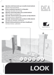
Leica M620 F18
Leica M620 CM18
Leica M620 CT18
User manual
10 714 371 – Version -
Thank you for purchasing a Leica surgical microscope system.
In developing our systems, we have placed great emphasis on
simple, self-explanatory operation. Nevertheless, we suggest
studying this user manual in detail in order to utilize all the
benefits of your new surgical microscope.
For valuable information about Leica Microsystems products
and services and the address of your nearest Leica representative, please visit our website
www.leica-microsystems.com
Thank you for choosing our products. We hope that you will
enjoy the quality and performance of your Leica Microsystems
surgical microscope.
Leica Microsystems (Schweiz) AG
Surgical Microscopy Business Unit
Leica M620 / Ref. 10 714 371 / Version -
Chapter overview
Introduction
3
Control
6
Preparation for operation
10
Use
25
Safety notes
31
Care and maintenance
40
Messages and warnings
44
Technical data
46
This manual covers the following systems:
Leica M620 F18
Leica M620 CM18
Leica M620 CT18
Leica M620 / Ref. 10 714 371 / Version -
1
Contents
Page
Page
Introduction
Design and function
Ceiling mounts
4
5
Controls
Control unit
Lamp housing
Tilt head/focus unit
Footswitch
User interface of the control panel
Stand
Remote control for Leica telescope mount
Optics carrier
Binocular tube, eyepiece, second observer tubes
6
6
6
7
7
8
8
9
9
Preparation for operation
Refitting the surgical microscope and balancing the
swing arm
Installing binocular tube, eyepiece and objective
Fitting adapters for accessories
Adjusting the second-observer tube
Fitting documentation accessories
Selecting documentation accessories
Setting the interpupillary distance and eyepoint
Adjusting the parfocality
Display/change footswitch type
Reversing + and – directions of the XY unit
Transporting the surgical microscope
Positioning the surgical microscope
at the operating table
Installing sterile components
Checking the function of the lamp
Adjusting the park position of Leica telescope mount
Adjusting the park position of Leica mini mount
10
11
14
15
17
18
19
19
20
20
21
Care and maintenance
Care instructions
Cleaning the control panel
Maintenance
Changing the fuse
Changing the bulb
Function check
Notes on reprocessing of resterilizable products
Instructions
40
40
40
41
41
41
42
42
Messages and warnings
General malfunctions
Microscope
Telescope
TV, photography
44
44
45
45
Technical data
Electrical data
Microscope
Stands
Ambient conditions
Standards fulfilled
Limitations of use
Dimensions
46
46
48
49
49
49
50
22
23
23
24
24
Use
Preparing the surgical microscope for use
Positioning the microscope
Adjusting the focus
Adjusting the magnification
Adjusting the illumination
Switching from main to spare illumination
Setting the illumination type and working distance
Operation of the control panel
Safety notes
Intended use
Information for the person responsible for
the instrument
User qualifications
Information for the user
Table 201 from EN 60601-1-2:2001
Table 202 from EN 60601-1-2:2001
Table 204 from EN 60601-1-2:2001
Table 206 from EN 60601-1-2:2001
Dangers of use
Signs and labels
2
24
25
25
25
26
27
27
28
31
31
31
31
32
33
34
35
36
37
Leica M620 / Ref. 10 714 371 / Version -
Introduction
Symbols in this user manual
User manual
In addition to instructions for use, this user
manual also provides important safety notes (see
the chapter entitled, "Safety notes").
Read the user manual carefully and thoroughly
before placing the product in operation.
The symbols used in this user manual have the following
meanings:
Warning
Product identification
Caution
The model and serial numbers of your product are located on
the identification label on the underside of the control unit, or
at the power input in the case of telescope mounts. Write this
data into your user manual and always refer to it when you
contact us or the service workshop regarding any questions
you may have.
Model:
Warning regarding use hazard or
noncompliant use that can lead to
serious injury or death.
Warning regarding use hazard or
noncompliant use that can lead to
minor injury, but significant article,
property or environmental damage.
Information provided to help the user
use the product technically correctly
and efficiently.
Serial No.:
➩
Leica M620 / Ref. 10 714 371 / Version -
Request for action; here, you are
requested to take action.
3
Introduction
Design and function
1 Swing arm
2 XY unit (optional)
3 Tilt head
4 Focus unit
5 Binocular tube
6 Eyepieces
7 Optics carrier
8 Objective
9 Control unit
10 Base
1
2
3
9
4
5
6
7
8
10
Leica M620 F18
4
Leica M620 / Ref. 10 714 371 / Version -
Introduction
Ceiling mounts
1 Leica M620 CM18
1
2 Leica M620 CT18
2
Leica M620 / Ref. 10 714 371 / Version -
5
Controls
Control unit
1 Power switch
2 Control panel
1
2
Lamp housing
1 Lamp replacement cover
2 Slide button for quick-change lamp mount
1
2
Tilt head/focus unit
Tilt head
1 Tilt head fine adjustment
Focus unit
2 XY unit reset button
3 Focus reset button
1
2
6
3
Leica M620 / Ref. 10 714 371 / Version -
Controls
Footswitch (standard configuration)
1
2
3
4
5
6
7
1
+
7
2
6
XY-adjustment
Microscope illumination darker
No function
Microscope illumination up/down
Zoom up/down
Focus bottom and top
Microscope illumination brighter
See page 29 for alternative footswitches and free
programming of footswitches.
5
4
3
See page 28 for using the control panel.
User interface of the control panel
Main menu
3
1
4
5
2
6
7
8
9
1
2
3
4
5
6
7
8
9
Illumination lighter/darker
Zoom up/down
Defective lamp warning
XY-reversal active
Speed menu
Reset All
XY reset
Focus reset
User selection 1–4
Speed menu
4
1
2
3
1
2
3
4
5
Zoom speed setting
Focus speed setting
XY speed setting
Back to main menu
Go to service area (password-protected)
5
Leica M620 / Ref. 10 714 371 / Version -
7
Controls
Stand
2
1
3
1
1
1
2
3
4
5
Articulation brakes
Rotary knob for balancing
Retaining hook
Footbrake release lever
Footbrake
4
5
Remote control for Leica telescope mount
1 Up/down motion button
1
8
Leica M620 / Ref. 10 714 371 / Version -
Controls
Optics carrier
1 Filter slot
2 Shutter knob for 6° illumination
3 Handles
1
2
3
Binocular tube, eyepiece, second observer tubes
1 Drive knob for eyebase adjustment
2 Diopter adjustment
3 Knurled ring for image correction
2
1
+5
-5
+5
-5
3
Leica M620 / Ref. 10 714 371 / Version -
9
Preparation for operation
Refitting the surgical microscope and
balancing the swing arm
Warning 1
Risk of injury through surgical microscope moving
down!
➩Never balance or re-equip the instrument over the
field of operation.
➩Balance out the swing arm each time after changing
accessories.
Locking the swing arm
➩ Position the swing arm approximately horizontally.
➩ Press retaining pin (2) and move the swing arm up and down
until the retaining pin snaps into place.
The swing arm is now locked.
1
Cleaning the optical accessories
➩ Inspect the cleanliness of the eyepieces and objective as
well as any photo or TV adapters as appropriate.
➩ Remove the dust and dirt.
Mounting accessories
➩ Equip the microscope with all the accessories for use.
2
2
+
–
3
10
Balancing the swing arm
➩ Hold the microscope.
➩ Pull the retaining pin (2).
The swing arm is now released.
➩ Test whether the microscope moves by itself (drifts).
Microscope drifts downwards:
➩ Turn the rotary knob (3) clockwise (+).
Microscope drifts upwards:
➩ Turn the rotary knob (3) anticlockwise (–).
Leica M620 / Ref. 10 714 371 / Version -
Preparation for operation
Installing the binocular tube, eyepiece
and objective
Installing the binocular tube
➩ Loosen clamping screw (1).
➩ Slide binocular tube into the
dovetail ring.
➩ Tighten the clamping screw.
1
A range of options enables the surgical microscope to be
matched to the requirements of the task in hand.
Warning 2
Risk of injury through falling binocular tube!
➩Tighten the clamping screw.
Binocular tube 10° – 50°, ultra low
Binocular tube 5°–25°
Binocular tube 10° – 50°, low
Inclined binocular tube
Binocular tube, 180° variable
Straight binocular tube
Binocular tube var. 30°–150°
Inclined binocular tube 45°
Option for use with assistant
attachment
(not standard configuration)
Leica M620 / Ref. 10 714 371 / Version -
11
Preparation for operation
Fitting the eyepiece
➩ Place eyepiece in position,
➩ Tighten rotary ring (1).
Eyepieces
Eyepiece 10x/21B, adjustable
Eyepiece 12.5x/17B, adjustable
1
Fitting objectives
Objectives screw onto the microscope with a right-hand thread.
Objectives
Objective WD = 175 mm APO
Objective WD = 200 mm APO
Objective f = 175 mm
Objective f = 200 mm
Objective f = 225 mm
Objective f = 250 mm
Objective f = 275 mm
Objective f = 300 mm
Fitting the objective protection glass
➩ Fit the objective protection glass holder (2) to the objective
and position it so that the marking (3) faces back.
➩ Hold the objective protection glass (5) in position and turn
slightly to the right.
The objective protection glass will snap into place and the markings (3) and (4) will match.
2
3
The objective protection glass is not autoclavable.
4
5
12
Leica M620 / Ref. 10 714 371 / Version -
Preparation for operation
Inserting additional filters
The Leica M620 features two slots for additional filters.
Temperature-resistant 32 mm dia. filters may be used.
For further information, please contact your Leica
representative.
➩ Remove cover (1) of the filter slots.
➩ Mount filter in filterholder with a tension ring.
1
➩ Insert the filterholder (2).
2
Leica M620 / Ref. 10 714 371 / Version -
13
Preparation for operation
Fitting adapters for accessories
Installing the beam splitter/stereo adapter
➩ Loosen clamping screw (1).
➩ Place beam splitter/stereo adapter into the dovetail ring.
➩ Tighten the clamping screw.
1
Beam splitter 50/50% observation,
alternatively beam splitter 70/30% observation
Stereo adapter for accessories
For the installation of accessories with M600 (dovetail ring)
mount under beam splitters with Leica M500 mount
(e.g. "Wild" laser filters).
1
Fitting the adapter
➩ Insert the adapter in the beam splitter.
➩ Tighten rotary ring (1).
Adapter for Zeiss accessories to Leica M500 mount
Adapter for Leica M600 accessories to Leica M500 mount
14
Leica M620 / Ref. 10 714 371 / Version -
Preparation for operation
Adjusting the second-observer tube
Install stereo attachment/second observer tube
➩ Insert the stereo attachment/second observer tube into the
beam splitter.
➩ Tighten rotary ring (1).
1
Stereo attachment for second observer
The dual stereo attachment can be attached to the left or right
on the beam splitter and turned as required.
Adjusting the second observer tube
➩ Turn the monocular second observer tube in the desired
direction.
➩ Adjust the diopter setting at the eyepiece.
➩ Correct the image with the knurled ring (2).
2
Adjusting the stereo attachment for second observer
➩ Turn the attachment for second observer in the desired
direction.
➩ Align the binocular tube horizontally.
➩ Adjust the diopter setting at the eyepiece.
➩ Correct the image with the knurled ring (2).
Leica M620 / Ref. 10 714 371 / Version -
15
Preparation for operation
Using the assistant's stereomicroscope
Warning 15
Risk of injury through falling surgical microscope!
➩Check the mounting of the assistant's stereomicroscope before every use.
The assistant's stereomicroscope can be used with the
following objectives:
- WD = 175 mm
- f = 200 mm
➩ Mount adapter with included screws (see manual of assistant's stereomicroscope).
➩ Focus assistant's image with sterile-operable focus drive (2).
Moving assistant's stereomicroscope to left/right:
➩ Remove sterile grips (3) with hub.
➩ Loosen clamping screw (1) and turn assistant's stereomicroscope.
➩ Tighten clamping screw (1).
➩ Turn hub and reattach sterile grips (3).
1
2
Depending on the accessories used, the turning range
may be partially or completely restricted.
3
16
Leica M620 / Ref. 10 714 371 / Version -
Preparation for operation
Fitting documentation accessories
Fitting the Leica 2D
➩See Leica 2D User Manual (10708979).
Fitting the photo/TV dual attachment
➩Fit dual attachment on the assistant side of the 0°-assistant’s
attachment or on the beam splitter.
➩Equip the video camera with the TV objective and insert into
the dual attachment.
➩Tighten clamping screw.
➩Equip the photo camera with the camera adapter. Screw the
photo objective to the camera adapter. Fit the camera to the
dual attachment.
➩Tighten the clamping screw.
➩Loosen the clamping screw and engage the video camera
until it latches in one of the 45° steps depending on the
available space.
➩Tighten clamping screw.
Adjust the parfocality of the zoom video adapter:
➩ Set to the maximum magnification.
➩ Place a flat test object with sharp contours under the
objective.
➩ Look through the eyepieces and focus the microscope.
➩ Set to the minimum magnification.
➩ Set the maximum magnification (f=100) on the zoom.
➩ Focus the monitor image on the zoom video adapter.
➩ Set the desired magnification at the zoom video adapter.
Fitting the phototube
➩ Fasten the phototube to the video port of the 0°-assistant’s
attachment or to the beam splitter.
Adjusting the magnification
Video camera (e.g. Leica 2D C-Mount)
Focusing knob
Clamping screw
The object image at the camera output is laterally
reversed!
➩ Secure the camera adapter to the SLR camera.
➩ Connect the f = 250 mm or f = 350 mm adapter to the camera
adapter.
➩ Secure the camera, complete with adapter, in the phototube.
Tighten the clamping screw.
Using the dial, the brightness of the video can be adjusted to 30%, 50% or 100%. One of these filters can be switched with the 8% filter provided. To do so, remove the
camera and change the filter in the TV output.
Camera
TV attachment / zoom video adapter
➩Fasten the TV attachment to the video port of the
O° assistant attachment or beam splitter.
➩Screw the adapter to the camera using the C-mount.
➩Insert the camera with the adapter into the TV attachment
and tighten the clamping screw.
90° click-stop (TV attachment only):
➩Loosen the clamping screw.
➩Latch the camera at one of the 90° steps in accordance with
the space available and tighten the clamping screw.
Camera adapter
Adapter
Clamping screw
Phototube
Beam splitter
Video camera (e.g. Leica 2D C-Mount)
C-mount adapter
Clamping screw
TV attachment
Beam splitter
Leica M620 / Ref. 10 714 371 / Version -
17
Preparation for operation
Selecting documentation accessories
Zoom video adapter
TV
attachment
PhotoTV dual
attachment
35mm
55mm
60mm
TV
attachment
70mm
PhotoTV dual
attachment
Zoom video
Adapter
TV
attachment
85mm
100mm
107mm
1/4 “
1/3 “
1/2 “
2/3 “
1“
Photo/TV dual attachment
250 mm
350 mm
35 mm
Digital
Photo
Camera
Field of view
Monitor/image
18
Leica M620 / Ref. 10 714 371 / Version -
Preparation for operation
Setting the interpupillary distance and
eyepoint
The interpupillary distance and preferred degree of contact
with the eyepieces vary from user to user.
Prepare the microscope for surgery using a user table.
Adjusting the interpupillary distance
➩ Set the eyelenses of the eyepieces to "0" or select the
required diopter value.
➩ Set the magnification changer to 10.
➩ Look into the eyepieces and adjust the tubes with the setting
wheel or by hand (in the case of binocular tubes without a
setting wheel) until a circular field of view is visible.
Interpupillary distance scale
75
65
55
Setting wheel
Adjusting the parfocality
Rotary ring for adjusting
the diopters
Adjusting the dioptric settings
The dioptrics are to be set exactly separately for both eyes;
only then does the sharpness remain constant within the entire
zoom range = parfocal.
1. Prepare the microscope
➩ Switch on the microscope at the control unit and place a flat
test object such as a piece of paper beneath the objective.
➩ Set to the maximum brightness.
➩ Set to the minimum magnification.
➩ Displace the microscope so that the test object is visible in
the center of the field of view and reasonably sharp.
2. Focus on the test object
➩ Set to the maximum magnification.
➩ Focus the microscope.
➩ Set to the minimum magnification.
3. Adjust the diopter setting
➩ Adjust the diopter setting for each eye in turn, so that the
image is seen in sharp focus.
➩ Set to the maximum magnification.
➩ Refocus the microscope.
➩ Set to the minimum magnification.
➩ Inspect the diopter settings, readjusting them if necessary
so that both images are sharp.
4. Checking parfocality
➩ Zoom through the whole range, observing the test object.
The image sharpness must remain constant at all magnifications. If it does not, then repeat points 2 to 4 of this procedure.
Leica M620 / Ref. 10 714 371 / Version -
19
Preparation for operation
Display/change footswitch type
See "Changing settings for footswitch", page 29.
Reversing + and – directions of the XY unit
-Y
+Y
+X
-X
-X
+X
-Y
The "XY-Reverse" function must be assigned to the
footswitch (see "Changing settings for footswitch",
page 29).
➩ Use the "XY-Reverse" button (1) on the footswitch to reverse
the + and – directions of the XY unit to – and +.
The "XY-reverse active" icon (2) on the control panel will light up.
+Y
1
1
2
20
Leica M620 / Ref. 10 714 371 / Version -
Preparation for operation
Transporting the surgical microscope
(floor stand only)
1
Caution 3
Swing arm can move in an uncontrolled manner!
➩ When transporting the surgical microscope, always
return it to the transport position.
Transport position
Locking the swing arm:
➩ Position the swing arm approximately horizontally.
➩ Press retaining pin (2) and move the swing arm up and down
until the retaining pin snaps into place.
The swing arm is now locked.
➩ Release the articulation brakes (2), fold the swing arm.
➩ Move the surgical microscope into transport position and
tighten the articulation brakes.
2
2
2
Caution 4
Feet in lightweight shoes could become trapped
beneath the casing of the base.
➩ Always push the instrument to displace it;
never pull it.
3
Transport the surgical microscope and secure it in its setup
position
➩ Pull the power plug from the socket and wrap the power
cable around the handle.
➩ Hang the footswitch on the handle.
➩ Release the footbrakes by depressing the foot lever (4).
➩ Push the surgical microscope to its new location by the
handle (3).
➩ Set the footbrakes at the new location.
4
Caution 5
Surgical microscope can move without warning!
➩ Always lock the footbrake when you are not moving
the system.
Leica M620 / Ref. 10 714 371 / Version -
21
Preparation for operation
Positioning the surgical microscope at the
operating table
Warning 6
Risk of death from electrical shock!
➩ The surgical microscope may be connected to a
grounded socket only.
➩ Using the handle, transport the surgical microscope to the
operating table and position it as needed for the operation.
➩ Set footbrake.
➩ Plug the power cable (3) into the socket and secure it with
cable ties (2).
➩ Connect the earthing potential in the socket (1) of the control
unit.
➩ Connect the footswitch in the socket (4) of the control unit.
1
2
4
3
Leica telescope mount option
1
Warning 8
Risk of injury through surgical microscope moving
down!
➩ Never position the surgical microscope over the
patient while moving it downward.
➩ Observe the surgical microscope while moving it
downward to prevent collisions.
Caution 9
Danger of collision!
The surgical microscope can collide with surrounding
components, the ceiling or lamps.
➩ Check the danger area before moving the swing arm.
➩ Carefully move the ceiling mount upwards, and
observe ceiling and lamps.
Move telescopic arm to the desired height:
➩ Activate push-button (1).
raise telescope arm
lower telescope arm
Under permanent-load conditions, the telescope may
not be operated for more than 1 minute in a 10 minute
period.
After 2 minutes of continuous operation the built-in
temperature switch turns the motor of the Leica telescope mount off.
22
Leica M620 / Ref. 10 714 371 / Version -
Preparation for operation
1
1
2
1
➩ Adjust the tilt of the footswitch. Set the adjustable support as
required.
➩ Inspect all connections and ensure that all accessories are
seated firmly.
➩ Release the articulation brakes and set them to a light resistance.
Make the joint easier to move:
➩ Release the articulation brake (1).
Make the joint more difficult to move:
➩ Tighten the articulation brake (1).
➩ Pull the retaining pin (2).
➩ Unfold the swing arm.
➩ Check the weight setting of the swing arm by raising and
lowering the microscope, correct as required; see page 10.
Caution 9
Risk of infection!
➩ Leave sufficient space around the stand to prevent
contact with non-sterile components.
Standard components:
• 1 handle, large black (tilt head)
• 2 handles, transparent
• 2 drive knobs
Installing sterile components
The handles are steam- and gas-sterilizable.
➩ Sterilize the handles and drive knobs.
➩ Attach the sterile drive knobs on binocular tube and drive
knob to block ambient illumination.
➩ Attach sterile handles to optics carrier and tilt head.
Checking the function of the lamp
➩ Actuate the power switch of the microscope.
The main lamp will light up.
➩ Move the slide button for the quick-change lamp mount (3) to
the other side.
The auxiliary lamp will light up.
➩ Move the slide button for the quick-change lamp back to the
main lamp.
The slide button for the quick-change lamp mount must
be slid fully against its stop, otherwise the lamp will not
light.
3
Leica M620 / Ref. 10 714 371 / Version -
23
Preparation for operation
Adjusting the park position of Leica telescope mount
Caution 8
Danger of collision!
The surgical microscope can collide with surrounding
components, the ceiling or lamps.
➩Check the danger area before moving the swing arm.
➩Carefully move the ceiling mount upwards, and
observe ceiling and lamps.
1
➩ Swing the microscope aside.
➩ Remove sterile components.
➩ Switch off the power switch.
➩ Move swing arm to uppermost position.
➩ Tighten all articulation brakes.
➩ Press "raise lift arm" button (1).
The Leica telescope mount will move upward.
Adjusting the park position of Leica mini mount
Caution 10
Danger of collision!
The surgical microscope can collide with surrounding
components.
➩Check the danger area before moving the swing arm.
➩ Swing the microscope aside.
➩ Remove sterile components.
➩ Switch off the power switch.
➩ Move swing arm to uppermost position.
➩ Swing the instrument out of working range.
➩ Tighten articulation brakes.
Preparing the surgical microscope for use
➩ Switch on the power switch (2).
The XY unit will move to its middle position.
The LED (page 25, position 2) lights up when the middle position
has been reached.
The focus will travel to its home position (1/3 up, 2/3 down) at
maximum speed. The LED (3) is lit when the focus reset position
has been reached.
2
24
Basic setting:
When switching the Leica M620 on with the power switch, the
zoom will travel to the same position it was in when the instrument was turned off. The intensity of the lamps and drive
speeds will revert to the programmed values of the last user.
Leica M620 / Ref. 10 714 371 / Version -
Use
Positioning the microscope
2
3
Adjusting the mid position:
➩ Press "reset XY unit" (4) button.
The XY unit will move to its middle position.
LED (2) is lit when the mid position has been reached.
Coarse positioning
➩ Hold both handles (6) to position the microscope.
1
4
5
Fine positioning
➩ Actuate the XY unit via the footswitch (7).
➩ Set the speed of the XY unit on the control panel
(see page 17).
6
Tilt fine adjustment:
➩ Use the tilt head fine adjustment (1) to set the tilt of the
microscope precisely.
+
-
9
7
Auto Reset
8
The "auto reset" function can be disabled in the service
area of the control panel.
➩ Hold both handles and move the microscope to its uppermost position.
All drives will move to their reset positions and the illumination
will go out. When the microscope is returned to its working
position, the illumination will switch on at the configured starting value.
Adjusting the focus
(in accordance with factory settings)
Adjusting the magnification
Basic setting:
➩ Press "reset focus" button (5). The focus will travel to its
home position (1/3 up, 2/3 down) at maximum speed.
LED (3) is lit when the focus reset position has been reached.
Adjusting the focus:
➩ Press programmed button (8) or (9) on footswitch.
➩ Set the speed on the control panel (see page 27).
➩ Set the magnification on the control panel (see page 26).
Leica M620 / Ref. 10 714 371 / Version -
25
Use
Adjusting the illumination
(in accordance with factory settings)
1
3
2
Warning 6
Intense light can injure the eyes!
Light which is too intense can damage the retina, therefore:
➩ Select short exposure times and low intensities.
Warning 12
Excessive illumination levels can injure the retina.
➩To protect the patient,
- minimize exposure times
- use lower intensity settings
- use protective filters (GG420 integrated)
We recommend setting the minimal required light intensity for the
operation. Infants, aphakic patients who have not had their lenses replaced by artificial lenses with UV protection, small children, and persons with eye diseases are at higher risk. The risk is
also elevated if the person to be treated has been exposed to illumination from the same or a similar ophthalmological instrument
with an intense visible light source within the previous 24 hours.
This applies especially to patients that have been examined via
retinal photography.
The decision with regard to the light intensity to be used must
be made on a case-by-case basis. In any event, the surgeon
must evaluate the risks and benefits of the used light intensity.
Damage may occur despite all efforts to minimize the risk of
retinal injury by surgical microscopes. Photochemical retina
damage is a possible complication arising from the necessity to
use intense light to make eye structures visible during difficult
ophthalmological processes.
Switching the microscope illumination on and off
Use button (3) to switch the microscope illumination on and off.
➩ Adjust the intensity of the main illuminator on the control
panel (see page 26) or with the footswitch.
(1) higher,
(2) lower intensity.
The intensity level is displayed in percent on the control
panel.
26
Leica M620 / Ref. 10 714 371 / Version -
Use
Switching from main to spare illumination
The defective lamp warning icon in the main menu of the control panel flashes whenever a lamp is defective.
Warning 11
Failure of the illumination can be dangerous for the
patient!
➩ If the main lighting fails, switch to the emergency
lighting immediately.
Replace the defective illumination at the next opportunity.
Never begin an operation with only one functioning
illumination unit.
The slide button for the quick-change lamp mount must
be slid fully against its stop, otherwise the lamp will not
light.
➩ Move the slide button for the quick-change lamp mount (4) to
the other side.
The auxiliary lamp will light up.
4
Setting the illumination type and working
distance
➩ Set the approximate working distance by raising or lowering
the microscope with the handles (2).
➩ Turn the rotary knob (1) clockwise.
Ambient illumination/6° illumination is hidden.
Red reflex illumination/0° red reflex illumination is retained.
The 6° illumination can be adjusted with the rotary button (1) to
optimize red reflex and contrast. The 0° light will remain permanently.
1
2
Leica M620 / Ref. 10 714 371 / Version -
27
Use
Operation of the control panel
The main menu will appear on the control panel when the
Leica M620 is switched on. The following settings can be
configured there:
5
1
2
3
4
Calling up the settings of the surgeon
Use buttons 1–4 (7) to call up the custom settings (starting
values, speeds, footswitch assignments) of the operating
surgeon.
➩ In "User", press button 1–4 (7).
The values stored under the button will be applied.
To program the buttons, see "Custom settings for the operating
surgeon".
6
7
Adjusting brightness and magnification
Brightness and zoom can be adjusted continuously.
➩ Press arrow keys "+" or "–" in "Light" (1).
The brightness will change as required.
➩ Press arrow keys "+" or "–" in "Zoom" (2).
The magnification will change as required.
Restoring settings
If settings (brightness, magnification) are changed, the original
values can be restored.
➩ In "Reset", press the "All" button (3).
The values stored under the appropriate button will be applied.
Going to reset positions
➩ In "Reset", press the "XY" button (4).
The XY unit will move to its middle position.
➩ In "Reset", press the "F" button (5).
The focus will travel to its home position (1/3 up, 2/3 down).
Adjusting the working speeds for zoom, focus and XY unit
➩ In the main menu, press the "Speed" arrow button (5).
The "Speed" menu will open.
➩ In the "Speed" menu, use the "+" or "–" arrow keys to select
the desired working speed.
8
To save the values, see page 27.
➩ Press "Main" arrow button (8).
The main menu will reappear.
9
Accessing the service area
The service area is password-protected. Please contact your Leica service representative.
➩ In the "Speed" menu, press the "Service" field (9) and enter
the password.
The service area will now appear.
28
Leica M620 / Ref. 10 714 371 / Version -
Use
3
1
4
2
6
5
Setting the focus, zoom and XY unit speeds
➩ In the "PROG-Start Values" menu, press the "Speed" arrow
button (3).
The "PROG-Speed" menu will open.
➩ Use the "+" or "–" arrow buttons to set the desired speeds for
zoom (7), focus (8) and XY movements (9).
➩ Press button "Save" (11).
The settings will be stored for the selected button.
or
➩ Press button "back" (10).
The configuration process will be canceled and the
"PROG-Start Values" menu will reappear.
The field (12) indicates the user (1–4) for whom the settings are
currently being configured.
10
7
8
9
11
12
16
13
15
14
Custom settings for the operating surgeon
➩ In the main menu under "User", press for at least 3 seconds
the button 1–4 under which the settings should be saved.
The "PROG-Start Values" menu will appear.
➩ Adjust the starting values for brightness (1) and magnification (2) as required.
➩ Press button "Save" (6).
The settings will be stored for the selected button.
or
➩ Press button "Back" (5).
The configuration process will be canceled and the main menu
will reappear.
17
18
12
Changing the footswitch settings
➩ In the "PROG-Start Values" menu, press the "Footswitch" button (4).
The "PROG-Footswitch" menu will open.
➩ Select the connected footswitch at the footswitch icon (13)
using the "+" or "–" arrow keys.
➩ Press the button to be programmed (14) on the footswitch
icon (❍ becomes ●).
Select the desired function in the middle block (15) with the "+"
or "–" arrow keys and confirm your choice with "OK" (17).
➩ When all of the footswitch buttons are programmed, press
"Save" (18).
The settings are now saved.
or
➩ Press button "back" (16).
The configuration process will be canceled and the
"PROG-Start Values" menu will reappear.
Leica M620 / Ref. 10 714 371 / Version -
29
Use
Copying settings to another user
The settings stored for one surgeon may be copied to another.
➩ In the main menu, press the button (1) with the settings to be
copied for at least three seconds
(e.g. "1").
The "PROG-Start Values" menu will appear.
➩ Press the desired target button (2) (e.g. "2").
➩ Press button "Save" (3).
The settings for button "1" now also apply to "2".
1
3
2
Setting Auto Reset
This function can be disabled in the service area.
Please contact your Leica service representative.
When the "Auto Reset" function is enabled, all drives move to
their reset positions and the illumination is turned off when the
surgical microscope is moved to its uppermost position.
When the microscope is returned to its working position, the
illumination will switch on at the configured starting value.
30
Leica M620 / Ref. 10 714 371 / Version -
Safety notes
Intended use
• The Leica surgical microscope is an optical instrument for
improving the visibility of objects through magnification and
illumination. It can be applied for observation and documentation and for human and veterinary medical treatment.
• The Leica surgical microscope may be used only in closed
rooms and must be placed on a solid floor or attached to a
strong ceiling.
• The Leica M620 surgical microscope is subject to special precautionary measures for electromagnetic compatibility. They
must be installed and put into operation in accordance with
the guidelines, manufacturer's declarations and recommended safety distances (Tables 201, 202, 204, and 206 from
EN 60601-1-2:2001).
• Portable and mobile as well as stationary RF communications
equipment can have a negative effect on the reliability of the
Leica M620 surgical microscope.
Information for the person responsible
for the instrument
➩Ensure that the surgical microscope is used only by persons
qualified to do so.
➩Ensure that this user manual is always available at the place
where the surgical microscope is in use.
➩Carry out regular inspections to make sure the personnel is
complying with safety requirements.
➩Brief the user thoroughly and explain the meaning of the
hazard signs and safety precautions.
➩Assign individual responsibilities for starting, operating and
servicing the Leica surgical microscope and monitor the
observance of these responsibilities.
➩Only use the surgical microscope if it is free of defects.
➩Inform your Leica representative or Leica Microsystems
(Schweiz) AG, BU SOM, 9435 Heerbrugg, Switzerland, immediately if you detect a product defect that could potentially
cause injury or harm.
➩If you use accessories made by third-party manufacturers
with the Leica surgical microscope, be sure that each such
manufacturer confirms the safety-engineering, harmless usability of the product and observe the product's user manual.
➩Modifications to or service on the surgical microscope may
be carried out only by technicians who are explicitly authorized by Leica to do so.
➩Only original Leica replacement parts may be used in servicing the product.
➩After maintenance or technical modifications, the device
must be readjusted in accordance with our technical specifications.
➩If the device is modified or maintenance has been performed
by unauthorized personnel, if the equipment is improperly
maintained (providing the maintenance was not performed by
us) or if the device has been operated improperly, Leica is
relieved of all liability.
➩The effect of the surgical microscope on other instruments
has been tested as specified in EN 60 601-1-2. The system has
passed the tests relating to emissions and immunity. Comply
with the usual precautionary and safety measures relating to
electromagnetic and other forms of radiation.
User qualifications
The Leica surgical microscope may only be used by physicians
and medical assistance personnel with appropriate qualifications who have been instructed in the use of the instrument. Specific training is not required.
Information for the user
➩Follow the instructions given in this manual.
➩Follow the directions provided by your employer regarding
work organization and safety.
Stability (floor stands only)
When moved in OP, the swing arm must be folded up and
locked and the brakes must be applied, otherwise the swing
arm may drift out of control and the stand could topple.
Hazards due to moveable parts
This section describes uses that, inadvertently, could lead to
hazardous situations.
• Add accessories and balance the stand before the operation,
and never over the field of operation.
• Do not put your fingers between the microscope and the
focusing drive; they could get crushed.
Floor stand:
• When displacing the stand, push it. Do not pull it. Feet in lightweight shoes could become trapped beneath the casing of
the base.
• The footbrakes must remain engaged throughout the
operation.
Electrical connections
The control unit may be opened only by a Leica-approved
service technician.
Accessories
Only the following accessories may be used with the Leica
M620 surgical microscope:
• The Leica accessories described in this user manual.
• Other accessories, provided that these have been expressly
approved by Leica as being technically safe in this context.
Leica M620 / Ref. 10 714 371 / Version -
31
Safety notes
Manufacturer's declaration of electromagnetic compatibility (EMC)
This "Guidance and manufacturer's declaration" document is based on EN 60601-1-2:2001.
Table 201 from EN 60601-1-2:2001
Guidance and manufacturer's declaration – electromagnetic emissions
The Leica M620 surgical microscope is intended for use in the electromagnetic environment specified below.
The customer or the user of the Leica M620 surgical microscope should assure that they are used in such an environment.
Emissions test
Compliance
RF – emissions group 1
according to CISPR 11
For its internal functions, the Leica M620 surgical microscope uses RF
energy only. Therefore, its RF emissions are very low and it is not likely
to cause any interference in nearby electronic equipment.
HF – emissions
according to CISPR 11
class A
Harmonic emissions
according to IEC 61000-3-2
Class A
Emission of
voltage fluctuations/
Flicker emissions according
to IEC 61000-3-3
complies
32
Electromagnetic environment – guidance
The Leica M620 surgical microscope is suitable for use in establishments other than domestic and those directly connected to the public
low voltage power supply network that supplies buildings used for
domestic purposes.
Leica M620 / Ref. 10 714 371 / Version -
Safety notes
Table 202 from EN 60601-1-2:2001
Guidance and manufacturer's declaration – electromagnetic immunity
The Leica M620 surgical microscope is intended for use in the electromagnetic environment specified below. The customer or the
user of the Leica M620 surgical microscope should assure that they are used in such an environment.
Immunity test
IEC 60601 test level
Compliance level
Electromagnetic environment – guidance
Electrostatic discharge
(ESD) according to
IEC 61000-4-2
± 6 KV
Contact discharge
± 6 KV
Contact discharge
± 8 KV air discharge
± 8 KV air discharge
Floors should be of wood, concrete or
ceramic tile. If floors are covered with
synthetic material, the relative humidity
should be at least 30%.
Electrical fast transient /
burst
according
to IEC 61000-4-4
± 2 KV for
power supply lines
± 2 KV for
power supply lines
± 1 KV for input
and output lines
± 1 KV for input
and output lines
Surges
according
to IEC 61000-4-5
± 1 KV
Differential mode
± 1 KV
Differential mode
± 2 KV
Common mode
± 2 KV
Common mode
<5% UT (>95%
dip in UT)
for 1/2 cycle
<5% UT (>95%
dip in UT)
for 1/2 cycle
40% UT (60%
dip in UT)
for 5 cycles
40% UT (60%
dip in UT)
for 5 cycles
70% UT (30%
dip in UT)
for 25 cycles
70% UT (30%
dip in UT)
for 25 cycles
< 5% UT (>95%
dip in UT)
for 5 seconds
< 5% UT (>95%
dip in UT)
for 5 seconds
Magnetic fields at power
frequency
(50/60 Hz) according to
IEC 61000-4-8
3 A/m
not applicable
Note:
UT is the a.c. mains voltage prior to application of the test level.
Voltage dips, short interruptions and voltage variations
on power supply lines
IEC 61000-4-11
Leica M620 / Ref. 10 714 371 / Version -
Mains power quality should be that
of a typical commercial or hospital
environment.
Mains power quality should be that
of a typical commercial or hospital
environment.
Mains power quality should be that of a
typical commercial or hospital environment. If the user of the Leica M620 surgical
microscope requires continued operation
during power mains interruptions, it is
recommended that the Leica M620 surgical
microscope be powered from an uninterruptible power supply or a battery.
33
Safety notes
Table 204 from EN 60601-1-2:2001
Guidance and manufacturer's declaration – electromagnetic immunity
The Leica M620 surgical microscope is intended for use in the electromagnetic environment specified below.
The customer or the user of the Leica M620 surgical microscope should assure that they are used in
such an environment.
Immunity test
IEC 60601 test level
Compliance level
Electromagnetic environment – guidance
Portable and mobile RF communications
should be used no closer to any part of the
Leica M620 surgical microscope, including
cables, than the recommended separation
distance calculated from the equation applicable to the frequency of the transmitter.
Recommended separation distance:
Conducted RF –
disturbance according to
IEC 61000-4-3
3V
150 kHz to 80 MHz
3V
Radiated HF –
disturbance according to
IEC 61000-4-3
IEC 61000-4-3
3 V/m
80 MHz to 2.5 GHz
3 V/m
eff
eff
d = 2.4 P
for 150 kHz to 80 MHz
d= 2.4 P
for 80 MHz to 2.5 GHz
Where P is the maximum output power rating
of the transmitter in watts and d is the
recommended separation distance in meters
(m). Field strengths from fixed RF transmitters,
as determined by an electromagnetic site
survey, should be less than the compliance
level in each frequency range. Interference
may occur in the vicinity of equipment marked with the following symbol:
Note 1:
At 80 MHz, the higher frequency range applies.
Note 2:
These guidelines may not apply in all situations. Electromagnetic propagation is affected by
absorption and reflection from structures, objects and people.
a Field strengths from fixed transmitters, such as base stations for radio (cellular/cordless) telephones and land mobile radios,
amateur radio, AM and FM broadcast and TV broadcast cannot be predicted theoretically with accuracy. To assess the electromagnetic environment due to fixed RF transmitters, an electromagnetic site survey should be considered. If the measured
field strength in the location in which the Leica M620 surgical microscope is used exceeds the applicable RF compliance level
above, the Leica M620 should be observed to verify normal operation. If abnormal performance is observed, additional measures may be necessary, such as reorienting or relocating the Leica M620.
b Over the frequency range 150 kHz to 80 MHz, field strengths should be less than 3 V/m.
34
Leica M620 / Ref. 10 714 371 / Version -
Safety notes
Table 206 from EN 60601-1-2:2001
Recommended separation distances between portable and mobile RF telecommunication devices and the Leica M620 surgical
microscope.
The Leica M620 surgical microscope is intended for use in an electromagnetic environment in which radiated RF disturbances
are controlled. The customer or user of the Leica M620 surgical microscope can help prevent electromagnetic interference by
maintaining a minimum distance between portable and mobile RF communication equipment (transmitters) and the Leica M620
as recommended below, according to the maximum output power of the communications equipment.
Separation distance according to frequency of transmitter in m
Rated maximum output
power of transmitter W
150 kHz to 2.5 GHz
d = 2.4 P in m
0,01
0.24
0,1
0.8
1
2.4
10
8.0
100
24.0
For transmitters rated at a maximum output power not listed above, the recommended separation distance d in meters (m)
can be estimated using the equation applicable to the frequency of the transmitter, where P is the maximum output power
rating of the transmitter in watts (W) according to the transmitter manufacturer.
Note 1:
These guidelines may not apply in all situations. Electromagnetic propagation is affected by
absorption and reflection from structures, objects and people.
Warning message:
Using accessories or cables other than those specified here or as approved by the manufacturer of the Leica M620 surgical
microscope may result in increased electromagnetic emissions or decreased interference resistance.
Warning message:
The Leica M620 surgical microscope may not be used in direct proximity of other devices. If it is necessary to operate them in the
vicinity of other instruments, the microscopes should be monitored to ensure that they function properly in this arrangement.
Leica M620 / Ref. 10 714 371 / Version -
35
Safety notes
Dangers of use
Warning 1
Risk of injury through surgical microscope moving
down!
➩Never balance or re-equip the instrument over the
field of operation.
➩Balance out the swing arm each time after changing
accessories.
Warning 2
Risk of injury through falling binocular tube!
➩Tighten the clamping screw.
Caution 3
Swing arm can move in an uncontrolled manner!
➩When transporting the surgical microscope, always
return it to the transport position.
Caution 4
Feet in lightweight shoes could become trapped
beneath the casing of the base.
➩Always push the instrument to displace it;
never pull it.
Caution 5
Surgical microscope can move without warning!
➩ Always lock the footbrake when you are not moving
the system.
Warning 6
Risk of death from electrical shock!
➩The surgical microscope may be connected to a grounded socket only.
Warning 7
Risk of injury through surgical microscope moving
down!
➩Never position the surgical microscope over the
patient while moving it downward.
➩Observe the surgical microscope while moving it
downward to prevent collisions.
Caution 8
Danger of collision!
The surgical microscope can collide with surrounding
components, the ceiling or lamps.
➩Check the danger area before moving the swing arm.
➩Carefully move the ceiling mount upwards, and
observe ceiling and lamps.
Caution 9
Risk of infection!
➩Leave sufficient space around the stand to prevent
contact with non-sterile components.
36
Caution 10
Danger of collision!
The surgical microscope can collide with surrounding
components.
➩Check the danger area before moving the swing arm.
Warning 11
Failure of the illumination can be dangerous for the
patient!
➩If the main lighting fails, switch to the emergency
lighting immediately.
Warning12
Excessive illumination levels can injure the retina.
➩To protect the patient,
- minimize exposure times
- use lower intensity settings
- use protective filters (GG420 integrated)
Caution 12
Damage to the control panel
➩Operate the control panel using your fingers only.
Never use hard, sharp or pointed objects made out of
wood, metal or plastic.
➩Never clean the control panel using cleaners that
contain abrasive substances. These substances can
scratch the surface and cause it to be become dull.
Warning 13
Risk of death from electrical shock!
➩Before replacing the fuse, unplug the power cable
from the power socket.
Caution 14
Risk of burns!
The lamp and its mount get very hot.
➩Check that the lamp and mount has cooled before you
remove the lamp.
Warning 15
Risk of injury through falling surgical microscope!
➩Check the mounting of the assistant's stereomicroscope before every use.
Warning
Risk of infection!
This antimicrobial coating is no substitute for the usual
cleaning and sterilization procedures according to
applicable regulations.
➩ Cleaning and sterilization must be performed according to applicable regulations.
Leica M620 / Ref. 10 714 371 / Version -
Safety notes
Signs and labels
Type 10448205
S/N XXXXXXXXX
Grounding reliability can only be achieved when EQUIPMENT is connected to
equivalent receptacle marked "Hospital only" or "Hospital Grade".
La fiabilité de la mise à la terre n'est assurée que si l'équipement est connecté
à une prise équivalente, marquée «Hôpital seulement» ou «Qualité hôpital».
Leica M620 / Ref. 10 714 371 / Version -
37
Safety notes
Danger sign for hot surface
38
Leica M620 / Ref. 10 714 371 / Version -
Safety notes
Only one of the two nameplates, depending on the supply voltage variant.
Leica Microsystems (Schweiz) AG
CH-9435 Heerbrugg
MODEL
LEICA M620 CM18
100V~/240V~50/60Hz
250VA
2xT6,3A/250V
Leica M620 / Ref. 10 714 371 / Version -
39
Care and maintenance
Care instructions
Cleaning the control panel
• Put a dust cover over the instrument during breaks in work.
• Keep accessories in a dust-free place when not in use.
• Remove dust with a pneumatic rubber pump and a soft
brush.
• Clean the objectives and eyepieces with special optics cleaning cloths and pure alcohol.
• Protect the surgical microscope from damp, vapors, acids,
alkalis, and corrosive substances.
Do not keep chemicals near the instrument.
• Protect the surgical microscope from improper handling.
Do not install other device sockets or unscrew optical
systems and mechanical parts unless explicitly instructed to
do so in this user manual.
• Protect the surgical microscope from oil and grease.
Never oil or grease the guide surfaces or mechanical parts.
• Remove coarse debris with a moistened disposable cloth.
• For disinfecting the surgical microscope, use compounds
from the surface disinfecting group based on the following
active ingredients:
aldehydes,
alcohols,
quaternary ammonia compounds.
Due to potential damage to the materials, never use
substances based on
halogen splitting compounds,
strong organic acids,
oxygen splitting compounds.
Follow the disinfectant manufacturer’s instructions.
It is recommended to conclude a service contract with
Leica Service.
Caution 12
Damage of the control panel
➩Operate the control panel using your fingers only.
Never use hard, sharp or pointed objects made out of
wood, metal or plastic.
➩Never clean the control panel using cleaners that
contain abrasive substances. These substances can
scratch the surface and cause it to be become dull.
➩Before cleaning the control panel, switch off your Leica M620
and disconnect it from the power supply.
➩Use a soft, lint-free cloth to clean the control panel.
➩Do not apply cleaning agent directly to the control panel;
rather, apply it to the cleaning cloth.
➩Use a commercially available glass/eyeglass cleaner or
plastic cleaner to clean the control panel.
➩Do not apply pressure to the control panel while cleaning it.
The control panel is resistant to most disinfectants
used in the medical field.
Maintenance
The Leica M620 surgical microscope is basically maintenancefree. To ensure that it always operates safely and reliably, we
recommend that you take the precaution of contacting the
responsible service organization.
Here you can arrange for periodic inspections and, if necessary, conclude a maintenance contract.
It is recommended to conclude a service contract with
Leica Service.
Use only original spare parts for servicing.
40
Leica M620 / Ref. 10 714 371 / Version -
Care and maintenance
Changing the fuse
Warning 13
Risk of death from electrical shock!
➩Before replacing the fuse, unplug the power cable
from the power socket.
1
➩The fuses are located in a fuse holder (1) in the instrument
power socket.
➩Use a screwdriver to push the fuse holder out before
removing it completely by hand.
➩Change the fuses.
➩Reinsert the fuse holder and press it fully home by hand.
Changing the bulb
Caution 14
Risk of burns!
The lamp and its mount get very hot.
➩ Check that the lamp and mount has cooled before you
remove the lamp.
Replace defective lamps immediately after an operation to ensure that a replacement lamp is available at
all times.
Use only genuine Leica replacement lamps.
2
3
Function check
➩ Open lamp replacement cover (2).
➩ Pull the halogen lamp and base (3) out of its holder.
➩ Insert the halogen lamp and base into the holder until it
clicks into place.
➩ Close lamp replacement cover (2).
Lamps
➩ Switch on the power switch.
Main lighting is lit.
➩ Switch to the auxiliary lighting.
The auxiliary lamp will light up.
➩ Switch back to the main lighting.
Footswitch
➩ Position the footswitch.
➩ Test all the functions with the footswitch.
Leica M620 / Ref. 10 714 371 / Version -
41
Care and maintenance
Notes on reprocessing of resterilizable
products
Products
Reusable products supplied by Leica Microsystems (Schweiz)
AG such as rotary knobs, objective protective glasses and
capping pieces.
Limitation of re-preparation:
Observe relevant local regulations pertaining to the re-preparation of medical products used in connection with verified or
suspected cases of Creutzfeldt-Jacob disease (CJD) or its variant (vCJD). As a rule, resterilizable products used with this patient group can be disposed of safely by incineration.
Occupational safety and health protection
Particular attention must be paid to the occupational safety and
health protection of the persons responsible for preparing
contaminated products. Current regulations of hospital hygiene
and prevention of infection must be observed in the preparation, cleaning and disinfection of the products.
Limitation of reprocessing
Frequent reprocessing has little effects on these products.
The end of the product life cycle is usually determined by
wear and year and damage through use.
Instructions
Antimicrobial coating
The essential parts of the instruments feature an antimicrobial
coating designed to prevent the spread of microorganisms.
Warning 16
Risk of infection!
This antimicrobial coating is no substitute for the
usual cleaning and sterilization procedures according
to applicable regulations.
➩The instrument must be cleaned and sterilized
according to applicable regulations.
Workplace
Remove surface contamination with a disposable cloth / paper
cloth.
Storage and transport
No special requirements.
It is recommended to perform the reprocessing of a product
immediately following its use.
42
Preparation for cleaning
Remove the product from the surgical microscope.
Cleaning: manual
Equipment: running water, rinsing agent, spirit, micro-fiber cloth
Procedure:
1. Rinse surface contamination off of the product (temp. <40 °C).
Use some rinsing agent depending upon degree of
contamination.
2. If the optics is heavily contaminated, e.g. finger marks, fat
streaks, etc., use spirit for cleaning.
3. Dry off products, except for optical components, with a disposable cloth/paper cloth. Dry off optical surfaces with a
micro-fiber cloth.
Cleaning: automatic
Equipment: Cleaning/disinfecting device
It is not recommended to clean products with optical components in a cleaning/disinfecting device. In addition, optical
components must not be cleaned in ultrasonic baths in order
to prevent damage.
Disinfection
The alcohol disinfection solution "Mikrozid, Liquid" may be used
in accordance with the instructions on the label.
Please note that optical surfaces must be rinsed thoroughly
with fresh drinking water, followed by fresh demineralized
water, after disinfection. The products must be dried thoroughly
before the subsequent sterilization.
Maintenance
No special requirements.
Control and functional test
Check the snap-on behavior of rotary knobs and handles.
Packaging
Separate: A standard PE bag may be used. The bag must be
large enough for the product so that the closure is not under
tension.
Sterilization
See Table 1
Storage
No special requirements.
Additional information
None
Leica M620 / Ref. 10 714 371 / Version -
Care and maintenance
Contact information of manufacturer
Address of local agent
Leica Microsystems (Schweiz) AG verified that the aforementioned instructions for the preparation of a product are suitable
for its reuse. The processing person is responsible for reprocessing with the equipment, materials and personnel and for
achieving the desired results in the reprocessing installation. In
general, this requires validations and routine monitoring of the
process. Every deviation from the supplied instructions should
also be examined carefully by the processing person to determine effectiveness and possible detrimental consequences.
Table 1: Sterilization
Item no.
10180591
10428328
10384656
10443792
10429792
10445368
10445289
Permissible sterilization methods
Steam (autoclave) Ethylene oxide
134 °C, t > 10 min.
max. 60 °C
X
X
X
X
X
X
X
Designation
Clip-on handle
Rotary knob, binoc. tube T
Rotary knob, transparent
Lever extension
Capping piece, slit lamp
Cover, binoc. tube 0–180°
Handswitch holder
10446058 Protective glass, multifoc. Obj.
10446469 Objective protective glass Leica M680
10446467 Lens protective glass Leica M840/M841
10443714
10445341
10445549
10445340
1)
Rotary ring, objective 0°
Handle for Leica M655, sterilizable
Handle for Leica M695
Cap for Leica M655/M695, sterilizable
X 1)
X 1)
X1)
X
X
X
X
Products with optical components can be steam-autoclaved using the conditions listed above.
However, this may lead to the formation of a layer of dots and streaks on the glass surface,
which may reduce the optical performance.
Leica M620 / Ref. 10 714 371 / Version -
43
Messages and warnings
If electrically operated functions do not work properly,
always check these points first:
• Is the power switch switched on?
• Is the power cable attached correctly?
• Are all connecting cables attached correctly?
General malfunctions
Malfunction
Cause
Elimination
The swing arm moves up/down by itself.
Swing arm not properly balanced.
➩ Balance swing arm (see page 10).
The swing arm sinks even at the highest
level of the balancing scale.
Total weight of accessories and microscope too high.
➩ Reduce total weight.
The microscope can either not be moved,
or only with great physical effort.
Articulation brakes too tight.
➩ Loosen articulation brakes
(see page 21).
The functions cannot be actuated via the
footswitch.
A wire connection is loose.
➩ Check power cable.
➩ Check footswitch connection.
Assignment entered incorrectly on the
control unit.
➩ Check the assignment of the footswitch on the control panel
(see page 27).
No light in microscope.
Quick-change lamp mount not positioned
correctly.
➩ Move the quick-change lamp mount to
the other side.
➩ Slide the quick-change lamp mount
fully home.
"Defective lamp warning" flashing.
Main and/or auxiliary lamp defective.
➩ Check the lamps, replace defective
lamps.
The image does not remain sharp.
Eyepieces not properly seated.
➩ Screw eyepieces down completely.
Dioptrics not set correctly.
➩ Perform dioptrics correction exactly
as specified in the instructions.
Undesirable reflections.
Objective cover not correctly attached to
the sterile drape.
➩ Clamp the objective cover of the sterile drape to the objective with the
cover tilted slightly forwards.
Image cut off at borders.
Filterholder not correctly inserted.
➩ Press the filterholder completely into
the optics carrier.
XY traveling in the incorrect direction, the
XY-Reverse icon on the control panel is
flashing.
XY-Reverse enabled.
➩ Reset all, or disable XY-Reverse with
the footswitch.
Microscope
44
Leica M620 / Ref. 10 714 371 / Version -
Messages and warnings
Fault
Cause
Remedy
The telescope motor is protected by a
temperature switch that switches off in
case of overheating.
➩ Wait approximately 30-45 minutes
until the telescope motor has
cooled off.
AC power not present.
➩ Check power supply voltage.
Bad plug-in connection.
➩ Check the clamping terminal.
➩ Check the handle plugs.
Power cable defective.
➩ Replace the power cable.
Fuse provided by customer defective.
➩ Exchange fuse.
Remote control defective.
➩ Disconnect the remote control from
the telescope.
The video camera and/or monitor are
not set correctly.
➩ Optimize the settings for the camera
and/or monitor (see manufacturer's
operating instructions).
Filter in dual attachment is set incorrectly.
➩ Adjust the brightness or replace the
filter in the dual attachment.
Photos are blurry.
Parfocality of microscope has not been
adjusted.
➩ Check the parfocality of the microscope (see page 17).
The object is not in focus.
Object is not precisely focused.
➩ Focus precisely, possibly use reticle.
Telescope
Telescope cannot be moved up or down.
The vertical movement of the telescope
cannot be controlled.
TV, photography
The image on the monitor is too dark.
Leica M620 / Ref. 10 714 371 / Version -
45
Technical data
Electrical data
Power socket
- F18 floor stand
- CT18 ceiling mount
- CM18 ceiling mount
Fuse
Power consumption
Protection class
Central on the horizontal arm
100–240 VAC (±10%), 50/60 Hz
Terminal strip on the ceiling
100/120 VAC, 220/240 VAC (±10%), 50/60 Hz
Terminal block on the ceiling
100 -240 VAC (±10%), 50/60 Hz
2 x T 6.3 A
- Leica M620 F18
250 VA
- Leica M620 CT 18
(120 V ~60 Hz) 1350 VA (entire system, incl. telescope)
- Leica M620 CT 18
(230 V ~50 Hz) 1250 VA (entire system, incl. telescope)
- Leica M620 CM 18
250 VA
Class I
Microscope
Magnification changer
Zoom 6:1, motor-driven; variable speed
XY unit
range 50 mm in X- and Y directions;
adjustable speed,
automatic reset when switching on power,
reset via button and auto reset
Focus
motorized, 50 mm; adjustable speed,
automatic reset when switching on power,
reset via button and auto reset
Tilt
± 5°; manual fine adjustment
Objectives
APO WD = 175 mm and 200 mm
f = 175 mm
f = 200 mm
f = 225 mm
Eyepieces
wide-field eyepiece for eyeglass wearers 10x (optional 8.33x and 12.5x)
Illumination
homogeneous, coaxial illumination, 60 mm dia.
adjustable brightness
6° illumination blockable
quick-change lamp mount with 2 12 V/50 W halogen lamps
IR protective filter fixed
KV420 UV protective filter fixed
GG475 UV protective filter switchable (optional)
2 slots for optional 32 mm dia. filters
46
Leica M620 / Ref. 10 714 371 / Version -
Technical data
Optical data
Eyepiece
8.33x 22
10x
21
12.5x 17
Eyepiece
8.33x 22
10x
21
12.5x 17
Eyepiece
8.33x 22
10x
21
12.5x 17
Control unit
Objective f = 175mm
Total magnification
(mm)
min
max
3.3
19.8
4.0
23.8
5.0
29.8
Field of view
dia. (mm)
max
min
55.4
9.2
52.9
8.8
42.8
7.1
Objective WD = 175mm / f = 200mm
Total magnification
Field of view
(mm)
dia. (mm)
min
max
max
min
2.9
17.4
63.4
10.6
3.5
20.8
60.5
10.1
4.3
26.1
49.0
8.2
Objective WD = 200mm / f = 225 mm
Total magnification
Field of view
(mm)
dia. (mm)
min
max
max
min
2.6
15.4
71.3
11.9
3.1
18.8
68.0
11.1
3.9
23.2
55.1
9.2
Sockets for
- power cable
- footswitch
- earthing potential
Display:
- brightness
- magnification
- zoom, focus, XY speeds
- user configurations
- XY reverse
- defective lamp
- footswitch settings
- service menus
Operation of panel menu via dynamic control
- brightness, magnification adjustment
- zoom, focus, XY speeds
- reset all, XY, focus
- select/program individual users
Leica M620 / Ref. 10 714 371 / Version -
47
Technical data
Stands
F18 floor stand
Castors
Footbrakes
Total weight
Swing arm brakes
Load
Space requirement in
rest position:
Range
Lift
Balance
Turning range
CT18 ceiling mount
Ceiling fixture:
Weight swing arm
and microscope:
Total weight
Swing arm brakes
Load
Range
Balance
Turning range
Lift
Balance
Turning range
48
4x Ø 100mm
4x integrated in castors
Approx. 180 kg with max. load
3 mechanical articulation brakes with brake knob
1 locking lever for vertical movement
Max. 5.4 kg from microscope/dovetail ring interface
Foot: 608 x 608 mm
min. height: approx. 1818 mm
max. extension approx. 1270 mm
approx. 670 mm
using pneumatic spring
Axis 1 (near column):
no stop
Axis 2 (in the middle):
+180/-135°
Axis 3 (over XY unit):
±155°
Max. distance concrete ceiling to inserted ceiling: 1200 mm
Mounting on bare concrete ceiling:
440 mm hole circle with 4x Hilti heavy-load anchors
HSL-3-B M12 x 137/25
38 kg
128 kg (complete system with console and payload)
3 mechanical articulation brakes with brake knob
1 locking lever for vertical movement
Max. 5.4 kg from microscope/dovetail ring interface
max. extension approx. 1270 mm
using pneumatic spring
Axis 1 (ceiling mount):
± 165°
Axis 2 (in the middle):
+180/-135°
Axis 3 (over XY unit):
± 155°
Telescope: 500 mm motorized
Swing arm: approx. 670 mm
using pneumatic spring
Axis 1 (ceiling mount):
± max. 175° (adjustable)
Axis 2 (in the middle):
+180/-135°
Axis 3 (over XY unit):
± 155°
Leica M620 / Ref. 10 714 371 / Version -
Technical data
CT18 ceiling mount
Ceiling fixture:
Weight swing arm and
microscope:
Total weight approx.
Swing arm brakes
Load
Range
Lift
Balance
Turning range
Max. distance concrete ceiling to inserted ceiling:
1200 mm
Mounting on bare concrete ceiling:
440 mm hole circle with 4x Hilti heavy-load anchors
HSL-3-B M12 x 137/25
38 kg
113 kg (complete system with console and payload)
3 mechanical articulation brakes with brake knob
1 locking lever for vertical movement
Max. 5.4 kg from microscope/dovetail ring interface
max. extension approx. 1270 mm
swing arm approx. 670 mm
using pneumatic spring
Axis 1 (ceiling mount):
±165°
Axis 2 (in the middle):
+180/-135°
Axis 3 (over XY unit):
±155°
Ambient conditions
In use
+10 °C to +40 °C
+50 °F to +104 °F
30% to 95% rel. humidity
500 mbar to 1060 mbar
atmospheric pressure
–40 °C to +70 °C
–40 °F to +158 °F
10% to 100% rel. humidity
500 mbar to 1060 mbar
atmospheric pressure
Storage
Standards fulfilled
Medical Electrical Equipment, Part 1: General Requirements for Safety UL 60601-1, CAN/CSA - 22.2 No. 601.1 - M 90 and IEC 60601-1
Electromagnetic compatibility IEC 60601-1-2
Medical Devices Directive 93/42/EEC
The Business Unit SOM, within Leica Microsystems (Schweiz) AG, holds the management system certificates for the international
standards ISO 9001:2000 / ISO 13485:2003 and ISO 14001:2004 relating to quality management, quality assurance and environmental
management.
Limitations of use
The Leica M620 F18 and Leica M620 CT18/CM18 surgical microscopes may be used only in closed rooms and must be placed on a
solid floor or attached to a strong ceiling or wall.
For the Leica M620 F18, drift effects must be taken into account on floors which slant >0.3°.
Leica M620 / Ref. 10 714 371 / Version -
49
Technical data
max. 1394
min. 670
max. 1394
min. 670
1818
1818
Dimensions
304
max. 1270
Leica M620 F18 (unit of measure: mm)
50
max. 1270
Leica M620 CM18 (unit of measure: mm)
Leica M620 / Ref. 10 714 371 / Version -
+180°
-135°
± 175°
450
± 155°
700
120
max = 1952 mm
min = 732 mm
max = 1459 mm
min = 1959 mm
max = 3600 mm
min = 2900 mm
Technical data
Leica M620 CT18 (unit of measure: mm)
Leica M620 / Ref. 10 714 371 / Version -
51
Notes
52
Leica M620 / Ref. 10 714 371 / Version -
Notes
Leica M620 / Ref. 10 714 371 / Version -
53
Leica Microsystems – the brand
for outstanding products
Leica, the leading brand for microscopes and scientific instruments, developed from
five brand names, all with a long tradition: Wild, Leitz, Reichert, Jung and Cambridge
Instruments. Yet Leica symbolizes innovation as well as tradition.
Leica Microsystems – an international company
with a strong network of customer services
Australia
North Ryde, NSW
Canada
Richmond Hill
China
Beijing
Denmark
Herlev
France
Rueil-Malmaison Cédex
Germany
Bensheim
Hong Kong
Italy
Milan
Japan
Tokyo
Korea
Seoul
Portugal
Lisbon
Singapore
Spain
Barcelona
Switzerland
Glattbrugg
United Kingdom Milton Keynes
USA
Allendale/New Jersey
Tel. + 61 2 8870 3500
Tel. + 1 905 762 2000
Tel. + 86 10 684 92 698
Tel. + 45 4454 0101
Tel. + 33 1 473 285 85
Tel. + 49 6251 136 0
Tel. + 85 22 56 46 699
Tel. + 39 0257 4861
Tel. + 81 3 5421 2803
Tel. + 82 2 514 65 43
Tel. + 35 1 21 388 9112
Tel. + 65 6779 7823
Tel. + 34 93 494 95 30
Tel. + 41 44 809 34 34
Tel. + 44 1908 66 66 63
Tel. + 1 201 236 5900
Fax + 61 2 9878 1055
Fax + 1 905 762 8937
Fax + 86 10 684 92 965
Fax + 45 4454 0111
Fax + 33 1 473 285 86
Fax + 49 6251 136 155
Fax + 85 22 56 441 63
Fax + 39 0257 40 3273
Fax + 81 3 5421 2891
Fax + 82 2 514 65 48
Fax + 35 1 21 385 4668
Fax + 65 6773 0628
Fax + 34 93 494 95 32
Fax + 41 44 809 34 44
Fax + 44 1908 609 992
Fax + 1 201 236 5908
and representatives of Leica Microsystems
in more than 100 countries.
The companies of the Leica Microsystems Group operate internationally
in three business segments, where we
rank with the market leaders.
• Microscopy Systems
Our expertise in microscopy is the basis
for all our solutions for visualization,
measurement and analysis of microstructures in life sciences and industry.
With confocal laser technology and
image analysis systems, we provide
three-dimensional viewing facilities and
offer new solutions for cytogenetics,
pathology and materials sciences.
• Specimen Preparation
We provide comprehensive systems
and services for clinical histo- and
cytopathology applications, biomedical
research and industrial quality assurance. Our product range includes
instruments, systems and consumables
for tissue infiltration and embedding,
microtomes and cryostats as well as
automated stainers and coverslippers.
• Medical Equipment
Innovative technologies in our surgical
microscopes offer new therapeutic
approaches in microsurgery.
The Business Unit SOM, within Leica Microsystems (Schweiz) AG, holds the management system certificates for the international standards ISO 9001:2000 / ISO 13485:2003,
and ISO 14001:2004 relating to quality management, quality assurance and environmental
management.
Leica Microsystems
Microsystems (Schweiz)
(Schweiz) AG
AG
Business Unit
Unit SOM
SOM
Max Schmidheiny-Strasse
Schmidheiny-Strasse 201
201
CH-9435 Heerbrugg
Heerbrugg
Telephone +41
+41 71
71 726
726 33
33 33
33
Fax +41
+41 71
71 726
726 32
32 19
19
www.leica-microsystems.com
Illustrations, descriptions and technical data are not binding and may be changed without notice.
Printed on chlorine-free paper with a high content of recycled fiber.
10 714 371en/- • © Leica Microsystems (Schweiz) AG • CH-9435 Heerbrugg, 2006 • Printed in Switzerland – IX.2006 – RDV
Leica Microsystems’ mission is to be the world’s first-choice provider of innovative
solutions to our customers’ needs for vision, measurement and analysis of microstructures.