1
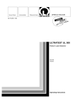
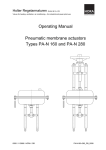
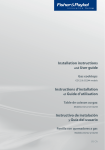
High-pressure Ball Valves HPH HPI HPK HPR HPT HPZ EN English Original Operating Instructions Contents Introduction ............................................................................................................. 3 Availability .................................................................................................................... 3 Types of valve illustrated and described ...................................................................... 3 Design features in the text ............................................................................................ 4 Safety ..................................................................................................................... 4 Proper use .................................................................................................................... 4 Basic safety instructions ............................................................................................... 5 Potential causes of damage and malfunction ............................................................... 7 Qualification of personnel ............................................................................................. 7 Protective clothing ........................................................................................................ 7 Design features of warning instructions in the text ....................................................... 8 Design features of instructions about damage to property ........................................... 8 Description.............................................................................................................. 9 Scope of supply and description of the unit .................................................................. 9 Uses and function....................................................................................................... 13 Storing and transporting the valve .......................................................................... 15 Storing the valve......................................................................................................... 15 Transporting the unit .................................................................................................. 16 Installing and connecting the unit ........................................................................... 17 Preparing for installation ............................................................................................. 17 Mounting the actuator................................................................................................. 18 Connecting the unit .................................................................................................... 21 Operation .............................................................................................................. 23 Correcting faults and disturbances ......................................................................... 24 Eliminating leaks with the emergency sealing system ................................................ 25 After operation ...................................................................................................... 27 Cleaning to remove external dirt................................................................................. 27 Maintenance of the unit .............................................................................................. 27 Repairing the unit and fitting spare parts .................................................................... 32 Taking the unit out of service ................................................................................. 35 Remove hazardous substances ................................................................................. 35 Removing the unit ...................................................................................................... 36 Reusing the unit after storage .................................................................................... 37 Disposal of the unit ..................................................................................................... 37 Technical Data ...................................................................................................... 38 Application limits......................................................................................................... 38 Manufacturer’s declaration .................................................................................... 39 Introduction Availability These Operating Instructions will help you achieve the proper, safe and economical use of the following types of AUDCO Ball Valves: Always keep these Operating Instructions with the plant documentation. Make sure that these Operating Instructions are available to the operator. HPH The Operating Instructions are considered to be a part of the unit. If you sell the unit or pass it on in some other way, these Operating Instructions must be handed over to the new owner. HPI HPK HPR HPT HPZ In the text below, a valve will be referred to as a “unit”. These operating instructions are intended for all persons who commission, operate, maintain, clean or dispose of one or more of these units. The Operating Instructions are intended in particular for customerservice fitters, trained specialist personnel and qualified and authorised operating personnel. Each of these persons must have read and understood the contents of these Operating Instructions Following the instructions contained in these Operating Instructions helps recognise and avoid potential hazards, and increase the reliability and useful life of the units. In addition to the instructions in these Operating Instructions, it is essential to observe and follow the valid, binding accident-prevention regulations, and recognised technical rules for safe and technically correct working that apply in the country and at the location where the valve is installed and used. Types of valve illustrated and described The valves described and illustrated in these Operating Instructions are variants of type HPT DN 200, CL 600 Where other types of valve are shown, this will be expressly stated. The standard units are described in these operating instructions. Please contact the manufacturer for information about valve types not described here. Possible actuators for the unit are not described and illustrated in detail in these Operating Instructions. For more information about an actuator, please see the documentation supplied with it. If you have any queries, please contact the manufacturer. 3 Design features in the text Various elements in these Operating Instructions are furnished with predetermined design features. They make it easy to differentiate between the following elements: Normal text Cross-references Listings Sub-sections in listings Activity steps These tips contain additional information, such as special data about economical use of the unit. Instructions and data in the document supplied with the unit are considered to be an integral part of these Operating Instructions. The operating authority must ensure that only the following activities are carried out: The maintenance operations described in these Operating Instructions (see page 27) Opening and closing the ball valve Pressure testing Air bleeding (optional) Draining (optional) Emergency sealing of the valve stem (optional) Changing valve-stem seals Safety Proper use Emergency sealing of the secondary sealing system (optional) The following types of AUDCO ball valves are for shutting off containers or pipelines containing the following media: Any other activities shall only be carried out by personnel who have been specially trained and authorised by the manufacturer. HPI, HPR, HPT, HPZ: natural gas, mineral oil Any other use of the unit is considered to be improper use. HPH: hot water HPK: brine, caustic potash, lime water or mineral-laden liquids Use of these ball valves with other media is only permissible with the manufacturer’s approval. For other media, consult the manufacturer about the application. The units shall only be used within the permissible pressure and temperature limits, taking chemical and corrosive influences into account. Observing and complying with all data and details in these Operating Instructions, in particular the safety instructions, is implicit in proper use. 4 In particular the use of ball valves to regulate the rate of flow is improper use. If an unsuitable actuator is used to operate the valve, this is also improper use. Using a valve made of materials unsuitable for the medium being handled is also improper use. Basic safety instructions Explosion hazards An explosion hazard arises from using valves that are unsuitable for the environmental condition. Before use in an environment in which there is an explosion hazard, observe the following points: The surface temperature of the valve must not exceed that permissible at the location where it is installed; If the unit is installed so that it is electrically insulated, suitable measures must be adopted to discharge static electricity between pipe connections. If moving parts display extreme resistance to movement, frictional heating may cause an explosion. Ensure that moving parts operate freely. During welding operations to install or remove the unit, there is a risk of explosion or fire being caused by open flames, electric arcs and flying sparks. Observe the valid legal regulations concerning protection against fire and explosions that apply where the unit is installed. The unit and its components shall only be assembled or dismantled by specialist personnel. Danger of serious injury The unit can become hot during operation. Only take the unit into service when insulation or guards prevent contact with hot surfaces. During operation the unit is under pressure and may be hot. Do not carry out work on the unit until the following conditions apply: The pipelines and cavities must be pressure-free; The medium must have been completely emptied from the pipelines and the unit; During any work on the unit, the higher-level plant must be switched off and secured against unauthorised switching back on; The pipelines and the unit must have cooled to about 20 °C (hand warm). For units installed in contaminated areas, there is a danger of severe or lethal injury from hazardous substances on the unit. Do not work on the unit until it has been completely decontaminated. Wear the specified protective clothing during all work in the contaminated area. The unit shall only be used with media that do not attack the material the unit is made from or its seals. Otherwise leaks of hot or poisonous substances may result. The unit and its components shall only be assembled or dismantled by specialist personnel. Specialist personnel must have knowledge and experience in the following sectors: Making connections to pipelines; The selection of lifting gear suitable for the unit, and the safe use of such lifting gear; Working with hazardous media (contaminated, hot, or under pressure). 5 The selection of unsuitable lifting gear, or the incorrect use of lifting gear, can result in the unit or parts of it falling. Allow only specialist personnel to lift the unit or its parts. Make sure that there are never persons under suspended loads. Make sure that lifting gear has adequate load capacity for the load it has to lift, and that such loads are properly attached. Make sure that all valid, local safety and accident-prevention regulations are observed. If the permissible application limits for the unit are exceeded, the unit may be destroyed, or hot or pressurised media released. Make sure that the unit is always operated within the permissible application limits. You will find data on the application limits on the typeplate, and in the Chapter “Technical Data” (observe also the note on Page 38). Failing to use supports with adequate load capacity and sufficiently stable connections to the pipelines can result in damage to the unit. Hot or pressurised media may be released. Allow only specialist personnel to install and connect the unit. If the unit is not adequately supported during installation, the unit may fall or tip over and cause serious injuries (e.g. crushing). Ensure that the unit is adequately supported against tipping and falling during installation. Wear the protective clothing specified at the valve’s location. The unit can be equipped with several different types of actuator, e.g. with an electric or pneumatic actuator. Depending on the energy source for the actuator, there is a danger of severe or lethal injuries from a variety of causes. Before starting any work on the unit, make sure that the actuator 6 is disconnected from the power supply and, where applicable, that there is no pressure in the pneumatic/hydraulic system. Observe and follow all hazard notes in the operating instructions for the actuator. If you have any queries, please contact the actuator manufacturer. There is a danger of severe or lethal crushing by moving parts of the unit. During operation, make sure that no one can be in the vicinity of the moving parts or reach into them. Before any work on the unit, make sure the actuator is switched off and secured against unauthorised switching back on. Danger of less serious injury Cut injuries are possible on the sharp edges of parts inside the unit. During any work on the unit, wear protective gloves. If the unit is inadequately supported during installation, crushing injuries are possible if the unit falls or tips. During installation secure the unit to prevent it falling or tipping. Wear robust safety shoes. Potential causes of damage and malfunction If the unit is installed against the stated direction of flow or in the wrong position, there is a risk of malfunction. The unit or the higher-level plant could be damaged. Install the unit in the pipeline so that the direction of flow corresponds to the flow direction indicated on the valve body. Units made of material that are unsuitable for the flow medium wear faster. This can result in leakage of the medium. Make sure the material is suitable for the flow medium. The unit can be damaged by pressure surges, even when the permissible nominal pressure PN is not exceeded. Make sure the unit is not exposed to pressure surges. Qualification of personnel The operating authority shall only authorise qualified specialist personnel to carry out work on the unit. These persons must, as a result of their training and experience have knowledge of the relevant regulations to ensure safe operation of the unit that apply at the location where it is installed. These include, in particular, the following regulations: Specialist personnel must have knowledge and experience in the following sectors: Valid legal regulations concerning protection against fire and explosions, and work safety that apply where the unit is installed; Working on pressurised equipment; Making connections to pipelines; Working with hazardous media (hot, or under pressure); Lifting and transporting loads; All instructions in these Operating Instructions and other co-valid documents; Making connections to the appropriate power source for the actuator. Protective clothing The protective clothing required depends on the legal requirements where the unit operates and on the media being handled. For more information about suitable protective clothing and protective equipment, see the safety data sheet for the medium being handled. Basic protective clothing has the following components: Hard hat to EN 397 Safety shoes to EN ISO 20345 Legal requirements Robust leather gloves to EN 388 Standards Persons within one metre of the unit while it is in operation must wear ear defenders to EN 352 Accident-prevention regulations Recognised rules for safety and correct working Special instructions issued by the operating authority Depending on the media being handled and valid local regulations, eye protection to EN 166 must also be worn. These persons must be able to recognise, assess and avoid potential hazards. 7 Design features of warning instructions in the text DANGER Instructions with the word DANGER warn of a hazardous situation that will result in death or serious injury. WARNING Instructions with the word WARNING indicate a hazardous situation that could possibly result in death or serious injury. CAUTION Instructions with the word CAUTION indicate a situation that could result in slight or moderately severe injuries. Design features of instructions about damage to property Attention! These instructions warn of a situation that will result in damage to property. 8 Description The unit can be supplied in one of several different states. Scope of supply and description of the unit Unit with actuator mounted Scope of supply The following parts are included in the basic scope of supply: Unit and actuator, possibly with optional actuator connections, are supplied separately Unit without actuator These Operating Instructions When the actuator is part of the scope of supply, the manufacturer will have set it up already. The scope of supply may also include contract-specific, additional documents, for example: At the customer’s request the unit can be supplied packed individually or in any of the following transport packages: Inspection certificates Transport box Material certificates Wire-mesh crate Operating instructions for the actuator Pallet Operating instructions for the gearbox On reception of the delivery, compare the order number on the delivery note with the details on the typeplate. Ball valve For precise details of the scope of supply for your unit, please see the delivery note. As standard, units up to DN 100 are supplied with a hand lever, and units above DN 150 with a gearbox. On request units up to DN 100 can be supplied with a gearbox. Check that all parts are complete and in good condition. Contact the manufacturer without delay if there are deviations or there is anything you are not clear about. We will not accept complaints made later. 9 Description of the unit No. Designation No. Designation 1 Valve stem 6 2 Valve-stem seals Secondary sealing (pressure system) 3 Valve-stem emergency sealing 7 Typeplate 4 Cavity air bleed (from DN 150) 8 Drain valve (from DN 50) 5 Lifting eyes (from DN 200) 9 Body (welded) 10 Ball 10 Optional components The ball valve can be opened and closed either manually with a valve wrench, or by an actuator. The following optional components are available for these units: Drive unit: electric hydraulic pneumatic These underfloor units differ from standard in the following ways: The valve stem is fitted with an extension (11). The sealant lines (15) are extended. The air-bleed line (12) from the airbleed valve (4) is extended (optional). The drain line (13) from the drain valve (8) is extended (optional). Valve wrench The valves (14) for the extended lines are secured to the valve-stem cover at the upper ends on the lines. Air-bleed valve There may be further optional lines. Gearbox for manual operation Drain valve Pressure relief valve (standard equipment on HPH) As an example the illustration shows a type HPZ, DN 500. Parts for underfloor installation The following types of unit can be supplied with emergency sealing: HPH HPK HPT HPZ On these units a leaking valve stem can be sealed without dismantling the actuator. In addition the units are equipped with nipples for applying lubricant under pressure. On these units this allows the user to compensate for wear of the seatingring seals and the valve-stem seals. On units for underfloor installation, the control elements and leads are extended upwards. 11 Typeplate The typeplate bears the following data: Manufacturer Type designation Unit number Serial number Nominal bore Pressure rating Date of manufacture (month/year) Order number Permissible operating pressure at 20 °C or 38 °C Permissible operating pressures at the minimum and maximum temperature limits Test pressure Materials CE-marking (only on units that comply with the Pressure Equipment Directive) Depending on the design code, there may be further data on the typeplate. CE-marking depends on the pressure classification according to the Pressure Equipment Directive. The result is that there will not be CE-marking on all unit types. In accordance with the Pressure Equipment Directive classification, there are the following options: Units to which Pressure Equipment Directive 97/23/EC does not apply bear no CE-marking. Units which fall under Category I of Pressure Equipment Directive 97/23/EC bear only the CE-marking. Units which fall under Category II, III or IV of Pressure Equipment Directive 97/23/EC bear the CE-marking and the number of the Notified Body. Connection types The units can be supplied with the following connection types: Flanges Pipe-welding ends ATEX The unit has no potential ignition sources and is not subject to the “Equipment and protective systems intended for use in potentially explosive atmospheres” Directive, 94/9/EC. These units bear no EX-markings. The markings on the unit and declaration of conformity to Explosion Protection Directive 94/9/EC are not valid for any electric, hydraulic or pneumatic actuator that may be fitted. In this respect observe and follow the information given in the actuator manufacturer’s documentation. 12 Pressure Equipment Directive Uses and function The units that comply with the requirements of Pressure Equipment Directive 97/23/EC can be used for the following media when tested by the manufacturer: Uses Media in Fluid Groups 1 or 2 Units without safety functions can carry a CE-marking from DN 32. A declaration of conformity in accordance with Pressure Equipment Directive 97/23/EG is included with the unit. For pressure and temperature limits, please see the typeplate. Exceptions to this are units that fall under Article 3.3. These units are not allowed to bear a CE-marking. AUDCO ball valves of the types described here are used to shut off containers or pipelines containing liquid or gaseous substances. Function The valve stem (1) turns the ball (10) in the valve body. Depending on the position of the ball, the ball valve is open or closed. In the closed position the ball in conjunction with the various seals prevents the flow of media. Valve-stem seals (2) Ball thrust washer (16) (not on HPT) Seating ring (17) Depending on the type of valve, different sealing systems may be used. On some units the seating ring may incorporate additional seals, depending on the valve type. 13 The seating ring creates a seal between the ball and the valve body. When this seal wears, additional sealing material may be introduced through the resealing system. In addition the units are equipped with nipples for applying lubricant under pressure. On these units this allows the user to compensate for wear of the seatingring seals and the valve-stem seals. Pressure relief For pressure relief, even while the valve is in service, there are optional air-bleed valves and drain valves that can be fitted to the valve body. Pressure relief has the following objectives: To prepare for and carry out leaktesting of the valve. For safely cutting off the flow of media when the unit is used to shut off a pipeline. When the drain valve is open, media that has leaked leaves the valve and cannot enter the shut-off pipeline. For pressure relief before maintenance or repair work on the unit. 14 Storing and transporting the valve Attention! Incorrect storage or transport can damage the valve. Close all openings with the covers supplied or similar covers. Make sure the unit is dry and protected from corrosive atmospheres where it is stored. Contact the manufacturer for advice if you need to store or transport the unit under other conditions. Storing the valve Store the unit only under the following conditions: Do not store it for more than 24 months; Close all openings with the covers supplied or similar covers; The connection surfaces and sealing surfaces must be protected against mechanical damage; The unit and all its components must be protected from blows and shocks. Secure the unit to prevent it falling or tipping. The unit shall only be installed indoors under the following environmental conditions: Relative humidity below 50%, noncondensing; The room air must be clean and not contain salt or other corrosive substance; Temperature 5 - 40 °C. The ball valve must be stored in its “open” position. When storing, make sure these conditions apply at all times. Contact the manufacturer for advice if you need to store the unit for longer or under other conditions. 15 Transporting the unit For transport maintain the same conditions as specified for storage. Before transport fit plugs to the connections. If the plugs originally supplied are not available, use comparable plugs and covers. DANGER Danger of crushing injury if the unit or it components fall or tip. During any work on the unit, wear protective clothing. Whenever lifting or moving the unit or its components to work on them, use suitable lifting gear. Make sure the unit cannot tip over. When lifting the unit, sling it only on the valve body or (above DN 200) from the lifting eyes. Make sure that there are never persons under suspended loads. Protective clothing must comprise at least the following items: Hard hat to EN 397 Safety shoes to EN ISO 20345 Robust leather gloves to EN 388 For more information about suitable safety clothing and protective equipment, see the safety data sheet for the medium being handled. 16 The lifting gear must have adequate load capacity for the unit including its actuator. For more information about the weight of the unit, please see the documentation supplied with it. For more information about the weight of the actuator, please see the manufacturer’s documentation for it. The lighter units can be carried by one person alone or with the aid of an assistant. For heavier units you will need suitable lifting gear to transport them. You can transport the unit over distances of a few metres without packaging. Use the original packing when transporting the unit over greater distances. If the original packing is not available, pack the unit so that it is protected against corrosion and mechanical damage. Transport is also possible at temperatures below 0 °C, as long as the unit has been drained completely and dried. Make sure the unit has been completely drained and flushed. Attach lifting gear with adequate load capacity to the lifting eyes (19). The illustration below shows an example of how to lift the unit with the aid of a beam. The units may also be lifted in other ways. The illustration shows a DN 600 unit. The lifting eyes illustrated are only present on DN 200 or larger units. Attach smaller units to lifting gear with suitable slings. Make sure the included angle between the legs of slings (18) is not more than 60°. Contact the manufacturer if space is so restricted where the valve is located that this type of transport is not possible. Installing and connecting the unit Contact the manufacturer if you need help with the installation, connections or commissioning of the unit. Preparing for installation Take the unit out of its transport packing. Check the unit for transport damage. If you find transport damage, contact the manufacturer. As delivered, the connections may be closed with plugs. Remove the plugs before installation. Keep the plugs and packing materials in a safe place for subsequent use. DANGER When working on pipelines, very serious injuries or death can be caused by burning or poisoning. Make sure there are no hot or hazardous media in the unit or pipelines. Make sure the pipelines at the unit are pressure-free. Make sure the plant is switched off and secured against unauthorised switching back on. Make sure the unit and pipelines have cooled so that they are no more than hand warm. Wear protective clothing suitable for the medium, and when necessary use suitable protective equipment. 17 For more information about suitable protective clothing and protective equipment, see the safety data sheet for the medium being handled. Mounting the actuator Empty the pipelines. Actuators supplied by the manufacturer have a drive coupling that fits the valve. For other actuators the drive coupling must fulfil the requirements of DIN EN ISO 5211. Make sure the pipelines are clean and free from media residues. Switch the plant off and secure it against unauthorised switching back on. Mount either the valve wrench, the gearbox or the actuator on the valve stem of the ball valve. For more information about available and possible actuators, please contact the manufacturer. The actuator must be correctly mounted. When you fit a valve wrench, you must install it so that the position of the ball can be recognised from the position of the wrench. When the ball valve is open, the valve wrench should be parallel to the direction of flow. Mount the valve wrench as described in the installation instructions supplied with it. The connection between the actuator and the valve body should be either direct or by means of a special actuator connection. When an actuator connection is required, this will be mounted on the actuator at delivery. The actuator connection uses the same mountings on the valve body as the actuator. The number of screws required to mount the actuator depends on the valve type. Mounting an actuator on a type HPT, DN 200, CL 600 is described here. The type of mounting on your unit is shown on the drawings supplied. Please contact the manufacturer if you need more information about mounting an actuator. 18 To mount the actuator on the valve body, proceed as follows: Tighten the screws (21) to the correct torque. Make sure that the actuator connection (22) is securely attached to the actuator (20). Place the actuator (20) on the valve stem (1) or the extension (24). Tighten the screws (23 or 25) on the valve body. 19 The torque to tighten the screw or screws depends on their size. The tightening torques in the following table [Nm] should be considered as a guide, because in practice the coefficient of friction may vary substantially. The data here are based on a coefficient of friction of 0.12. If different screw materials are used, ask the manufacturer for the correct tightening torque. Tighten the screw or screws to the torque specified for their size. Stainless steel Thread A4-70 B7 5.6 8.8 10.9 12.9 M8 16 24 11 25 35 42 M10 30 49 23 50 69 83 M12 52 84 40 86 121 145 M14 83 130 64 138 194 232 M16 126 205 100 214 302 362 108 230 324 390 M16x1.5 M18 174 310 138 296 416 500 M20 245 395 195 419 590 708 220 470 660 790 M22 328 525 270 573 806 968 M24 423 675 340 725 1020 1224 M27 617 1000 500 1066 1499 1799 M30 845 1430 677 1444 2031 2437 M20x1.5 20 Steel screws with strength grade NPT G ½“ 115 120 1“ 350 370 Connecting the unit DANGER An incorrectly connected unit can cause an accident that results in very serious injuries or death. Make sure the unit is only connected to the pipeline by suitable specialist personnel. Make sure the direction of flow in the pipeline corresponds to the direction of the arrow on the valve body. The specialist personnel must have knowledge and experience of making connections of the appropriate type to pipelines. Attention! CAUTION Danger of burns from hot surfaces or thermal radiation. Wear protective clothing suitable for the temperatures that occur in the plant. Attention! Seals may be damaged by heat from welding. Make sure the seals are not damaged when welding connections. You can monitor the effects of heat from welding by using temperature-sensing strips. At the positions (26) marked in the illustration below, the temperature during welding must not exceed 180 °C. If the connections are too weak, the valve may be damaged. Make sure the connections are strong enough to withstand the weight of the unit and the forces to be expected in operation. Make sure the pipeline system in the plant is clean. Make sure there are no foreign materials in the valve. Mount the unit so that the valve stem is vertically upwards. On units for which the direction of flow is specified by the customer, the direction of flow is marked on the valve body. Install the valve so that the direction of flow corresponds to the marking. Apply temperature sensing strips at the specified positions. Connect the unit to the pipeline. Observe the temperature sensing strips during welding. If the temperature sensing strips indicate that the area is becoming too hot, cool the seal areas on the valve. 21 After welding remove the temperature sensing strips. When any leakage occurs, proceed as follows: Make sure the unit is securely mounted and that all connections have been correctly executed. When an emergency sealing system is fitted use it as described in the section “Eliminating leaks with the emergency sealing system” from page 25. When the unit is used in air-conditioning, cooling or refrigeration plant, it must be insulated with diffusion-resistant insulation. Insulate the unit with suitable material. The choice of insulation material depends on the temperature of the medium. To receive information about suitable insulation materials, please contact the manufacturer. Connect the actuator correctly to the appropriate energy supply. After installation you must flush the unit and carry out leak testing. Flush the unit and pipeline with clear water or with the medium being handled. Make sure that contaminated water or medium does not enter the plant circulation. To check the function and leaktightness of the unit, open and close it several times while flushing it. Make a visual inspection to check the leak-tightness of the unit. For gaseous media check the unit with an appropriate measuring instrument. Eliminate any leaks found. Run the higher-level plant under operating conditions. You can determine the pressure loss at measuring instruments in the higher-level plant. Check that the ball valve is leak-free under pressure. 22 Otherwise replace the seals, as described in the section “Changing seals” from page 32. Operation CAUTION Danger of burns from hot surfaces or thermal radiation. Wear protective clothing suitable for the temperatures that occur in the plant. You can recognise the position of the ball in several different ways: With a valve wrench: when the ball valve is open, the valve wrench (28) will be parallel to the pipe Without actuator or valve wrench: when the ball valve is open, the key (27) in the valve stem is aligned with the direction of flow. With an actuator: the marking for the “OPEN” position depends on the actuator. For further information, please see the actuator operating instructions. To open the ball valve, turn the valve stem a quarter of a turn anticlockwise, so that the marking is in the “Open” position. To close the ball valve, turn the valve stem a quarter of a turn clockwise, so that the marking is in the “Closed” position. If required, resealing of the valve stem and ball can be carried out while the valve is in operation. For further information about emergency sealing, please see the section “Eliminating leaks with the emergency sealing system” from page 25. During operation do not carry out any other activities on the valve. 23 Correcting faults and disturbances DANGER A damaged unit can cause an accident that results in very serious injuries or death. Replace defective units immediately. Feature Cause Remedy Medium leaks The valve body has been damaged by corrosion or erosion. Replace the unit immediately. The unit has been damaged Replace the unit. by frost. When the plant is switched off, make sure the pipelines and the unit are drained completely. Insufficient flow The valve is not fully open. Open the valve fully. The transport plugs were not Dismantle the unit. Remove the removed. transport plugs. Reassemble the unit. The ball valve does not shut off the pipeline fully. The valve is not completely closed. Close the valve completely. The seating-ring seals are damaged or worn. Have the operating authority seal the unit using the sealant connections. Have the unit repaired by the manufacturer. Replace the unit. Medium leaks The connections are not leak-tight. Seal the connections. A seal in the valve body is defective. Use the emergency sealing system to seal it. There is leakage of medium at the valve stem. The valve stem seal is defec- Apply sealant using the optional tive. emergency sealing system. Replace the valve stem seal. Replace the unit. If you cannot correct the fault by following these instructions, please contact the manufacturer. 24 Eliminating leaks with the emergency sealing system DANGER When working on pipelines, very serious injuries or death can be caused by burns, high pressure, or poisoning. Be sure to avoid touching the unit or pipelines with your hands. Make sure the ball valve is in either the open or closed position. Wear protective clothing suitable for the medium, and when necessary use suitable protective equipment. Observe local safety regulations. For more information about suitable protective clothing and protective equipment, see the safety data sheet for the medium being handled. CAUTION Danger of burns from hot surfaces or thermal radiation. Wear protective clothing suitable for the temperatures that occur in the plant. The protective clothing must protect all body parts from heat and prevent contact between the skin and the medium. This applies in particular to the hands. 25 On the following valve types the valve stem has an emergency sealing system with an injection valve: HPH HPK HPT HPZ This emergency sealing system can be used to seal the valve stem when necessary. To reseal the valve stem you need the following materials and tools: Sealant sticks (AUDCO order number 2473596) Open-ended spanner, 19 A/F Allen key, 5mm Torque wrench and suitable attachment Hold the valve of the emergency sealing system (29) with a spanner to prevent it turning. Remove the socket screw (30) from the injection valve. Push a sealant stick into the injection valve. To inject sealant into the valve body, screw the socket screw into the injection valve. Repeat the injection operation until the unit no longer leaks. Tighten the socket screw (ca. 40 Nm). 26 After operation DANGER For units installed in contaminated areas, there is a danger of severe or lethal injury from hazardous substances on or in the unit. Work on contaminated units shall only be carried out by specialist personnel. Wear the specified protective clothing during all work in the contaminated area. Make sure the unit, including all its cavities, has been fully decontaminated before working on it. During such work follow the instructions for handling the media concerned. Attention! Risk of frost damage to plant that is not in operation. Drain the unit if there is a risk of frost. Cleaning to remove external dirt CAUTION Danger of burns from hot surfaces or thermal radiation. Wear protective clothing suitable for the temperatures that occur in the plant. Remove external dirt from the unit with clean water and a lint-free cloth. To remove stubborn dirt, use a cleaning agent suitable for the deposits and a lint-free cloth. Maintenance of the unit CAUTION Danger of burns from hot surfaces or thermal radiation. Wear protective clothing suitable for the temperatures that occur in the plant. The unit requires little maintenance. For work on the unit you need the following tools: Torque wrench to DIN EN ISO 6789 Hexagon key to EN ISO 4762/ISO 272 Open-ended spanner to EN ISO 4762/ISO 272 Grease gun The properties of the tools, such as the size or measurement range, depend on the type and size of unit. Select tools suitable for the work to be carried out. For work on the actuator, it is necessary to have sufficient working clearance. This depends on the type of unit and the op27 tions fitted. For further details, please see the Technical Data (see also the notes on page 38). When necessary you must carry out the following maintenance work: Checking that the unit operates correctly if it is not regularly opened and closed; Make a visual inspection to check the leak-tightness of the unit; For gaseous media check the unit with an appropriate measuring instrument; Check for leaks by measuring the pressure in the plant during operation; Cleaning the unit. The unit can be cleaned internally by pigging. Lubricating the unit As standard (except for type HPT) the units are filled with Sealant 735 K. Units of the following types must be lubricated once a year with Lubricant/Sealant 735 K (AUDCO Order Number 2473391, Size F) at the secondary seals (grease nipple), unless some other sealant is expressly specified: HPH HPK HPZ Force the lubricant/sealant into the grease nipple with the grease gun supplied (DA 400). Other valve types must not be lubricated. The units have a nipple (6) on the side of the valve body for injecting sealant (from DN 100). In the event of damage to seal- 28 ing surfaces, leakage can be eliminated by injecting sealant. From the injection valve, the sealant passes through a check valve and into the groove in the seating ring. The grease nipple (6) can be replaced without danger during pipeline operation. The sealant can be injected when the valve is either open or closed, and injected against a pressure differential or when the valve is pressurefree: Connect the head of the AUDCO sealant gun to the injection valve. Close the wing screw on the gun. Operate the gun to generate a pressure of about 800 bar. Observe the pressure gauge. If the pressure falls quickly, the sealant is still flowing. Operate the gun again to build up pressure and repeat until the pressure no longer falls, or falls only slowly. The ring grooves are now filled. The injection operation is complete. Undo the wing screw on the gun. Disconnect the head from the nipple. For better distribution of the sealant on the sealing surfaces, the ball can be moved several times in both directions by turning the handwheel. On units that are installed underfloor, the sealant lines are extended up to the operating level. Checking the pressure relief valve On units that are equipped with a pressure relief valve, the pressure relief valve must be checked at the Intervals specified by the manufacturer. Have the pressure relief valve checked by personnel authorised by the manufacturer. The maintenance interval may vary from the recommendation given here to comply with local regulations. When necessary specify a shorter maintenance interval in plant-specific operating instructions. Checking function and leak-tightness Open and close the unit at least once every six months. As you do so check the function and leak-tightness of the unit. When any leakage occurs, proceed as follows: When fitted use the emergency sealing system, as described in the section “Eliminating leaks with the emergency sealing system” from page 25, or the grease nipple, as described in the section “Maintenance of the unit” from page 27. Otherwise replace the seals, as described in the section “Changing seals” from page 32. Draining the unit In this section draining is described and illustrated for a standard unit. On units for underfloor installation, the valves have other locations. An optional drain valve may be fitted to the lower part of the valve body for draining it. Drain the valve body at regular intervals. The interval required depends on conditions where the valve is installed. Contact the manufacturer for precise instructions. On units with the “Double Block and Bleed” function, the drain valve is only used for safe shut-off during repairs and maintenance. For this purpose both the bleed valve and the drain valve must be open. When the ball valve is closed, this ensures that any medium that leaks is drained through the valve. This allows work to be carried out on or in the pipeline downstream of the unit without the danger of contact with the medium at the work site. DANGER The uncontrolled release of medium can result in very serious injuries or death caused by burns, high pressure in the system, or poisoning. Make sure the unit and pipelines connected to it are pressure-free. Make sure that hot or hazardous media are collected in a container that is suitable for those media. Wear protective clothing suitable for the medium, and when necessary use suitable protective equipment. Loosen only the safety screw plug on the unit. For more information about suitable protective clothing and protective equipment, see the safety data sheet for the medium being handled. 29 Hold the drain-screw body (31) with a spanner to prevent it turning when you loosen the drain screw. Loosen the safety screw plug (32). The safety screw plug is designed so that it cannot be opened too far. The drain-screw body (31) is not secured against unintentional removal! Condensate will be blown out. Dispose of the medium in accordance with legal requirements where the valve is installed. Retighten the drain-screw body (31). See the table on Page 20 for the correct tightening torque. 30 Bleeding air from the unit To bleed air from the valve body when handling liquid media, or when pressure testing, an optional bleed valve can be fitted to the upper part of the valve body. In this section bleeding is described and illustrated for a standard unit. Loosen the safety screw plug (33). The safety screw plug is designed so that it cannot be opened too far. The bleed-screw body (34) is not secured against unintentional removal! On units for underfloor installation, the valves have other locations. DANGER The uncontrolled release of medium can result in very serious injuries or death caused by burns, high pressure in the system, or poisoning. Make sure the unit and pipelines connected to it are pressure-free. Make sure that hot or hazardous media are collected in a container that is suitable for those media. Wear protective clothing suitable for the medium, and when necessary use suitable protective equipment. Loosen only the safety screw plug on the unit. For more information about suitable protective clothing and protective equipment, see the safety data sheet for the medium being handled. Hold the bleed-screw body (34) with a spanner to prevent it turning when you loosen the bleed screw. Air is bled from the valve body. Medium may be ejected at the same time. Dispose of the medium in accordance with legal requirements where the valve is installed. Retighten the safety screw plug (33). 31 The torque to tighten the screw or screws depends on their size. Thread Torque [Nm] G/NPT ½” 113 G/NPT1” 150 Tighten the screw or screws to the specified torque. Maintenance of the actuator Maintain the actuator as described in the manufacturer’s operating instructions. Repairing the unit and fitting spare parts You can replace the following parts of the unit if they are worn or damaged: For these units only the seal for the valve stem is available as a spare part. All parts necessary for changing the valvestem seal are supplied in a kit. For more details about how to order a replacement set, please contact the manufacturer. To ensure that your enquiry is dealt with as quickly as possible, please provide the manufacturer with the following information: Unit type Order number Serial number For work on the unit you need the following tools: Torque wrench to DIN EN ISO 6789 Hexagon key to EN ISO 4762/ISO 272 Open-ended spanner to EN ISO 4762/ISO 272 Grease gun The properties of the tools, such as the size or measurement range, depend on the type and size of unit. Select tools suitable for the work to be carried out. For work on the actuator, it is necessary to have sufficient working clearance. This depends on the type of unit, its size and the options fitted. For further details, please see the Technical Data (see also the notes on Page 38). Changing the seals When medium leaks from the valve stem, you must reseal it. 32 On unit types HPH, HPK, HPT and HPZ, there is an emergency sealing system. On these units first seal the valve stem as described in the section “Eliminating leaks with the emergency sealing system” from page 25. When you cannot reseal the valve stem in this way, you must replace the valve stem seal. To do this, proceed as follows: DANGER When working on pipelines, very serious injuries or death can be caused by burns, high pressure in the system, or poisoning. Make sure there are no hot or hazardous media in the unit or pipelines. Make sure the unit and pipelines connected to it are pressure-free. CAUTION Danger of burns from hot surfaces or thermal radiation. Wear protective clothing suitable for the temperatures that occur in the plant. The protective clothing must protect all body parts from heat and prevent contact between the skin and the medium. This applies in particular to the hands. ATTENTION! It is important to remember that the residual pressure in the valvestem-seal zone may be retained over a long period of time. For this reason open the safety screw plug (33) gradually. Make sure the plant is switched off and secured against unauthorised switching back on. Make sure the unit and pipelines have cooled so that they are no more than hand warm. Wear protective clothing suitable for the medium, and when necessary use suitable protective equipment. For more information about suitable protective clothing and protective equipment, see the safety data sheet for the medium being handled. 33 Changing the seal on the HPT Replace the flange (37). Tighten the screws (35). Insert the dowels (36). The torque to tighten the screw or screws depends on their size. See the table on Page 20 for the correct tightening torque. Tighten the screw or screws to the specified torque. To relieve pressure in the cavity, open the air bleed. Remove the dowels (36). Remove the screws (35) around the valve stem, first loosening them progressively. Remove the flange (37). Remove the sleeve (38) with the bearing bush and O-rings. Remove O-rings (39, 43, 44). Remove the sealing ring (40). Remove the pressure ring (42). Remove the graphite ring (41). Make a note of the sequence an ring types. Insert a new graphite ring (41). Insert a new pressure ring (42). Fit new sealing rings (39, 40) to the sleeve (38). Fit new O-rings (43, 44) to the grooves in the sleeve. Place the sleeve (38) with the bearing bush in the flange (37). 34 Changing the seal on the HPZ Taking the unit out of service Remove hazardous substances DANGER For units installed in contaminated areas, there is a danger of severe or lethal injury from hazardous substances on or in the unit. To relieve pressure in the cavity, open the air bleed. Remove the circlip (46). Remove the bearing bush (45). Remove the O-ring (47). Fit a new O-ring (47). Replace the bearing bush (45). Replace the circlip (46). Work on contaminated units shall only be carried out by specialist personnel. Wear the specified protective clothing during all work in the contaminated area. Make sure the unit has been fully decontaminated before working on it. During such work follow the instructions for handling the media concerned. Specialist personnel must have knowledge and experience of the following: legal regulations covering the handling of hazardous substances that apply where the unit is installed special instructions for handling the hazardous substances that occur use of the specified protective clothing. 35 ATTENTION! Environmental damage may be caused by residues of poisonous media. Before disposal make sure the unit has been cleaned and is free of media residues. Dispose of all materials in accordance with the legal requirements that apply where the unit is installed. Remove all residues from the unit. Dispose of all residues in accordance with the legal requirements that apply where the unit is installed. Removing the unit DANGER When working on pipelines, very serious injuries or death can be caused by burns, high pressure in the system, or poisoning. Make sure there are no hot or hazardous media in the unit or pipelines. Make sure there is no residual pressure in the valve cavities. Make sure the unit and pipelines connected to it are pressure-free. Make sure the plant is switched off and secured against unauthorised switching back on. Make sure the unit and pipelines have cooled so that they are no more than hand warm. Wear protective clothing suitable for the medium, and when necessary use suitable protective equipment. For more information about suitable protective clothing and protective equipment, see the safety data sheet for the medium being handled. CAUTION Danger of crushing injury if the unit falls or tips. When dismounting the unit employ suitable measures to secure it against falling. Suitable measures are, for example: For lighter units, having a second person to support it. 36 Supporting heavy units with lifting gear with adequate load capacity. Separating the unit’s connections from the pipeline. Laying the unit on a suitable surface. WARNING Danger of injury from reaching into the unit. Secure the unit during test runs and for large pipe bores. When necessary remove the actuator from the unit. Before removing the actuator, make sure it is pressure-free. When doing this, observe and follow the instructions supplied for the actuator connection and the actuator. When necessary remove the actuator connection from the valve body. Separate the actuator from the actuator connection. Store the actuator and actuator connection on a suitable surface. Store the unit as described in the section “Storing the valve” from page 15. Reusing the unit after storage You can dismount the unit and reuse it at another location if you observe the following conditions: Make sure that all media residues have been removed from the unit, including from its cavities. Ensure that the connections are in flawless condition. If necessary welding connections must be reworked to return them to a flawless condition. Use the unit only for the same application conditions as you would use a new unit. Disposal of the unit ATTENTION! Environmental damage may be caused by residues of poisonous media. Before disposal make sure the unit has been cleaned and is free of media residues. Dispose of all materials in accordance with the legal requirements that apply where the unit is installed. For details of the materials used in the unit, please contact the manufacturer. 37 Technical Data For details of all dimensions and weights, please see the delivery note and the documentation supplied with the unit. Working clearance To remove the actuator from an installed unit, the following working clearance must be kept clear above the actuator: Nominal bore Working clearance S [mm] DN 100–DN 150 500 DN 200–DN 400 750 Over DN 400 1000 Application limits Details of the application limits are given on the unit’s typeplate. 38 Manufacturer’s declaration The declaration of conformity supplied with the unit is a part of the user documentation. It must be kept safely with these Operating Instructions. Any change made to the unit that has not been approved by us renders the declaration of conformity invalid. If you have any questions about the declaration of conformity, please contact the manufacturer at the address below. 39 For our representatives around the world, go to: www.flowserve.com Flowserve Flow Control GmbH Rudolf-Plank-Strasse 2, D-76275 Ettlingen Telephone 0049 (0) 72 43 / 103 - 0 Telefax 0049 (0) 72 43 / 103 - 222 E-mail [email protected] Internet www.flowserve.com To ensure that your enquiry is dealt with as quickly as possible, please provide the manufacturer with the following information: Unit type Order number Serial number You can find the Operating Instruction also in other languages under following link: http://flowserveargus.de/produkte/dokumentationen/produktd atenblaetter Rev. 00, Status 12/2014 40