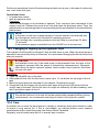
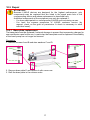
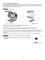
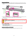
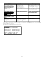
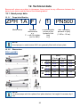
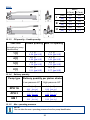
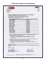
1
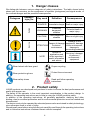
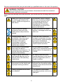
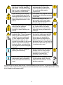
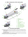
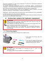
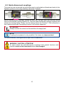
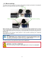
Operating instructions
Hand Pumps ZPH and HM
84120300085 GB
Edition 11.2010
replaces 11.2009
(Translation of the original operating instructions)
2
Contents
Page
1. Danger classes
4
2. Product safety
4
3. Proper use
7
4. Main components of the hand pump
8
5. Functional description
8
6. Connection options for hydraulic equipment
9
6.1 Connecting nipples 9
6.2 Quick-disconnect couplings 10
6.3 Monocouplings 11
7. Commissioning
12
7.1 Locking the pump 12
7.2 Bleeding the pump 12
8. Operation
13
8.1 Operation
13
8.2 Shut-down / Storage 14
9. Transport
14
10. Maintenance and repair
14
10.1 Basic requirements 14
10.2 Maintenance 15
10.3 Changing or topping up the hydraulic fluid 16
10.4 Care 16
10.5 Repair 17
11. Troubleshooting
22
12. Technical data
25
12.1 Hand pump data 25
12.2 Hydraulic fluid recommendation 28
12.3 Operating and storage temperature ranges 28
13. EC Declaration of Conformity
29
14. Notes
30
3
1. Danger classes
We distinguish between various categories of safety instructions. The table shown below
shows you the overview, via the assignment of symbols (pictograms) and signal words, of
the concrete danger and the possible consequences.
Pictogram
Damage /
injury to
Key word
human
DANGER!
Definition
Consequences
Immediate danger Death or major injury
WARNING!
Potentially
dangerous
situation
Potential death or
major injury
CAUTION!
Less dangerous
situation
Minor or slight injury
device
Damage to the
Danger of damage equipment, damage
ATTENTION!
to device /
to the environment,
environment
damage to
surrounding materials
-
NOTE
Advice for
application and
other important /
useful information
and advice
No injury / damage
to persons /
environment /
equipment
Wear helmet with face guard
Proper recycling
Wear protective gloves
Protect the environment
Read and follow operating
instructions
Wear safety shoes
2. Product safety
LUKAS products are developed and produced in order to ensure the best performance and
quality with proper use.
The safety of the operator is the most important consideration in the product design. In
addition, the operating instructions are to help in using the LUKAS products safely.
In addition to the operating instructions, all generally applicable, statutory and other
binding rules for accident prevention and for environmental protection must be heeded and
disseminated.
The device must only be operated by educated persons who are trained in safety technology,
since otherwise there is a risk of injury.
We advise all users before using the device to carefully read through the operating instructions
and to follow the instructions contained therein without exception.
4
We also recommend that you get instructed by a qualified trainer in the use of the product.
WARNING / CAUTION!
The operating instructions for the hoses, the accessories and the connected
devices must also be heeded!
Even if you have already received instruction, you should read the following safety instructions
again.
Make sure that no body parts
or clothing get between the
openly visible moving parts of
the device.
Immediately report changes
that occur (including changes
in operating behaviour) to
the appropriate persons/
departments! If necessary,
immediately shut down and
secure the device!
Wear protective clothing,
protective helm with visor,
safety shoes and protective
gloves.
Check the device for visible
defects or damage before and
after use.
Working under loads is
prohibited if they are raised
exclusively with hydraulic
devices. If this work is
unavoidable, sufficient
mechanical supports are
additionally required.
Check all lines, hoses and
screwed connections for leaks
and externally visible damages
and repair immediately!
Escaping hydraulic fluid can
lead to injuries and fires.
In the event of malfunctions,
shut down the device
immediately and secure it. You
should have the malfunction
repaired immediately.
Do not make any changes
(add-ons or conversions) on the
device without the approval of
LUKAS.
Heed all safety instructions
and hazard warnings on the
device and in the operating
instructions.
All safety instructions and
hazard warnings on the device
are to be kept intact and in a
legible condition.
Make sure that all safety covers
are present on the device and
in proper working condition.
Any work procedure that
detracts from the safety and/or
stability of the device should be
abandoned!
Safety equipment must never
be disabled!
The maximum permissible
operating pressure must not be
changed.
5
Before switching on/engaging
the device or while operating
the device, it must be ensured
that no one is endangered by
the operation of the device.
Observe all intervals that
are prescribed or specified
in the operating instructions
for recurring tests and/or
inspections.
When working in the vicinity
of live components and lines,
take appropriate measures for
preventing current transfers or
high voltage flashovers to the
device.
For repairs only original LUKAS
accessories and spare parts are
to be used.
Prevent electrostatic discharge,
which has the possible
consequence of spark
formation, when handling the
device.
When the hand pumps are set
up, care needs to be taken
that they are not impaired by
extremely strong temperature
changes.
The device is filled with
hydraulic fluid. These hydraulic
fluids can be detrimental to
health if they are swallowed
or their vapours are inhaled.
Direct contact with the skin
should be avoided for the same
reason. Also, when handling
hydraulic fluids, note that they
can negatively affect biological
systems.
When operating and/or storing
the device, make sure that the
function and the safety of the
device are not impaired by
strong external temperature
differences or that the device is
damaged. Keep in mind that the
device can also heat up when it
is continuously used.
Make sure there is adequate
lighting while working.
Before transporting the device,
always check to see that the
accessories are positioned
securely to prevent the
possibility of an accident.
Always keep these operating
instructions easily accessible
at the site where the device is
used.
Make sure you properly dispose
of all removed parts, leftover
hydraulic fluid, leftover oil and
packing materials.
Make sure that you do not
get caught in the hose loops
and trip when working with or
transporting the device.
In addition to the safety instructions of these operating instructions, all generally applicable,
statutory and otherwise binding national and international rules for accident prevention need
to be heeded and disseminated!
6
WAR N IN G / C A U TION / AT T E NT I O N!
The device is specified exclusively for the purpose represented in the operating
instructions (see Chapter "Proper use"). Any use that differs or goes beyond this is
considered improper. The manufacturer/supplier shall not be held liable for damages
resulting from improper use. The risk shall be borne solely by the user.
Proper use also includes heeding the operating instructions and complying with the inspection
and maintenance requirements.
Never work in a fatigued or intoxicated state!
3. Proper use
The LUKAS hand pump is used for the operation of LUKAS devices.
They can be used as an additional or replacement drive source along with the LUKAS
hydraulic unit (e.g. in areas at risk for explosion).
Use with equipment of other manufacturers is possible, but requires technical testing and
approval of LUKAS on a case-by-case basis.
WARNING / CAUTION / ATTENTION!
Always note the product limitations with respect to operating pressure, load limit
values and operating conditions. The operating pressure should not be higher
than the lowest maximum operating pressure of any system components.
The operating pressure should NEVER be set higher than that which is specified
in the "Technical Data" chapter. A higher setting may cause property damage
and/or injuries.
Make sure that the usable capacity of the hand pump (see chapter "Technical
Data") is sufficient for operating the connected cylinders or devices.
The required hydraulic fluid operating quantity can be found in the chapter
"Technical Data" or in the operating instructions of the devices to be operated.
You can obtain accessories and replacement parts for the devices from your authorised
LUKAS dealer!
7
4. Main components of the hand pump
5
9
5
10
1
3
11
12
1
5
13
6
2
7
4
1
5
8
1
1
2
3
4
5
6
7
8
9
10
11
12
13
Drain valve
Bleeding / Filling cap
Pump lever
Tank
Lock
Connecting nipples
Sealing caps
quick-disconnect couplings
(optional)
Connecting block for
monocoupling (optional)
Monocoupling (optional)
Front foot plate (optional)
Rear foot plate (optional)
Base plate (optional)
5. Functional description
All LUKAS hand pumps of this series are two-speed, i.e. they have two operating speeds:
• A high speed in the low pressure range (LP) for fast extension of the cylinder or device
while unloaded
• A low speed in the high pressure range (HP) for controlled extension of the cylinder or
device while loaded
The switch from low pressure (LP) to high pressure (HP) is automatic at the factory setting
for changeover pressure (see chapter "Technical Data").
8
A pressure connection "P" and a return connection "T" with a G1/4“ thread are available for
connecting directly to the pump.
To connect equipment, appropriate connectors (connecting nipples, quick-disconnect
couplings or monocouplings) must be attached. On some of the LUKAS hand pumps offered,
one of these connection options is supplied with the pump and is already fitted.
Obviously, the connection options fitted can be replaced by others. However, you must
contact an authorised LUKAS dealer or contact LUKAS directly.
Additionally, LUKAS hand pumps can be fitted with various accessories (e.g. a baseplate),
to adapt the hand pump to the individual application.
You can obtain the appropriate accessory and any necessary replacement parts for the hand
pumps from your authorised LUKAS dealer.
6. Connection options for hydraulic equipment
ATTENTION!
Make sure to store all plugs, screw plugs and/or dust caps in a way that
prevents them from getting dirty or lost.
After completion of the work, seal off all lines using screw plugs and/or dust
caps to prevent contamination of the hand pump.
When connecting lines to the hand pump, we recommend positioning it
vertically so that the ports point upward. This reduces the danger of hydraulic
fluid escaping.
6.1 Connecting nipples
The hose lines are connected via fittings to the hydraulic pump.
1. First remove the closure caps from
the fittings.
1.
2.
2. Then, you can connect the hose lines
to the fittings and tighten them with a
tightening torque of MA = 40 Nm.
ATTENTION!
The return hose must always be connected at the "T" port of the
connection block.
The supply hose line must instead be connected at the "P" port.
9
6.2 Quick-disconnect couplings
The hose lines are connected via quick-disconnect coupling halves (female and male) to the
hydraulic pump in such a way that they cannot be reversed.
X
Y
Before connecting the couplings, remove the dust cap, then pull back and hold the locking
sleeve of the female coupling (Position X). Push the male and female couplings together and
release the locking sleeve. Finally, turn the locking sleeve into Position Y. The connection is
then made and secured. Decoupling is done in the reverse sequence.
ATTENTION!
Always connect the return line first and then the supply line!
NOTE:
Coupling the equipment is only possible if the hoses are depressurised.
For dust protection, the supplied dust caps must be reattached.
WARNING / CAUTION / ATTENTION!
To some extent the quick-disconnect couplings have special functions and
therefore must not be unscrewed and/or interchanged!
10
6.3 Monocouplings
The hose lines are connected via monocoupling halves (female and male) to the hydraulic
pump in such a way that they cannot be reversed.
Dust caps
Male coupling
Female coupling
Before coupling, remove dust caps, then connect male and female couplings and turn locking
sleeve of the female coupling in direction "1" until the locking sleeve latches. The connection
is then made and secured. The decoupling is accomplished by turning the locking sleeve in
direction "0".
The coupling of the devices under pressure is also possible, assuming the connected
equipment is not turned on.
NOTE:
We recommend, when ambient temperatures are low and extension hoses
are used, connecting the coupling halves in a depressurised state because
decoupling may otherwise require a very large exertion of force.
For dust protection, the supplied dust caps must be reattached.
WARNING / CAUTION / ATTENTION!
The monocouplings must not be unscrewed and/or the hose lines reversed!
11
7. Commissioning
NOTE:
With the LUKAS hand pump, a little idle stroke may occur when the unit is first
used in the high pressure range.
However, this idle stroke independently stops after a device is operated
2-3 times.
ATTENTION!
The hand pump should be as close to horizontal as possible, because otherwise
the usable amount changes!
The oil fill plug must always be unscrewed one turn before starting operation of
the hand pump! This enables the aeration and bleeding of the hydraulic tank.
After the work is completed but before transport, the oil fill plug should be
retightened!
7.1 Locking the pump
Unlock:
Lock:
ATTENTION!
Always push the locking lever fully to the end position, both when locking and
when unlocking!
When locking the hand pump, the pump lever must always be in the home
position (end position against the pump body)!
7.2 Bleeding the pump
1. Open the discharge valve.
2. Open the oil fill screw plug on the tank container and check the oil fill level. The oil fill
level should come up to approximately 1-2 cm below the top edge of the oil reservoir.
3. In this state, work the pump handle several times.
Hand wheel
12
NOTE:
To bleed connected equipment, make sure that the highest point of the connected
devices are below the level of the pump.
Before operating the pump, you should also open the oil fill screw plug. Only in this
way can any trapped air escape the hydraulic system when the pump is operated.
You should operate the connected equipment several times without load.
When you do this, also follow the separate operating instructions of the connected
devices.
8. Operation
WARNING / CAUTION!
Under certain circumstances, the pump handle can "kick back". Make sure that
your body remains to the side of the pump.
ATTENTION!
Never attach an extension to the pump handle that does not belong to the
device. These extensions usually cause the pump to become unstable during
operation.
NOTE:
In order to limit the required force in high pressure operation, we recommended
using short strokes with the pump handle. The greatest pumping effect is produced
in the last 5 degrees of the stroke.
Should you use a female quick-disconnect-coupling as the port, quick stop may be
triggered if the discharge valve is opened too quickly (turning counter-clockwise),
i.e. the check valve incorporated in the male quick-disconnect coupling blocks
the return flow of oil while the connection between pump and female quickdisconnect coupling is depressurised. This is provided as a safety function in case
the connection between the female quick-disconnect-coupling and pump starts
to leak and the pressure drops abruptly. In this case, the "quick stop" prevents,
for example, an abrupt drop in the load when an hydraulic cylinder is operated.
In order to release the quick stop again, more pressure must first be supplied to
the device. Then, the pressure can be decreased again by slowly opening the
discharge valve.
8.1 Operation
Procedure:
1. Close discharge valve on the hand pump completely (rotate clockwise).
2. Connect the return line of the device at the return port "T" and then the high pressure line
at the pressure port "P".
3. Move the locking lever into the operating position (unlock).
4. Supply the device with hydraulic fluid or pressurise by operating the pump lever (up and
down movements).
5. To reduce the pressure of the device, slowly open the discharge valve of the hand pump
(turn counter-clockwise). In this way, you can meter the pressure reduction precisely.
13
8.2 Shut-down / Storage
To shut down or store the pump, seal all hydraulic connections with the associated screw
plugs or dust caps.
After sealing the hydraulic ports, open the drain screw (not up to the stop!) to depressurise
the pump.
Then carefully clean the external dirt off of the hand pump.
In addition, with a longer storage time, the outside of the device should be cleaned and all
visible mechanical moving parts need to be oiled.
ATTENTION!
After completion of the work but before transport, check to make sure the oil fill
screw plug is screwed in tightly!
Make sure the pump is not stored in a damp environment.
9. Transport
The pump lever is used as a carrying handle! Special pumps may be the exception in this
case. These pumps are custom-assembled for each customer; therefore, there may be a
different transport device or none! In these cases, please refer to your authorised dealers or
LUKAS directly. The lever must be locked for transport, as described in the chapter "Locking
the pump".
10.Maintenance and repair
10.1 Basic requirements
Service work may only be performed by the device manufacturer, or by personnel trained by
the device manufacturer, and authorised LUKAS dealers.
All components must be replaced with original LUKAS spare parts, which are listed in the
spare parts list, because in this context even required special tools, assembly instructions,
safety aspects and/or checks absolutely must be taken into consideration.
During the assembly work, pay particular attention to the cleanliness of all components
because dirt can damage the equipment!
WARNING / CAUTION / ATTENTION!
To perform maintenance and repairs, personal safety equipment appropriate for
the work is an absolute requirement (incl. shields).
Assembly and repair work on the pump may only be performed if the entire
hydraulic system is depressurised!
Couplings should not be repaired; they should be replaced with original LUKAS
parts!
NOTE:
Always send the warranty card back to LUKAS Hydraulik GmbH.
You should always contact LUKAS or an authorised dealer before using couplings
from a different company.
Do not perform any repairs without the corresponding LUKAS spare parts list,
because necessary tightening torques for screw connections and/or in some
cases also important additional information are listed there.
14
ATTENTION!
Clean the device before checking for dirt!
Do not use any aggressive agents for cleaning; it could cause damage to the
equipment.
Because LUKAS devices are designed for the highest performance, only
components may be replaced that are listed in the spare parts lists of the
corresponding device.
Additional components of the equipment may only be replaced if:
- You have participated in a corresponding LUKAS service training course.
- You have the express permission of LUKAS customer service (by
request, check on the grant of permission. A check is necessary in each
individual case).
The equipment is subject to very high mechanical stresses. Therefore, a visual inspection
needs to be made after each use, at least once per month (if continually used, once per
week).
In this way, early signs of wear are recognisable so that damage to the device can be avoided
by prompt replacement of these worn parts. Also check regularly to make sure that all
attachment screws are tightened (observe any applicable tightening torque specifications).
At least once a year (if continually used, once every half year) or if there is a doubt about
the safety or reliability, a functional check should also be performed (for this purpose, also
heed the corresponding applicable national and international specifications related to the
maintenance intervals of the devices).
10.2 Maintenance
Before performing maintenance work, clean the hand pump thoroughly.
After performing the maintenance work, you should carefully coat all metallic parts with oil
to prevent any corrosion.
Checks (Maintenance measures):
Perform a visual inspection of the hand pump at least once per month; in the case of
continuous use, once a week.
Visual inspection
Hand pump
• are all hydraulic connections still tightened,
• generally sealed, no leaks present (oil "sweat" has no effect on the operation),
• is damage to pump housings, valve blocks or attachment parts recognisable, especially
on the moving parts such as the piston rods,
• are all fluid levels within the prescribed tolerances,
• are all non-moving parts firmly attached,
• is there no corrosion,
• free movement of the pump lever, the locking mechanism and the hand wheels
(check in the depressurised state),
• the couplings are easy to couple (if attached),
• are dust caps in place,
• are identification plate, all control decals, instruction decals, labels and warnings present
and legible.
15
Perform an operational check of the hand pump at least once a year; in the case of continuous
use, once every half year.
Operational check
• no suspicious noises,
• tests at maximum load.
Execution:
Place the hand pump on a solid base to operate. Then, connect a test manometer to the
supply hose line. Release the pump lever lock and close the discharge valve. Then, the
pressurisation to operating pressure corresponding to the specification on the identification
plate occurs.
NOTE:
In this test, an idle time of approximately 2 minutes needs to be observed and
the hand pump needs to be reloaded to operating pressure.
The resulting max. operating pressure must not drop by more than 5% after
10 seconds.
A test pressure gauge is available from the LUKAS line of accessories.
10.3 Changing or topping up the hydraulic fluid
The hydraulic fluid should be changed if dirty at least once a year. When the hand pump is
operated in an especially dusty environment, we recommend changing the fluid at least once
every six months.
ATTENTION!
Add hydraulic fluid only if the hand pump is disconnected from the lines or the
equipment operated with the pump is hydraulically depressurised. Otherwise,
after filling the entire hydraulic system could contain more hydraulic fluid than
the tank can hold.
Procedure:
1. Open the bleed/fill cap on the tank.
2. Add hydraulic fluid until the fluid level comes up to 1-2 cm below the top edge of the oil
tank.
3. Bleed the hand pump as described in the chapter "bleeding the pump".
4. Check the fluid level again and close the tank again at the correct fluid level with the
vent/fill cap on the tank. Should the tank no longer be sufficiently full after bleeding, start
the fill procedure again at item 2.
NOTE:
Should the fluid level in the tank still not be reached after repeated refilling (during
maintenance), we recommend searching for leaks in the hydraulic system.
10.4 Care
If possible, do not store the hand pump in a damp or extremely dusty environment in order
to ensure a long service life. If this is unavoidable, you should perform more frequent
maintenance and/or shield the pump from these effects if possible.
Regularly coat all metal parts with oil to prevent any corrosion.
16
10.5 Repair
ATTENTION!
Because LUKAS devices are designed for the highest performance, only
components may be replaced that are listed in the spare parts lists of the
corresponding device and whose replacement is described here.
Additional components of the equipment may only be replaced if:
- You have participated in a corresponding LUKAS service training course.
- You have the express permission of LUKAS customer service (by
request, check on the grant of permission. A check is necessary in each
individual case!).
10.5.1 Base plate replacement
The base plate must be replaced if external damage is present that represents a danger for
user and device upon further use. In particular, the base plate must be replaced if the stability
of the hand pump can no longer be ensured.
Procedure:
1. Remove screws A and B and also washers C and D.
A
D
B
C
E
2. Remove base plate E and replace it with a new one.
3. Refit the base plate in the reverse order.
17
10.5.2 Foot plate replacement
The foot plates must be replaced if external damage is present that represents a danger for
user and device upon further use. In particular, the foot plates must be replaced if the stability
of the hand pump can no longer be ensured.
Procedure:
1. Remove screws A or B.
Front foot plate:
Rear foot plate:
C
D
A
B
2. Remove foot plate C or D and replace it with a new one.
3. Refit the foot plates in the reverse order.
10.5.3 Removing tank for cleaning, replacing the tank or the seals
The tank should be cleaned at least once per year in order to remove the accumulated dirt.
The tank must be replaced if there is any external damage that impairs the safety of
the device.
The tank seals must be replaced if there are any leaks at the junction points of the tank.
Procedure:
1. Remove base plate as described in the chapter "Replacing
base plate".
2. Empty tank by removing the screw plug (item D) and emptying
the tank.
18
D
Removing the ZPH1/HM1 1l tank:
3. Remove the nut (item E) and sealing ring situated under it (item F).
4. Remove the tank, the seals (item G), the cover (item R) and the filter (item H). On the
rescue hand pumps, the intake pipe (item J), the threaded rod (item K), the washer (item
L), the O-ring (item M), the serrated washers (items N, O and P) and the bracket (item Q)
must also be removed.
Pump head
J
K
Tank
H P M
L
O
G
N
Q
N
G
R
F
E
6. The assembly is done in reverse order. Replace all damaged parts with new ones. The
tightening torque of the nuts is 40 Nm.
Removing the ZPH1/HM1 5l and 12l tanks:
3. Remove the screws (item R) and the lock washers under them (item S).
4. Remove the tank, the O-rings (items T and U), the serrated washer (item V) and the filter
(item W).
W V
R
T
U
S
6. The assembly is done in reverse order. Replace all damaged parts with new ones. The
tightening torque for the screws is 10 Nm.
19
Removing the ZPH3 tank:
3. Remove the screws (items A and B) and the lock washers under them (items C and D).
4. Remove the tank, the O-rings (items E and F), the serrated washer (item G) and the filter
(item H).
A
C
Tank
H G E F
D
B
5. The assembly is done in reverse order. Replace all damaged parts with new ones. The
tightening torque for screws "A" is 24 Nm, and for screws "B" is 10 Nm.
10.5.4 Couplings
WARNING / CAUTION / ATTENTION!
Couplings should not be repaired; they should be replaced with original LUKAS
parts!
10.5.4.1 Monocouplings
The monocouplings must be replaced if:
- exterior damage is present,
- the lock does not function,
- in the coupled and/or decoupled state, hydraulic fluid continuously escapes.
Procedure for installation in the valve block:
1. Unscrew coupling from connection plate.
2. Screw new coupling into the connection plate with a torque of MA = 40 Nm.
20
10.5.4.2 Quick-disconnect couplings
The quick-disconnect-couplings should be replaced if:
- exterior damage is present,
- the lock does not function,
- in the coupled and/or decoupled state, hydraulic fluid continuously escapes.
Procedure:
1. Unscrew and remove coupling.
2. Screw in new screw-on male coupling and tighten with a torque of MA = 35 Nm.
ATTENTION!
The return port must always be equipped with a female quick-disconnectcoupling.
The supply port should instead be equipped with a male quick-disconnectcoupling.
10.5.5 Decals
All damaged and/or illegible decals (safety instructions, identification plate, etc.)
must be replaced.
Procedure:
1. Remove damaged and/or illegible decals.
2. Clean surfaces with acetone or industrial alcohol.
3. Adhere new decals.
Make sure to adhere the decals in the correct positions. If this is no longer known, you should
consult your authorised LUKAS dealer or contact LUKAS directly.
21
11.Troubleshooting
Problem
Connected device
does not move, moves
only slowly or moves
intermittently.
Cause
Remedy
Fluid level in the hydraulic
tank too low
Add hydraulic fluid up to
max. fill level.
Discharge valve open
Hose line not properly
connected or damaged
Close discharge valve.
Check connection of the
hose line and reconnect it
if necessary.
Load on the device
Use a different device.
too high
Air in the hydraulic system Bleed system as described
in the chapter “Bleeding
the pump”.
Defect on the device
Heed the specifications
of the separate operating
instructions of the
device.
Connected device moves, Hose line not properly
Check connection of the
but does not hold pressure connected or damaged
hose line and reconnect it
or does not render the
if necessary.
specified performance.
Leaking seal
Locate the leak and have
the hand pump serviced by
an authorised dealer, by
personnel specially trained
by LUKAS or by LUKAS
directly.
Internal leakage of the
Have the hand pump
pump
serviced by an authorised
dealer, by personnel
specially trained by LUKAS
or by LUKAS directly.
Discharge valve closed
Open discharge valve.
Device does not move
back into the starting
Fluid level in the hydraulic Reduce hydraulic fluid
position, moves
tank too high
down to max. fill level.
incompletely back toward
Loose
hydraulic
coupling
Check all couplings and
the starting position or
retighten them.
moves more slowly into
the starting position than
Enclosed air in the system Bleed pump as described
normal.
in the chapter “Bleeding
the pump”.
Line length too long
Use shorter lines.
Use hydraulic fluid with
a different, more suitable
viscosity.
Defect on the device
Heed the specifications
of the separate operating
instructions of the
device.
22
Problem
Cause
Remedy
Connected device not
reaching its limit position
Fluid level in the hydraulic
tank too low
Connected device does
not achieve its powerrelated performance data
Attention: move the
device back into the
base position before
adding fluid!
Usable hydraulic fluid
Use a different device with
quantity of the pump is
a usable quantity below
insufficient
the maximum usable
quantity of the pump.
Max. permissible operating Replace pressure
pressure of the pump is
control valve or have
not reached
it recalibrated by an
authorised dealer or
directly by LUKAS.
Due to return flow of the
Reduce hydraulic fluid
hydraulic fluid from the
down to max. fill level.
device, the maximum fill
quantity of the tank is
exceeded
Seals defective
Replace seal.
Fluid leaks on the
hydraulic fluid tank
(especially at the refill tap)
Add hydraulic fluid up to
max. fill level.
Hydraulic fluid with milky
cloudiness
Water or condensation
water in the system
Perform hydraulic fluid
change immediately.
In the case of a
monocoupling system:
Hose lines cannot be
coupled
They are under excessive
pressure (e.g. due to
excessive ambient
temperature)
Coupling defective
Open discharge valve and
bleed device.
In the case of a
monocoupling system:
Hose lines frequently
cannot be coupled
Hydraulic fluid of the
application situation not
adapted
Coupling defective
In the case of a quickSystem is under pressure
disconnect coupling
system: Hose lines cannot Coupling defective
be coupled
In the case of a
monocoupling system:
Leakage at the couplings
Coupling defective
23
Coupling should be
replaced immediately.
Hydraulic fluid needs
to be changed (see the
chapter “Hydraulic fluid
recommendation” for more
information).
Coupling should be
replaced immediately.
Open discharge valve and
bleed device.
Coupling should be
replaced immediately.
Coupling should be
replaced immediately.
Problem
Cause
Remedy
In the case of a quickdisconnect coupling
system: Leakage on the
male coupling
Safety valve has
responded (in the
decoupled state)
Male coupling defective
After depressurisation, no
further leakage occurs.
In the case of a quickdisconnect coupling
system: Leakage at the
female coupling
Hydraulic fluid escaping
from the hoses or at the
joints
Damage on the surface of
the hydraulic hoses
Female coupling defective
Female coupling should be
replaced immediately.
Male coupling should be
replaced immediately.
Leakage, possible damage Replace hoses.
Mechanical damage or
contact with aggressive
media
Replace hoses.
If the defects cannot be remedied, notify an authorised LUKAS dealer or contact LUKAS
Customer Service directly!
The address of LUKAS customer service is:
LUKAS Hydraulik GmbH
Weinstraße 39,
Postfach 2560,
D-91058 Erlangen
D-91013 Erlangen
Phone: (+49) 09131 / 698 - 348
Fax.: (+49) 09131 / 698 - 353
24
12.Technical data
Because all values are subject to tolerances, there cannot be any differences between the
data of your device and the data of the following tables!
12.1 Hand pump data
12.1.1 Pump identification
ZPH 1A F / 1
Model series
Optional
attachments
e.g.
F= with foot plates
(not for HM1)
PN500
max. operating
pressure in [bar]
(1 MPa = 10 bar)
rounded usable
volume of the
hydraulic fluid
tank
in [l]
NOTE:
Hand pumps in model series HM1 are generally fitted with a base plate.
12.1.2 Dimensions
ZPH1 and HM1:
ZPH 1
HM 1
(1l Tank) (5l Tank)
L
B
H
[mm]
621
628
623
[in.]
24.4
24.7
24.5
[mm]
112
164
200
[in.]
4.4
6.5
7.9
[mm]
195
195
215
[in.]
7.7
7.7
8.5
NOTE:
On hand pumps with the optional foot plate attached, the height H increases by 6
mm.
25
ZPH3:
ZPH 3
(4l Tank) (8l Tank)
L
B
H
[mm]
762
762
[in.]
30
30
[mm]
150
230
[in.]
5.9
9.1
[mm]
231
231
[in.]
9.1
9.1
12.1.3 Fill quantity - Usable quantity
Tank size
Usable quantity Max. fill quantity
(according to pump
identification)
1 [l]
4 [l]
5 [l]
8 [l]
1,1
0.29
4,0
1.06
4,5
1.19
8,0
[l]
[gal.-US]
[l]
[gal.-US]
[l]
[gal.-US]
[l]
1,3
0.34
5,3
1.40
5,0
1.32
10,5
2.11 [gal.-US]
[l]
[gal.-US]
[l]
[gal.-US]
[l]
[gal.-US]
[l]
2.77 [gal.-US]
12.1.4 Delivery quantity
Pump type
Delivery quantity per piston stroke
Low pressure LP
ZPH 1A
ZPH 3
HM 1
10
0.61
10,8
0.66
10
0.61
[cm³]
[cu. in.]
[cm³]
[cu. in.]
[cm³]
[cu. in.]
High pressure HP
1,6
0.10
4,2
0.26
1,6
0.10
[cm³]
[cu. in.]
[cm³]
[cu. in.]
[cm³]
[cu. in.]
12.1.5 Max. operating pressure
NOTE:
You can take the max. operating pressure from the pump identification.
26
12.1.6 Change-over pressure LP - HP
Pump type
Change-over pressure
10
1,450
18
2,611
10
1,450
ZPH 1A
ZPH 3
HM 1
[MPa]*
[psi.]
[MPa]*
[psi.]
[MPa]*
[psi.]
*) 1 [MPa] = 10 [bar]
12.1.7 Weight
Total
weight
Pump type
ZPH 1A
ZPH 3
HM 1
=
+
Weight
(Pump head)
Weight
(Tank)
+ (Accessories)
Weight
Weight
Tank size
Weight
(Pump head)
(according to pump
identification)
(Tank)
4,6
10.1
3,7
8.2
4,7
10.4
[kg]
[lbs.]
[kg]
[lbs.]
[kg]
[lbs.]
1 [l]
4 [l]
5 [l]
8 [l]
Accessories
Weight
1,28
2.83
0,18
0.40
0,07
0.15
0,04
0.09
0,29
0.64
0,12
0.26
0,73
1.61
Base plate
Foot plate (front)
Foot plate (rear)
Connecting nipples
Quick-disconnect
coupling, female
Quick-disconnect
coupling, male
Monocoupling
27
[kg]
[lbs.]
[kg]
[lbs.]
[kg]
[lbs.]
[kg]
[lbs.]
[kg]
[lbs.]
[kg]
[lbs.]
[kg]
[lbs.]
1,4
3.1
4,4
9.7
4,0
8.8
6,2
13.7
[kg]
[lbs.]
[kg]
[lbs.]
[kg]
[lbs.]
[kg]
[lbs.]
12.2 Hydraulic fluid recommendation
Mineral oil DIN ISO 6743-4 for LUKAS hydraulic equipment and others
Oil temperature range
-20 .... +55°C
Oil code
HM 10
Viscosity rating
VG 10
Remarks
A
Oil code
HM 10
Viscosity rating
VG 10
Remarks
A
Oil temperature range
-4.0 .... +131°F
recommended viscosity range: 10...200 mm²/s
Supplied with HM 10 DIN ISO 6743-4.
(10…200 cSt.)
ATTENTION!
Before using hydraulic fluids that do not correspond to the aforementioned
specifications and / or are not purchased from LUKAS, you must contact
LUKAS!
12.3 Operating and storage temperature ranges
Operating temperature
[°C] / [°F]
-20 … +55
-4 …
+131
Ambient temperature
(device in operation)
[°C] / [°F]
-25 … +45
-13 …
+113
Storage temperature
(device not in operation)
[°C] / [°F]
-30 … +60
-22 …
+140
28
13.EC Declaration of Conformity
29
14.Notes
30
31
Please properly dispose of all packing
materials and removed parts.
LUKAS Hydraulik GmbH
Phone: (+49) 0 91 31 / 698 - 0
Fax.: (+49) 0 91 31 / 698 - 394
e-mail: [email protected]
Made in GERMANY
ZPH_HM_BA_GB_84120300085_1110.indd
© Copyright 2010 LUKAS Hydraulik GmbH
Subject to revision
Weinstraße 39, D-91058 Erlangen
Postfach 2560, D-91013 Erlangen